Journal of Korea Multimedia Society Vol. 20, No. 4, April 2017(pp. 671-685) https://doi.org/10.9717/kmms.2017.20.4.671
Finger Detection Algor ithm For Computer Mouse Contr ol Gendusa Tulonge Rodrigue†, Eung-Joo Lee††
ABSTRACT
We propose a finger detection algorithm for computer mouse control to control the most commonly actions of a computer mouse(left, right and double click, scroll up and down then we add open and close, minimize and maximize a window, control the mouse.) We use a built-in web camera to control the mouse tasks. We detected, segment, then recognize the hand in our previous papers [1, 2]. The user will be able to interact with the computer with the number of fingers detected. Key words: Finger Detection, Mouse Control, HCI, HMM, Neural Network 1. INTRODUCTION
Recently in HCI, the detection of finger and finger types has received growing attention in applications like sign language, vision based finger guessing games and in applications related to real-time systems and virtual reality and recognizing pointing gestures in the context of human-robot interaction[3]. A new concept of interaction has, thus, emerged: human-computer interaction (HCI). Although the computers themselves have advanced tremendously, the common HCI still relies on simple mechanical devices keyboards, mice and joysticks that tremendously reduce the effectiveness and naturalness of such interaction. This limitation has become even more evident with the emergence of a new concept surrounding this interaction [4]. Several finger detection, Hand gesture recognition techniques already exist and most of them are based on Hidden Markov Models (HMM), ※ Corresponding Author : Eung-Joo Lee, Address: (48520)Sinseon-ro 428, Nam-gu, Busan, Korea, TEL : +82-51-629-1143, FAX : +82-51-629-1169, E-mail :
[email protected] Receipt date : Dec. 12, 2016, Revision date : Mar. 21, 2017 Approval date : Mar. 24, 2017
Fuzzy Logic, Neural Networks, etc. Human Computer Interaction (HCI) is an interesting and involved area of research. Many researches and engineers involved in this field research and develop new and simpler ways to interact with the computers. These new ways are not restricted for interaction with computers. These methods are not robust enough for real-time implementation. To overcome this, we develop a robust finger detection algorithm for a computer mouse which depends purely on the simple segmentation and techniques [11]. Our focus is on hand gesture recognition in natural way without using any marker of sensor based gloves [12]. Our method does use neither Hidden Markov Models (HMM) nor Fuzzy Logic. After segmenting the hand and figure out the number of finger have been detected by our convex hull algorithm, we are going to save a new session that will allow the system to do not detect other hand in an environment that has so many hands. Department of Information and Communication Engineering, TongMyong University (E-mail :
[email protected]) ††Department of Information and Communication Engineering, TongMyong University ※ This research was supported by the Busan Metropolitan City, Korea, under the 2017 BB21 program grants. ††
672
JOURNAL OF KOREA MULTIMEDIA SOCIETY, VOL. 20, NO. 4, APRIL 2017
Once a session is created, no any other session can be created unless the previous session has been destroyed. The user will be able to interact with the computer by executing several actions such as: Left click and Right click, Scroll Up and Down, the Double click event, Minimize an active window or Maximize it and Open a recently closed window or file and Close an opened window or file This simulation is being carried on an All-InOne Samsung ATIV with 2.50GHz of processor, 16 Gigabytes of Read Access Memory (RAM) on a Windows 10 Operating system, 27 inches of screen resolution with a built-in webcam. 2. RELATED WORK
A lot of works have been done in this area for dynamic hand gesture recognition using fingertip detection. Most of them are not robust enough for real-time implementation and all of them use ambiguous methods for making a click event of a mouse [5]. In earlier days hand gesture detection was done using mechanical devices to obtain information of the hand gesture. One of the most widely used and accepted examples for hand gestures recognition is data glove. Evolution of computer hardware improved a lot of in present scenario this also effects the performance of computing. Enhancements of gesture recognition has replaced the role of data gloves to non-wearable devices due to its naturalness without using any device this is quite user friendly in human computer interaction. One of the major drawbacks of data glove is that it is cumbersome with the limitation of hand movement [13]. This paper is being inspired by the work of Asanterabi Malima et al. [6]. They developed a finger counting system to control behaviors of a robot. We use their algorithm to estimate the radius of the hand region and other algorithms in our image segmentation part to improve our results.
The segmentation is the most important part in this project. Our system uses a color calibration method to segment the hand region and a convex hull algorithm to find fingertip positions [5]. 3. PROPOSED METHODOLOGY
We propose in this paper a real time non-invasive finger detection algorithm. In this section we explain our method divided in eight main steps. The first step, hand segmentation where the image region that contains the hand has to be located. In order to make this process possible, we use shapes, but they can be greatly interval that hand moves naturally [7]. So, select skin-color to get characteristic of hand. The skin-color is a distinctive cue of hands and it is invariant to scale and rotation. In the next step we use the estimated hand state to extract several hand features to define a deterministic process of finger recognition. To detect fingers or fingertips, hand regions must be detected first [14-20]. Skin color [14-16], edge [17], and temperature [18] have been used for the detection. Hand edges can be easily extracted only from uniform background images and methods based on skin color may fail under complicated or dynamic lighting. To solve these problems, gradient, 3D, and motion information was used on the extracted skin regions in [19-23]. The use of temperature is not very practical, owing to the expense of infrared cameras [18], dominant points [15], and polar coordinates have been used to detect fingers or fingertips from the extracted hand region; however, these methods encounter difficulty due to noise, scale, and hand direction. Methods that detect hand regions from gray scale images have been proposed [24, 25]; only uniform backgrounds were considered. Motion features may be used to track fingers [26, 27], but precise finger motions may not easily be tracked by region motion. Color cue is the main information that is being exploited to detect hand and thus fingertip. The
Finger Detection Algorithm For Computer Mouse Control
673
(1) Where (x’, y’) is the camera position, (cx, cy) is the current screen resolution, and (x, y) is the corresponding screen position of camera position. 3.2 Color Segmentation
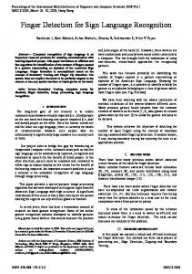
Fig. 1. An overview of our finger detection algorithm for computer mouse. Input image converted to binary image to separate the hand background. Center of hand and computed, calculated radius of hand found. Fingertip points using Convex Hull algorithm. Mouse controlled using hand gesture.
method to detect is based in a color model of the skin-color pixel. After the hand is segmented from the background, counter is extracted. The counter vector contains the series of edges of hand. Then the processing of counter vector gives the location of the fingertip.
Segmentation is the process of assigning each pixel in the source image to two or more classes. If there are more than two classes then the usual result is several binary images. The simplest form of segmentation is probably Otsu’s method which assigns pixels to foreground or background based on grayscale intensity. Another method is the watershed algorithm. Edge detection also often creates a binary image with some pixels, and is also a first step in further segmentation. Then we separate the hand area from a complex background. It is difficult to detect skin color in natural environment because of the variety of illuminations and skin colors. So, we need to carefully pick a color range. 3.2.1 RGB Color Space RGB Color Space is a kind of mixed color space, describing color space through red green blue primary colors, and can represent most of colors. However, RGB color space is not used in most experiments. Because it is difficult to digitize the
3.1 Image Resize
We segment the hand by using the method used by A. Albiol et all [8]. In order to recognize the hand, we need to resize the input image in order to map camera coordinates to screen coordinates. There are two ways to map from source image to the destination image. The first way is to compute ratio of screen resolution to camera of a given camera pixel, we use the following equation:
Fig. 1. RGB image.
674
JOURNAL OF KOREA MULTIMEDIA SOCIETY, VOL. 20, NO. 4, APRIL 2017
details and RGB color space mixes hue, luminance and saturation together. Each color channel is highly correlated and dependent, which means current methods can separate them hardly. 3.2.2 YCbCr Color Space YCbCr Color Space is a kind of linear luminance/chromaticity color space. Moreover, it is one of the YUV color space family. To get better results, I convert from RGB color space to YCbr color space, since YCbr is insensitive to color variation. The conversion equation is as follows: To get better results, we convert from RGB color space to YCbr color space, since YGbr is insensitive to color variation. The conversion equation is as follows: (2) In the YCbCr color space, Y is luminance, Cb is the blue value and Cr is the red value. Cb and Cr are two-dimensional independent. From this information, I detect the skin color by selecting a particular color range from Cb and Cr values. In this research, I chose Y, Cr and Cb values of 0 to 255, 77 to 127 and 123 to 173, as respectively, the skin color region. It should be noted that these values where chosen for the convenience of the investigator [5].
Fig. 2. YCbCr Image.
Fig. 3. Binary Image.
3.2.3 Binary Image Binary image is a digital image that has only two possible values for each pixel. Typically, the two colors used for a binary image are black and white, though any two colors can be used. The color used for the object(s) in the image is the foreground color while the rest of the image is the background color. In the document-scanning industry, this is often referred to as “bi-tonal”. Binary images are also called bi-level or two-level[29]. This means that each pixel, such as grayscale images. 3.3 Noise Deletion
We cannot get a good estimate of the hand image because of background noise by using this approach. To get a better estimate of hand, we need to delete noisy pixels from the image. We use an image morphology algorithm that performs image erosion and image dilation to eliminate noise [9]. Mathematical morphology (MM) is a theory and technique for the analysis and processing of geometrical structures, based on set theory, lattice theory, topology, and random functions. MM is most commonly applied to digital images, but it can be employed as well on graphs, surface meshes, solids, and many other spatial structures. Topolog-
Finger Detection Algorithm For Computer Mouse Control
ical and geometrical continuous-space concepts such as size, shape, convexity, connectivity, and geodesic distance, were introduced by MM on both continuous and discrete spaces. MM is also the foundation of morphological image processing, which consists of a set of operators that transform images according to the above characterizations. MM was originally developed for binary images, and later was extended to grayscale functions and images [29]. Binary morphology, an image is viewed as a subset of an Euclidean space ℝd or the integer grid ℤd, for some dimension d. The basic idea in binary morphology is to probe an image with a simple, pre-defined shape, drawing conclusions on how this shape fits or misses the shapes in the image. This simple “probe” is called the structuring element, and is itself a binary image (i.e., a subset of the space or grid). Here are some examples of widely used structuring elements (denoted by B ): ∙ Let E = ℝ2; B is an open disk of radius r, centered at the origin. ∙ Let E = ℤ2; B is a 3x3 square, that is B={(-1,-1), (-1,0), (-1,1), (0,-1), (0,0), (0,1), (1,-1), (1,0), (1,1)}. ∙ Let E = ℤ2; B is the “cross” given by: B={(-1,0), (0,-1), (0,0), (0,1), (1,0)}. The basic operations are shift-invariant (translation invariant ) operators strongly related to Minkowski addition [30]. Let E be a Euclidean space or an integer grid, and A a binary in E . 3.3.1 Dilation The dilation of A by the structuring element B is defined mathematically by: (4) The dilation is commutative, also given by: . if B has a center on the origin, as before, then the
675
Fig. 4. Binary image after Dilation.
dilation of A by B can be understood as the locus of the points covered by A when the center of B moves inside A. in the above example, the dilation of the square of side 10 by the disk of radius 2 is a square of side 14, with rounded corners, centered at the origin. The radius of the rounded corners is 2. The dilation can also be obtained by: , where B s denotes the symmetric of B , that is, B s= . Dilation is the dual operation of the erosion [30]. It expands the area of the image pixels which are not eroded. 3.3.2 Erosion The erosion of the binary image A by the structuring element B is defined by:
Fig. 5. Binary image after Erosion.
676
JOURNAL OF KOREA MULTIMEDIA SOCIETY, VOL. 20, NO. 4, APRIL 2017
, where Bz is the translation of B by the vector z, i.e.,. E . When the structuring element B has a center (e.g., B is a disk or a square), and this center is located on the origin of E , then the erosion of A by B can be understood as the locus of points reached by the center of B when B moves inside A. For example, the erosion of a square of side 10, centered at the origin, by a disc of radius 2, also centered at the origin, is a square of side 6 centered at the origin [30]. Erosion trims down the image area and where the hand is not present. (3) 3.4 Computer Center
We have obtained the mask of the segmented hand from the skin color segmentation approach. One of the most relevant information that we can extract from the mask corresponding to the segmented hand is the centroid of the mask. To reduce the uncertainty in the centroid position due to the change in finger position, we computed, is completed by the following equation: (5) Where, S is the skin region in the mask, N is the total number of pixels in the skin region. To remove the effect of the relative distance of the hand from the camera there is a necessity for normalizing the features viz. distance of the segmented hand. I first computed the edge of the mask of segmented hand by using canny edge detector. The normalization constant related to overall hand size is then computed by the following equation: (6) Where, E is the set of all pixels belonging to the edge, M is the total number of pixels in the set E .
3.5 Finger Detection
Our finger number consists of five finger and twelve finger shapes in order to fulfill the application’s requirements. The finger number correspond to a fully opened hand with separated fingers, an opened hand with fingers together, in part or completely, in the camera’s field of view. These gestures also can express Left, Right and Double click, Scroll Up and Down, Open and Close, Maximize and Minimize gesture in addition to numbers. When we express these gestures and is recognized by relevant number, hardly be influenced on distance of camera and hand. The process of finger gesture recognition starts when the user’s hand is placed in front of the camera field of view and the fingers are in gesture to be predefined, that is, the hand fully opened with separated fingers. For avoiding fast finger gesture changes that were not intended, every change should be kept fixed for 5 frames approximately, if not the finger gesture does not change from the previous recognized gesture. 3.5.1 Predicting the fingertip location Kalman filter to predict fingertip locations in one image frame based on their locations detected in the previous frame. We apply this process separately for each fingertip’s location and velocity in each image frame. Hence we define the state vector as xt. (7) Where x(t), y(t), vx(t), vy(t), shows the location of fingertip (x(t), y(t)) and the velocity of fingertip (vx(t), vy(t)) in tth image frame. We define the observation vector yt to represent the location of the fingertip detected in the tth frame. The state vector xt and observation vector yt are related as following basic system equation: (8) (9)
Finger Detection Algorithm For Computer Mouse Control
Where F is the state transition matrix, G is the driving matrix, H is the observation matrix, is the system noise added to the velocity of the state vector Xt, and vt is the observation noise--- that is, error between real and detected location. Here we assume approximately uniform straight motion for each fingertip between two successive image frames because the frame interval ΔT is short. Then F , G, and H are given as follow: (10) (11) (12) The (x, y) coordinates of the state vector xt coincide with those of the observation vector yt defined with respect to the image coordinate system. This is for simplicity of discussion without loss of generality. The observation matrix H should be in an appropriate form, depending on the transformation between the world coordinate system defined in the work space---for example, a desktop of our augmented desk interface system--and the image coordinate system. Also, we assume that both the system noise wt and the observation noise vt are the constant Gaussian noise with a zero mean. Thus the covariance matrix for wt and vt becomes and respectively, where l2×2 represents a 2×2 identity matrix. This is a rather coarse approx-
Fig. 6. Correspondences of detected fingertips: (a) Fingertip order. (b) Incorrect thumb and finger detection [15].
677
imation, and those two noise components should be estimated for each image frame based on some clue such as a matching score for normalized correlation for template matching. We plan to study this in future. Finally, we formulate a Kalman filter as (13) (14) (15) Where equals the estimated value of Xt, from equals represents the covariance matrix of estimation error of is Kalman gain, and ʌ equals GGT. The predicted location of the fingertip in the t+1th image frame is given as (x(t+1), y(t+1)) of . If we need a predicted location after more than one image frame, we can calculate the predicted location as follows: (16) (17) Where is the estimated value of X t+m from equals represents the covariance matrix of estimation error of [16]. 3.5.2 Locate the center Now am able to calculate the center of the hand region and background using the following convex hull function: (18) Where xi and yi are x and y coordinates of the pixel in the hand region, k denotes the number of pixels in the region. I locate the center of the hand; I compute the radius of the palm region to get the hand size. To obtain the hand size, I draw a circle increasing the radius of the circle from the center
678
JOURNAL OF KOREA MULTIMEDIA SOCIETY, VOL. 20, NO. 4, APRIL 2017
Fig. 7. The result of the computer hand size. Drawing a larger and larger circle. I obtained the size of the back.
coordinate until the circle meets the first white pixel. To recognize that a finger is inside of the palm area or not, I will use a convex hull algorithm. The convex hull is used to solve the problem of finding the biggest polygon including all vertices. I can detect the fingertips on the hand. I use this algorithm to recognize those states, I multiplied two times (I go this number through multiple trials) to the hand radius value and check the distance between the center and pixel which is a convex hull set.
Fig. 8. Convex hull multiplied two times.
Fig. 9. The result of fingertip tracking algorithm.
One possible approach for detection of corners in the segmented hands, the location in the curvature where the curvature can be unbounded can be used. It is also expected that the fingertip of the hand are also included among those corners. But if due of some errors in segmentation, the boundary of the segmented hand does not become smooth, there can be a large number of corners detected and extraction of fingertips will become very complicated. That is why I have proposed a new way of extracting the fingertips. If the distance is longer than the radius of the hand, then a finger is spread. In addition, if two or more interesting point existed in the result, then I regarded the longest vertex as the index finger and the hand gesture is clicked when the number or result vertex is two or more [3]. The result of convex hull algorithm has a set of vertexes which includes all vertexes. Thus sometimes a vertex is placed near other vertexes. This case occurs on the corner of the fingertip. And I also solved this problem by deleting a vertex whose distance is less than 10 pixels when comparing with the next vertex. Lastly, I got one interesting point on each finger.
Finger Detection Algorithm For Computer Mouse Control
4. MOUSE CONTROL
After counting how many fingers we have detected, we implement a program that will perform the mouse actions which are Control the cursor, Left, Right and Double click, Scroll Up and Down, Open and Close, Maximize and Minimize a window. Since MATLAB cannot execute a click event of the mouse, we are going to import the java robot class and mouse adapter class. MouseAdapter is an abstract adapter class for receiving mouse events. The methods in this class are empty. This class exists as convenience for creating listener objects. Mouse events let you track when a mouse is pressed, released, clicked, moved, dragged, when it enters a component, when it exits and when a mouse wheel is moved. Extends this class to create a MouseEvent (including drag and motion events) or/and MouseWheelEvent listener and override the methods for events of interest. (if you implement the MouseListener, MouseMotionListener interface, you have to define all of the methods in it. This abstract class defines null methods for them all, so you can only have to define methods for events you care about). Create a listener object using the extended class and then register it with a component using the component’s addMouseListener addMouseMotionListener, addMouseWheelListener methods. The relevant method in the listener object is invoked and the MouseEvent or MouseWheel Event is passed to it in the following cases: ∙ When a mouse button is pressed, released, or clicked(pressed and released ∙ When the mouse cursor enters or exits the component ∙ When the mouse wheel rotated, or mouse moved or dragged [33] Robot is a class in Java defined under the java.awt package. The Robot class helps you automate events like mouse moves and keyboard presses. It also has a handy feature which lets you
679
take a picture of your screen [31]. This class is used to generate native system input events for the purposes of test automation, self-running demos, and other applications where control of the mouse and keyboard is needed. The primary purpose of Robot is to facilitate automated testing of Java platform implementations. Using the class to generate input events differs from posting events to the AWT event queue or AWT components in that the events are generated in the platform’s native input queue. For example, Robot.mouseMove will actually move the mouse cursor instead of just generating mouse move events. mouseMove: moves mouse pointer to a given screen coordinates and the parameters are x–y position y–Y position. mousePress/mouseRelease: presses/releases one or more mouse buttons. The mouse button should be released using the mouseRelease(int) method. The parameters are: buttons–the Button mask; a combination of one or more mouse button masks. It is allowed to use only a combination of valid values as a buttons parameter. A valid combination consists of InputEvent.BUTTON1_DOWN_MASK, InputEvent.BUTTON2_DOWN_MASK, InputEvent.BUTTON3_DOWN_MASK and values returned by the InputEvent.getMaskForButton (button) method. The valid combination also depends on a Toolkit.areWxtraMouseButtonsEnabled () value as follows: ∙ If support for extended mouse buttons is disabled by Java then it is allowed to use only the following standard button masks: InputEvent.BUTTON1_DOWN_MASK, InputEvent.BUTTON2_DOWN_MASK, InputEvent.BUTTON3_DOWN_MASK. ∙ If support for extended mouse button is enabled by Java then it is allowed to use the standard button masks and masks for existing extended mouse buttons, if the mouse has more than then
680
JOURNAL OF KOREA MULTIMEDIA SOCIETY, VOL. 20, NO. 4, APRIL 2017
three buttons. In that way, it is allowed to use the button masks corresponding to the buttons in the range from 1 to MouseInfo.getNumberOfButtons(). It is recommended to use the InputEvent.getMask ForButton(button) method to obtain the mask for any mouse button by its number. The following standard button masks are also accepted: ∙ InputEvent.BUTTON1_MASK ∙ InputEvent.BUTTON2_MASK ∙ InputEvent.BUTTON3_MASK However, it is recommended to use the InputEvent.BUTTON1_DOWN_MASK, InputEvent.BUTTON2_DOWN_MASK, InputEvent.BUTTON3_DOWN_MASK instead. Either extended _DOWN_MASK or old _MASK values should be used, but both those models should not be mixed. Throws: IllegalArgument Exception – if the buttons mask contains the mask for extra mouse button and support for extended mouse buttons is disabled by Java. Illegal ArgumentException – if the buttons mask contains the mask for extra mouse button that does not exist on the mouse and support for extended mouse buttons is enabled by Java mouseWheel: Rotates the scroll wheel on wheel-equipped mice. The parameters are: wheelAmt – number of “notches” to move the mouse wheel, Negative values indicates movement up/away from the user, positive values indicate movement down/towards the user. keyPress/keyRelease: Presses a given key. The key should be released using the keyRelease method. Key codes that have more than one physical key associated with them (e.g. KeyEvent.VK_SHIFT could mean either the left or right shift key) will map to the left key. The parameters are: keycode – Key to press (e.g. Key Event.VK_A). Throws: IllegalArgumentException –if keycode is not a valid key. Note that some platforms required special privileges or extensions to access low-level input
control. If the current platform configuration does not allow input control, an AWTException will be thrown when trying to construct Robot objects. For example, X-Window systems will throw the exception if the XTEST 2.2 standard extension is not supported (or not enabled) by the X server [33]. Have you noticed that selenium RC does not maximize, minimize or close the browser window event after invoking the se le nium.windowClose() ,
se le nium.windowM aximiz e (),
? The window is not stretched-out fully. The only way to minimize, maximize and close the browser window fully is to use the java robot to do a keyboard simulation of ALT+SPACE which displays the main window’s system menu and then using the down arrow key reach the minimize, maximize and close option and then do an ENTER to invoke this option [32]. se le nium.windowM inimiz e ()
4.1 Control the cursor
The index will be used to control the cursor as the longest finger is detected. To move the cursor desired (X, Y) coordinates, MATLAB has a “set(0, ‘PointerLocation’,[x,y])” function. However, MATLAB doesn’t have a function for mouse click events. To move the mouse and to simulate the mouse click event “Java.awt. Robot”which has all these abilities can be used. Since the resolution of the camera is smaller than the resolution of the computer monitor, the (X, Y) coordinates are needed to be scaled. In our application the resolution of the input image was 648×480 and the resolution of the computer monitor was 1280x1050. So, we scaled the (X, Y) of the center of the pointer as (4xX-400, 3.33xY-3.33) to be able to move the cursor along all the window[10]. 4.2 Left click
This function will be called when two fingers
Finger Detection Algorithm For Computer Mouse Control
(2 convex hulls) have been counted.
681
Hand Segmentation
4.3 Right click
This function will be executed when three convex hulls have been counted. 4.4 Double click
Four convex hulls detected, the double click event will be executed. 4.5 Scroll
The scroll up event will be performed when five fingers have been counted while six fingers will call the scroll down event. 4.6 Open a window or Double Click (Folder, File etc.)
This function will be called when seven fingers (seven convex hulls) have been counted. 4.7 Close a window or Double Click (Folder, File etc.)
This function will be executed to close the active window when eight convex hulls have been counted. 4.8 Minimize a window
Nine convex hulls detected, the active window will minimized. 4.9 Maximize a window
The maximize function will be executed while ten fingers have been detected. 5. EXPERIMENTAL RESULTS
We used an All-In-One Samsung ATIV which has 2.50GHz processor, 16GB Ram, Windows10. Obviously the performance was lower when compared to the actual hard ware mouse. We compare the time taken for our recognition algorithm to rec-
Fig. 10. Hand Segmentation Results.
ognize and perform the above mouse tasks and the algorithm is seen to be robust as the delay is not considerable. The results of hand segmentation method based on YCbCr color space and K-means clustering algorithm. The proposed method can segment hand
682
JOURNAL OF KOREA MULTIMEDIA SOCIETY, VOL. 20, NO. 4, APRIL 2017
Fig. 11. Fingertip Detection (Binary image after Image Morphology).
Fig. 12. Finger Recognition Step by Step.
Finger Detection Algorithm For Computer Mouse Control
gesture from complex backgrounds and different illumination conditions. This method uses chromaticity of YCbCr color space, avoiding the effect on hand gesture segmentation, and uses k-means clustering algorithm to cluster chromaticity. Finally use morphology method to process segmentation results and finish hand gesture segmentation. Experiment shows that this method has good segmentation results and robustness to complex backgrounds and illumination. Moreover, it has real-time. Table 1. The experimental results’average time
Cursor Control Previous Work This Work Right Click 3.19 2.0 Left Click 0.97 0.50 Double Click 2.77 2.0 Scroll 1.72 1.50 Close 1.0 0.90 Open 1.3 1.0 Minimize 0.96 0.50 Maximize 1.1 0.96
6. CONCLUSION
In this paper, the problem was when the finger shook a lot. Since we used real-time video, the illumination changes every frame. Hence the position of the hand changes every frame. Thus, the fingertip position detected by convex hull algorithm is also changed. Then the mouse cursor pointer shakes fast. To fix this problem, we added a code that the cursor does not move if the difference of the previous and the current fingertips position is within 5 pixels. This constraint worked well but it makes it difficult to control the mouse cursor sensitively. Another problem by illumination issue is segmentation of the background for extracting the hand shape. Since the hand reflects all light sources, the hand color is changed according to the place. If the hand shape is not good then our algorithm cannot estimate the length of radius of the
683
hand. For finding the center of the hand, it has a problem to find the center accurately. If the camera showed a hand with wrist, then the center will move a little towards the wrist because the color of the wrist is the same as the hand color. Therefore, it causes that algorithm system to fail because if the center is moved down, then the radius of the hand can be smaller than the actual size. Furthermore, the circle will move down and become smaller so when a user crooks his/her hand then the finding fingertip algorithm can also fail because a thumb can be placed outside of the circle every time. REFERENCE
[ 1 ] G. T. Rodrigue and E. J. Lee, “Simple and Robust Finger Detection Algorithm for Controlling the Mouse,” Proceeding of Conference of Korea Multimedia Society, pp. 210-213, 2016. [ 2 ] G. T. Rodrigue and E. J. Lee, “An Improved Fingertip Tracking Algorithm for Hand Mouse,” Proceeding of International Confer-
ence on Multimedia Information Technology and Application, pp. 214-217, 2016.
[ 3 ] M. K. Bhuyan, D. R. Neog, M. K. Kar. “Fingertip Detection for Hand Pose Recognition,” Proceeding of International Journal on Computer Science and Engineering, pp. 501511, 2012. [ 4 ] V. I. Pavlovic, R. Sharma and T. S. Huang, “Visual Interpretation of Hand Gestures for Human-Computer Interaction: A Review."
IEEE Transactions on Pattern Analysis and Machine Intelligence. pp. 677-695. 1997.
[ 5 ] N. Sakhare and P. Rai, “A Method for Controlling Mouse Movement using a Real Time Camera." International Journal of Research. pp. 840-846. 2015. [ 6 ] V. J. Vivek and P. L. Swaminathan, “Robust
684
JOURNAL OF KOREA MULTIMEDIA SOCIETY, VOL. 20, NO. 4, APRIL 2017
Hand Gesture Recognition Algorithm for Simple Mouse Control,” International Jour-
nal of Computer and Communication Engineering, pp. 219-221. Vol. 2, No. 2, 2013.
[ 7 ] T. Heap and D, Hogg, “Wormholes in Shape Space: Tracking through Discontinuous Changes in Shape,” Proceeding of Sixth
International Conference on Computer Vision, pp. 344-349, 1998. [ 8 ] A. Albiol, L. Torres, and E. J. Delp, “Optimum Color Spaces for Skin Detection,” Proceeding of Image Processing International Conference, Vol. 1, pp. 122-124, 2001.
[ 9 ] K. S. C. Kumar. “A Vision based Application for Virtual Mouse Interface Using FingerTip,” Proceeding of International Junrnal of
Computer Science and Information Technologies. Vol. 3(3). pp. 4460-4464. 2012. [10] K. Sekeroglu, Virtual Mouse Using a Webcam, EE7700-Semester Project Report, 2012. [11] V. J. Veeriah and P. L. Swaminathan, “Robust Hand Gesture Recognition Algorithm for Simple Mouse Control,” International Journal
of Computer and Communication Engineering, Vol. 2, No. 2, pp. 219-221, 2013.
[12] J. L. Raheja, K. Das and A. Chaudhary, “An Efficient Real Time Method of Fingertip Detection.” Proceeding of International Con-
ference on Trends in Industrial Measurements and Automation, pp. 447-450. 2011.
[13] D. Varsha and A. Anupam, “Real Time Hand Gesture Recognition & Tracking for Dynamic Gesture Recognition." International Systems and Application . pp. 39-44. 2012. [14] J. M. Kim and W .K. Lee, “Hand Space Recognition Using Fingertips,” Proceeding of
5th International Conference Fuzzy System Knowledge Discovery, pp. 44-48, 2008.
[15] D. Lee and Y. Park, “Vision-Based Remote Control System by Motion Detection and Open Finger Counting,” IEEE Transactions on
Consumer Electron, Vol. 55, No. 4, pp. 2308-
2313, 2009. [16] K. Oka, Y. Sato, and H. Koike, “Real-Time Fingertip Tracking and Gesture Recognition,” IEEE Computer Graphics Applications, Vol. 22, No. 6, pp. 64-71, 2002. [17] S.C. Crampton and M. Betke, “Counting Fingers in Real Time: A Webcam-Based HumanComputer Interface with Game Applications,”
Proceeding of Conference Universal Access Human-Computer Interaction, pp.1357-1361,
2003. [18] J. MacLean, R. Herpers, C. Pantofaru and L. Wood, “Fast Hand Gesture Recognition for Real-Time Teleconferencing Applications,”
Proceeding of International Workshop Recognition, Analysis Tracking of Faces Gestures Real Time System, pp. 133-140,
2001. [19] R. Belaroussi and M. Milgram, “A Real Time Fingers Detection by Symmetry Transform Using a Two Cameras System,” Lecture Notes in Computer Science, Vol. 5359, pp. 703-712, 2008. [20] O. Gallo, S. M. Arteaga, and J.E. Davis, “A Camera-Based Pointing Interface for Mobile Devices,” Proceeding of IEEE International Conference of Image Processing, pp. 14201423, 2008. [21] B. Stenger, A. Thayananthan, P. Torr and R. Cipolla, “Model-Based Hand Tracking Using a Hierarchical Bayersian Filter,” IEEE Tran-
sactions on Pattern Analysis and Machine Intellgence, Vol. 28, pp. 1372-1384, 2006.
[22] J. Alon, V. Athitsos, Q. Yuan and S. Sclaroff, “A Unified Framework for Gesture Recognition and Spatiotemporal Gesture Segmentation,”
IEEE Transactions on Pattern Analysis and Machine Intelligence, Vol. 31, No. 9, pp. 1685-
1699, 2009. [23] H. Ying, J. Song, X. Ren and W. Wang, “Fingertip Detection and Tracking Using 2D
Finger Detection Algorithm For Computer Mouse Control
and 3D Information,” Proceeding of 7th World Congress Intelligent Control, pp. 1149-1152, 2008. [24] C. Nolker and H. Ritter, “Detection of Fingertips in Human Hand Movement Sequences,”
Gesture Sign Language Human-Computer Interaction, Vol. 1371, pp. 209-218, 1997. [25] A.M. Bums and B. Mazzarino, “Finger Tracking Methods Using EyesWeb,” Lecture Notes in Computer Science, Vol. 3881, pp.
156-167, 2006. [26] J. Hannuksela, S. Huttunen, P. Sangi and H. Heikkila, “Motion-Based Finger Tracking for User Interface with Mobile Devices,” Pro-
ceeding of IET 4th European Conference Visual Media Production, 2007.
[27] A. A. Argyros and M. I. A. Lourakis, “VisionBased Interpretation of Hand Gestures for Remote Control of a Computer Mouse,” Lecture Notes in Computer Science, Vol. 3979, pp. 40-51, 2006. [28] J. Hannuksela, M. Barnard, P. Sangi and J. Heikkila, “Adaptive Motion-Based Gesture Recognition Interface for Mobile Phones,” Lecture Notes in Computer Science, Vol. 5008, pp. 271-280, 2008. [29] Wikipedia, Binary Image, https://en.wikipedia. org/wiki/Binary_image, (accessed Nov., 2016). [30] Wikipedia, Mathematical Morphology, https:// en.wikipedia.org/wiki/Mathematical_ morphology, (accessed Nov., 2016). [31] Steloflute, (Java) Robot Class, http://steloflute. tistory.com/entry/Java-Robot-Class, (accessed Nov., 2016).
685
[32] Software Functional Test Automation, Maximize Browser Window using Java Robot in Selenium, http://functionaltestautomation.blogspot.kr/2009/10/maximize-browserwindow-using-java.html (accessed Nov., 2016). Gendusa Tulonge Rodrigue He received his bachelor degree in Information & Communication Engineering in 2014 from TongMyong University of Busan, South-Korea and a Master’s degree in Electrical, Electronics & Information Communication Engineering in 2017 from TongMyong University. He is currently working towards a Ph.D. degree with specialization in image processing and web programming. His research interests include Human-Computer Interaction, APIs development and Android programming. Eung-Joo Lee He received his B. S., M. S. and Ph. D. in Electronic Engineering form Kyungpook National University, Korea, in 1990, 1992, and Aug. 1996, respectively. Since 1997 he has been with the Department of Information & Communications Engineering, Tongmyong University, Korea, where he is currently a professor. From 2000 to July 2002, he was a president of Digital Net Bank Inc. From 2005 to July 2006, he was a visiting professor in the Department of Computer and Information Engineering, Dalian Polytechnic University, China. His main research interests include biometrics, image processing, and computer vision.