Hindawi Publishing Corporation Journal of Materials Volume 2013, Article ID 809205, 9 pages http://dx.doi.org/10.1155/2013/809205
Research Article Finite Difference Solution of Elastic-Plastic Thin Rotating Annular Disk with Exponentially Variable Thickness and Exponentially Variable Density Sanjeev Sharma and Yadav Sanehlata Department of Mathematics, Jaypee Institute of Information Technology, A-10, Sector 62, Noida-201307, Uttar Pradesh, India Correspondence should be addressed to Sanjeev Sharma;
[email protected] Received 10 December 2012; Accepted 14 February 2013 Academic Editor: Francois Peeters Copyright © 2013 S. Sharma and Y. Sanehlata. This is an open access article distributed under the Creative Commons Attribution License, which permits unrestricted use, distribution, and reproduction in any medium, provided the original work is properly cited. Elastic-plastic stresses, strains, and displacements have been obtained for a thin rotating annular disk with exponentially variable thickness and exponentially variable density with nonlinear strain hardening material by finite difference method using Von-Mises’ yield criterion. Results have been computed numerically and depicted graphically. From the numerical results, it can be concluded that disk whose thickness decreases radially and density increases radially is on the safer side of design as compared to the disk with exponentially varying thickness and exponentially varying density as well as to flat disk.
1. Introduction Due to wide applications of rotating disk, circular disk, spherical shells, cylinders, and shafts in engineering, elasticplastic analysis of rotating disk, becoming more and more active topic in the field of solid mechanics. The research on them is always an important topic, and their benefits have been included in some books [1–3]. Sharma et al. [4] uses the concept of transition theory to evaluate the stresses for disk with different parameters like variable thickness and variable densities. The elastic-plastic strain hardening problems of annular disks with constant thickness under external pressure were firstly studied by Gamer [5] using linear stress-plastic strain relation. Later on, the work was extended to annular disk with some especially thickness functions by G¨uven [6]. The elastic-plastic linear strain hardening problems of rotating annular disks subjected to angular velocity are easier to deal with as compared to nonlinear strain hardening problems of annular disks. Therefore, main focus of research now these days is on rotating annular disk made of strain hardening material. In contrast, very few researchers are there who investigated elastic-plastic deformation and stresses for rotating disks with nonlinear strain hardening.
The obvious advantage using a linear strain hardening stress-plastic strain is that a closed form solution can be obtained for annular disks with constant thickness and some especially variable thickness functions. However, most of the materials exhibit nonlinear strain hardening behavior; thus, this nonlinearity is obvious in the transition region from elastic to plastic parts of stress-strain curve. Due to the previously reason, a polynomial stress-strain relation of nonlinear strain hardening material is proposed in the papers of You et al. [7–9]. Numerical method such as finite difference method is an effective technique to the stresses and strains for these rotating disks. However, for scientific research and engineering analysis, analytical methods and numerical methods are still very active. Therefore, Sterner et al. [10] proposed truncated Taylor’s series numerical method to solve elastic problems of rotating disk with arbitrary variable thickness. You and Zhang [8] examine elastic-plastic stresses in rotating disks, using Runge-Kutta’s method. In this paper, we proposed a more straightforward and most effective numerical method such as finite difference method which is most celebrated method to solve boundary value problems. The proposed method is used to analyze the stresses, strains, and displacements for annular disk having
2
Journal of Materials ×108 4
Plot of stresses, 𝑘 = 1, 𝑡 = 0.5, ang. vel. = 500
3.5
Stresses
Stresses
(𝑇𝑟𝑟 )
1.5
0 0.1
0.15
(𝑇𝜃𝜃 )
5 4 3 2
(𝑇𝑟𝑟 ) (𝑇𝑟𝑟 )
0.5
(𝑇𝜃𝜃 )
6
2
1
(𝑇𝜃𝜃 )
7
(𝑇𝜃𝜃 )
2.5
Plot of stresses, 𝑘 = 1, 𝑡 = 0.5, ang. vel. = 780
8
(𝑇𝜃𝜃 )
(𝑇𝜃𝜃 )
3
×108 9
1
0.2
0.25
0.3
0.35
0.4
0.45
0.5
0 0.1
(𝑇𝑟𝑟 )
(𝑇𝑟𝑟 ) (𝑇𝑟𝑟 ) 0.15
0.2
0.25
0.3
𝑟
0.4
0.45
0.5
𝑛 = 0.5, 𝑚 = 0.5 𝑛 = 0.2, 𝑚 = 0.1
FDM RKM 𝑛 = 0.7, 𝑚 = 0.7
𝑛 = 0.5, 𝑚 = 0.5 RKM
FDM 𝑛 = 0.7, 𝑚 = 0.7 𝑛 = 0.2, 𝑚 = 0.1
0.35
𝑟
(a)
(b)
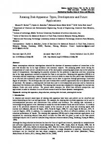
Figure 1: Radial stress (𝑇𝑟𝑟 ) and circumferential stress (𝑇𝜃𝜃 ) for annular disk with exponentially variable thickness and exponentially variable density with 𝑛 = 0.7, 0.2, 0.5 and 𝑚 = 0.7, 0.1, 0.5 under (a) 500 rad/s and (b) 780 rad/s for both approaches.
exponential variable thickness and exponential variable density with nonlinear strain hardening material behavior.
The equation of compatibility can be derived from (3) as follows: 𝑟
2. Mathematical Formulation Assuming that the stresses vary over the thickness of the disk, the theory of the disks of variable thickness can give good result as that of the disks of constant thickness as long as they meet the assumption of plane stress. For disk profile, it is assumed that disk is symmetric with respect to the mid plane. This profile is defined by the thickness function ℎ(𝑟) and density function 𝜌(𝑟) 𝑛
ℎ (𝑟) = ℎ0 𝑒−𝑘(𝑟/𝑏) ;
𝑚
𝜌 (𝑟) = 𝜌0 𝑒𝑡(𝑟/𝑏) ,
(1)
where 𝑛, 𝑚, 𝑘 and 𝑡 are geometric parameters, 𝑏 is the radius of the disk, ℎ0 is the thickness at the axis of the disk, and 𝜌0 is the density of the material.
𝑒𝑟𝑒 =
1 (2 (𝜆 + 𝜇) 𝑇𝑟𝑟 − 𝜆𝑇𝜃𝜃 ) ; 2𝜇 (3𝜆 + 2𝜇)
𝑒𝜃𝑒 =
1 (2 (𝜆 + 𝜇) 𝑇𝜃𝜃 − 𝜆𝑇𝑟𝑟 ) , 2𝜇 (3𝜆 + 2𝜇)
𝑒𝑟 =
𝑑𝑢 ; 𝑑𝑟
𝑒𝜃 =
𝑢 , 𝑟
(3)
where 𝑢 is the displacement component in the radial direction, 𝑒𝑟 is the radial strain, and 𝑒𝜃 is the circumferential strain.
(5)
where 𝑒𝑟𝑒 , 𝑒𝜃𝑒 are the elastic radial and circumferential strains, and 𝜆 and 𝜇 are Lame’s constants. For plastic deformation, the relation between the stresses and plastic strains can be determined according to the deformation theory of plasticity [3] 𝑒𝑟𝑝 =
(2)
where 𝑟 is the radial coordinate, 𝑇𝑟𝑟 and 𝑇𝜃𝜃 are the radial and circumferential stresses, and 𝜔 is the angular velocity of the disk. The strains and radial displacement are
(4)
The relations between stresses and elastic strains for plane stress problems can be determined according to theory of elasticity
2.1. Basic Equations. For rotating disk with variable thickness and variable density, the governing equilibrium equation is 𝑑 (ℎ𝑟𝑇𝑟𝑟 ) − ℎ𝑇𝜃𝜃 + ℎ𝜌𝜔2 𝑟2 = 0, 𝑑𝑟
𝑑𝑒𝜃 + 𝑒𝜃 − 𝑒𝑟 = 0. 𝑑𝑟
𝑝 𝑒𝜃
𝑒𝑒𝑝 1 (𝑇𝑟𝑟 − 𝑇𝜃𝜃 ) ; 𝑇𝑒𝑒 2
(6)
𝑒𝑝 1 = 𝑒 (𝑇𝜃𝜃 − 𝑇𝑟𝑟 ) , 𝑇𝑒𝑒 2
𝑝
where 𝑒𝑟𝑝 and 𝑒𝜃 are the plastic radial and circumferential strains, 𝑒𝑒𝑝 is the equivalent plastic strain, and 𝑇𝑒𝑒 is the equivalent stress. The Von-Mises yield criterion is given by 𝑇𝑒𝑒 = 2 − 𝑇 𝑇 + 𝑇2 . √𝑇𝑟𝑟 𝑟𝑟 𝜃𝜃 𝜃𝜃 The total strains are the sum of elastic and plastic strain
𝑒𝑟 = 𝑒𝑟𝑒 + 𝑒𝑟𝑝 ;
𝑝
𝑒𝜃 = 𝑒𝜃𝑒 + 𝑒𝜃 .
(7)
Journal of Materials ×108 4 3.5
3 ×10⁸ 3.5
Plot of stresses, 𝑘 = 1, 𝑡 = 0.5, 𝑚 = 0.1, ang. vel. = 500 (𝑇𝜃𝜃 )
(𝑇𝜃𝜃 )
3
1
(𝑇𝑟𝑟 )
Stresses
Stresses
1.5
(𝑇𝑟𝑟 )
(𝑇𝑟𝑟 )
2.5 (𝑇𝑟𝑟 )
(𝑇𝑟𝑟 )
1.5
(𝑇𝑟𝑟 )
1 0.5
0.5 0
(𝑇𝜃𝜃 ) (𝑇𝜃𝜃 )
2
2 2.5
(𝑇𝜃𝜃 )
3
(𝑇𝜃𝜃 )
Plot of stresses, 𝑘 = 1, 𝑡 = 0.5, 𝑚 = 0.5, ang. vel. = 500
0.1
0.15
0.2
0.25
0.3 𝑟
0.35
0.4
0.45
0
0.5
0.1
𝑛 = 0.7 RKM
FDM 𝑛 = 0.2 𝑛 = 0.5
0.15
0.2
0.25
0.3 𝑟
0.35
0.4
0.45
0.5
𝑛 = 0.7 RKM
FDM 𝑛 = 0.2 𝑛 = 0.5
(a)
(b)
×10 3.5 3
8
Plot of stresses, 𝑘 = 1, 𝑡 = 0.5, 𝑚 = 0.7, ang. vel. = 500 (𝑇𝜃𝜃 )
(𝑇𝜃𝜃 ) (𝑇𝜃𝜃 )
Stresses
2 2.5 1.5
(𝑇𝑟𝑟 )
(𝑇𝑟𝑟 ) (𝑇𝑟𝑟 )
1 0.5 0 0.1
0.15
0.2
0.25
0.3 𝑟
0.35
0.4
0.45
0.5
𝑛 = 0.7 RKM
FDM 𝑛 = 0.2 𝑛 = 0.5 (c)
Figure 2: Radial stress (𝑇𝑟𝑟 ) and circumferential stress (𝑇𝜃𝜃 ) for annular disk with exponentially variable thickness and exponentially variable density with (a) 𝑛 = 0.7, 0.2, 0.5 and 𝑚 = 0.1, (b) 𝑛 = 0.7, 0.2, 0.5, and 𝑚 = 0.5 (c) 𝑛 = 0.7, 0.2, 0.5 and 𝑚 = 0.7, under 500 rad/s for both approaches.
Let us now introduce a stress function 𝜙 and assume that the relations between stresses and the stress function are 𝑇𝑟𝑟 =
1 𝜙; ℎ𝑟
𝑇𝜃𝜃 =
1 𝑑𝜙 + 𝜌𝜔2 𝑟2 . ℎ 𝑑𝑟
(8)
Substituting (8) into (5), and further substitution into (7), one obtains
𝑒𝑟 =
𝜙 𝜙 1 (2 (𝜆 + 𝜇) − 𝜆 − 𝜆𝜌𝜔2 𝑟2 ) + 𝑒𝑟𝑝 , ℎ𝑟 ℎ 2𝜇 (3𝜆 + 2𝜇)
𝑒𝜃 =
𝜙 𝜙 1 𝑝 (2 (𝜆 + 𝜇) ( + 𝜌𝜔2 𝑟2 ) − 𝜆 ) + 𝑒𝜃 , ℎ ℎ𝑟 2𝜇 (3𝜆 + 2𝜇) (9)
where 𝜙 = 𝑑𝜙/𝑑𝑟. By the substitution of (9) into (1), we have 𝑟 𝑛 2 (𝜆 + 𝜇) 𝑟2 𝜙 + 2 (𝜆 + 𝜇) (1 + 𝑘𝑛( ) ) 𝑟𝜙 𝑏 𝑟 𝑛 − (2 (𝜆 + 𝜇) + 𝜆𝑘𝑛( ) ) 𝜙 𝑏
4
Journal of Materials ×108 Plot of stresses, 𝑘 = 1, 𝑡 = 0.5, 𝑚 = 0.7, angular velocity = 500 3.5
×108 Plot of stresses, 𝑘 = 1, 𝑡 = 0.5, 𝑛 = 0.2, angular velocity = 500 4 3.5 (𝑇 ) 𝜃𝜃
3
(𝑇𝜃𝜃 )
3
(𝑇𝑟𝑟 )
Stresses
Stresses
2.5
1.5
(𝑇𝑟𝑟 )
2 1.5 1
(𝑇𝑟𝑟 )
1
0.5
0.5 0 0.1
0.15
0.2
(𝑇𝜃𝜃 )
2.5
(𝑇𝜃𝜃 )
2
(𝑇𝜃𝜃 )
(𝑇𝜃𝜃 )
0.25
0.3 𝑟
FDM 𝑚 = 0.1 𝑚 = 0.5
0.35
0.4
0.45
0 0.1
0.5
(𝑇𝑟𝑟 )
(𝑇𝑟𝑟 )
(𝑇𝑟𝑟 )
0.15
0.2
0.25
0.3 𝑟
0.4
0.45
0.5
𝑛 = 0.7 RKM
FDM 𝑛 = 0.2 𝑛 = 0.5
𝑚 = 0.7 RKM
0.35
(a)
(b)
×108 Plot of stresses, 𝑘 = 1, 𝑡 = 0.5, 𝑛 = 0.7, angular velocity = 500 3.5 3
(𝑇𝜃𝜃 )
(𝑇𝜃𝜃 ) (𝑇𝜃𝜃 )
2.5 Stresses
2 1.5
(𝑇𝑟𝑟 )
(𝑇𝑟𝑟 )
1 (𝑇𝑟𝑟 )
0.5 0 0.1
0.15
0.2
0.25
0.3 𝑟
FDM 𝑚 = 0.1 𝑚 = 0.5
0.35
0.4
0.45
0.5
𝑚 = 0.7 RKM (c)
Figure 3: Radial stress (𝑇𝑟𝑟 ) and circumferential stress (𝑇𝜃𝜃 ) for annular disk with exponentially variable thickness and exponentially variable density with (a) 𝑚 = 0.1, 0.5, 0.7 and 𝑛 = 0.2, (b) 𝑚 = 0.1, 0.5, 0.7 and 𝑛 = 0.5, and (c) 𝑚 = 0.1, 0.5, 0.7 and 𝑛 = 0.7, 500 rad/s for both approaches.
+ 2𝜇 (3𝜆 + 2𝜇) ℎ0 𝑒−𝑘(𝑟/𝑏)
𝑛
By the nonlinear strain-hardening material model proposed by You and Zhang [8], the stress-strain relationship can be written as
𝑝
𝑑𝑒 𝑝 × 𝑟 (𝑟 𝜃 + 𝑒𝜃 − 𝑒𝑟𝑝 ) 𝑑𝑟 = − (7𝜆 + 6𝜇) ℎ0 𝜌0 × 𝑒𝑡(𝑟/𝑏) − 2 (𝜆 + 𝜇) ℎ0 𝜌0 𝑒𝑡(𝑟/𝑏)
𝑚
𝑚
−𝑘(𝑟/𝑏)𝑛
−𝑘(𝑟/𝑏)𝑛
𝜔2 𝑟3
𝑟 𝑚 𝑚𝑡( ) 𝜔2 𝑟3 , 𝑏
𝑒𝑒 =
(𝜆 + 𝜇) 𝑇𝑒𝑒 , 𝜇 (3𝜆 + 2𝜇)
𝑒𝑒 ≤ 𝑒0 ;
𝑒𝑒𝑝
3 𝑎1 𝑇𝑒𝑒
𝑒𝑒 > 𝑒0 ,
=
+
5 𝑎2 𝑇𝑒𝑒 ,
(11)
(10) where 𝜙 = 𝑑2 𝜙/𝑑𝑟2 , 𝜙 = 𝑑𝜙/𝑑𝑟.
where 𝑒𝑒 is the equivalent total strain and 𝑒0 the yield strain and 𝑎1 , 𝑎2 are material constants.
Journal of Materials ×108 2.5
(𝑇𝜃𝜃 ) (𝑇𝜃𝜃 )
1
4 (𝑇𝜃𝜃 )
(𝑇𝑟𝑟 )
(𝑇𝑟𝑟 )
0 0.1
0.15
0.2
(𝑇𝜃𝜃 ) (𝑇𝜃𝜃 )
3
(𝑇𝜃𝜃 )
1 0.25
0.3 𝑟
0.35
0.4
0.45
0.5
𝑚 = 0.7, 𝑛 = 0.7 RKM
FDM 𝑚 = 0.1, 𝑛 = 0.2 𝑚 = 0.5, 𝑛 = 0.5
0
(𝑇𝑟𝑟 )
(𝑇𝑟𝑟 )
2
(𝑇𝑟𝑟 )
0.5
Plot of stresses, angular velocity = 780
5
Stresses
Stresses
×108 6
Plot of stresses, angular velocity = 500
2 1.5
5
(𝑇𝑟𝑟 ) 0.1
0.15
0.2
0.25
0.3 𝑟
0.4
0.45
0.5
𝑚 = 0.7, 𝑛 = 0.7 RKM
FDM 𝑚 = 0.1, 𝑛 = 0.2 𝑚 = 0.5, 𝑛 = 0.5
(a)
0.35
(b)
Figure 4: Radial stress (𝑇𝑟𝑟 ) and circumferential stress (𝑇𝜃𝜃 ) for annular disk with variable thickness and variable density with 𝑛 = 0.2, 0.5, 0.7 and 𝑚 = 0.1, 0.5, 0.7 under (a) 500 rad/s and (b) 780 rad/s for both approaches.
Substitution of the second equation of (11) into (6), the plastic strains can be written as
𝑒𝑟𝑝 = 𝑝
𝑒𝜃 =
3 5 (𝑎1 𝑇𝑒𝑒 + 𝑎2 𝑇𝑒𝑒 )
𝑇𝑒𝑒 3 5 (𝑎1 𝑇𝑒𝑒 + 𝑎2 𝑇𝑒𝑒 )
𝑇𝑒𝑒
1 (𝑇𝑟𝑟 − 𝑇𝜃𝜃 ) ; 2
(12)
1 (𝑇𝜃𝜃 − 𝑇𝑟𝑟 ) . 2
The governing equation in the plastic region of the rotating disks in terms of stresses and stress function can be obtained by substituting (12) into (10) as
− 2𝜇 (3𝜆 + 2𝜇) 1 2 ) (2𝑇𝜃𝜃 − 𝑇𝑟𝑟 ) × { (𝑎1 + 2𝑎2 𝑇𝑒𝑒 2 𝑟 𝑛 × {(2𝑇𝑟𝑟 − 𝑇𝜃𝜃 ) [𝑟𝜙 − (1 − 𝑘𝑛( ) ) 𝜙] 𝑏 + (2𝑇𝜃𝜃 − 𝑇𝑟𝑟 ) 𝑚 𝑛 𝑟 𝑛 × (𝑟𝑘𝑛( ) 𝜙 + 2ℎ0 𝜌0 𝑒𝑡(𝑟/𝑏) −𝑘(𝑟/𝑏) 𝜔2 𝑟3 𝑏
+ℎ0 𝜌0 𝑒𝑡(𝑟/𝑏)
𝑚
−𝑘(𝑟/𝑏)𝑛
𝑟 𝑚 𝑚𝑡( ) 𝜔2 𝑟3 )} 𝑏
2 4 + 𝑎2 𝑇𝑒𝑒 ) + (𝑎1 𝑇𝑒𝑒
{2 (𝜆 + 𝜇) + 2𝜇 (3𝜆 + 2𝜇)
1 1 𝑟 𝑛 𝑟 𝑛 × {− ( − 𝑘𝑛( ) ) 𝑟𝜙 + (1 − 𝑘𝑛( ) ) 𝜙 2 𝑏 2 𝑏
1 2 2 × [ (𝑎1 + 2𝑎2 𝑇𝑒𝑒 ) (2𝑇𝜃𝜃 − 𝑇𝑟𝑟 ) 2
+ 2ℎ0 𝜌0 𝑒𝑡(𝑟/𝑏)
2 4 + (𝑎1 𝑇𝑒𝑒 + 𝑎2 𝑇𝑒𝑒 ) ]} 𝑟2 𝜙
+ ℎ0 𝜌0 𝑒𝑡(𝑟/𝑏)
𝑟 𝑛 = −2 (𝜆 + 𝜇) (1 + 𝑘𝑛( ) ) 𝑟𝜙 𝑏
− 2 (𝜆 + 𝜇) ℎ0 𝜌0 𝑒𝑡(𝑟/𝑏)
𝑚
𝑚
−𝑘(𝑟/𝑏)𝑛
𝜔2 𝑟3
𝑟 𝑚 𝑚𝑡( ) 𝜔2 𝑟3 𝑏
(13)
−𝑘(𝑟/𝑏)𝑛
−𝑘(𝑟/𝑏)𝑛
−𝑘(𝑟/𝑏)𝑛
𝑛 3 + 𝑟ℎ0 𝑒−𝑘(𝑟/𝑏) (𝑇𝜃𝜃 − 𝑇𝑟𝑟 )}} . 2
𝑟 𝑛 + (2 (𝜆 + 𝜇) + 𝜆𝑘𝑛( ) ) 𝜙 𝑏 − (7𝜆 + 6𝜇) ℎ0 𝜌0 𝑒𝑡(𝑟/𝑏)
𝑚
𝑚
𝜔2 𝑟3
𝑟 𝑚 𝑚𝑡( ) 𝜔2 𝑟3 𝑏
The values of the stress function 𝜙 at the elastic-plastic interface radius are the same, and, therefore, the stress function 𝜙 is continuous at the interface radius [9]. It can be seen from the continuity of the stress function and (3),
6
Journal of Materials ×108 2.5
×108 2
Plot of stresses, 𝑚 = 0.1, angular velocity = 500
1.8 1.6
(𝑇𝜃𝜃 ) (𝑇𝜃𝜃 )
1
(𝑇𝜃𝜃 )
(𝑇𝜃𝜃 )
1.4
1.5
Stresses
Stresses
2 (𝑇 ) 𝜃𝜃
Plot of stresses, 𝑚 = 0.5, angular velocity = 500
(𝑇𝑟𝑟 )
(𝑇𝑟𝑟 )
1
(𝑇𝑟𝑟 )
(𝑇𝑟𝑟 )
0.8 0.6
(𝑇𝑟𝑟 )
0.5
(𝑇𝜃𝜃 )
1.2
(𝑇𝑟𝑟 )
0.4 0.2
0
0.1
0.15
0.2
0.25
0.3 𝑟
FDM 𝑛 = 0.2 𝑛 = 0.5
0.35
0.4
0.45
0
0.5
0.15
0.1
𝑛 = 0.7 RKM
0.2
0.25
FDM 𝑛 = 0.2 𝑛 = 0.5
0.3 𝑟
0.35
0.4
0.45
0.5
𝑛 = 0.7 RKM
(a)
(b)
×107 18 16
Plot of stresses, 𝑚 = 0.7, angular velocity = 500 (𝑇𝜃𝜃 )
(𝑇𝜃𝜃 )
14
Stresses
12
(𝑇𝜃𝜃 )
10
(𝑇𝑟𝑟 )
(𝑇𝑟𝑟 )
8 6 4
(𝑇𝑟𝑟 )
2 0
0.1
0.15
0.2
0.25
0.3 𝑟
FDM 𝑛 = 0.2 𝑛 = 0.5
0.35
0.4
0.45
0.5
𝑛 = 0.7 RKM (c)
Figure 5: Radial stress (𝑇𝑟𝑟 ) and circumferential stress (𝑇𝜃𝜃 ) for annular disk with variable thickness and variable density with (a) 𝑛 = 0.7, 0.2, 0.5 and 𝑚 = 0.1, (b) 𝑛 = 0.7, 0.2, 0.5 and 𝑚 = 0.5, and (c) 𝑛 = 0.7, 0.2, 0.5 and 𝑚 = 0.7, under 500 rad/s for both approaches.
(5)–(7), and (8) that the continuity conditions of the stresses and displacements at the elastic-plastic interface radius are satisfied. The boundary conditions for the rotating annular disks are
𝑇𝑟𝑟 = 0
at 𝑟 = 𝑎;
𝑇𝑟𝑟 = 0
at 𝑟 = 𝑏,
(14)
where 𝑎 and 𝑏 are the inner and outer radii of the rotating disks, respectively.
3. Finite Difference Algorithm To determine the elastic-plastic stresses, strains, and displacement in thin rotating disks with a nonlinear strain hardening material, we have to solve the second-order nonlinear differential equation (13) under the given boundary condition (14). The general form of (13) can be written as 𝜙 = 𝑓 (𝑟, 𝜙, 𝜙 ) .
(15)
3.1. Finite Difference Algorithm Steps. The second-order differential equation (13) with the given boundary conditions can be solved by using finite difference method.
Journal of Materials ×108 2.5
7 ×10⁷ 18
Plot of stresses, 𝑛 = 0.2, angular velocity = 500
Plot of stresses, 𝑛 = 0.5, angular velocity = 500
16 (𝑇𝜃𝜃 ) (𝑇𝜃𝜃 )
2 (𝑇 ) 𝜃𝜃
14
1 0.5 0 0.1
(𝑇𝜃𝜃 )
Stresses
Stresses
12 1.5 (𝑇𝑟𝑟 )
(𝑇𝑟𝑟 )
10
(𝑇𝑟𝑟 )
(𝑇𝑟𝑟 )
8 6 4
(𝑇𝑟𝑟 ) 0.15
(𝑇𝜃𝜃 )
(𝑇𝜃𝜃 )
(𝑇𝑟𝑟 )
2 0.2
0.25
0.3 𝑟
0.35
0.4
0.45
0 0.1
0.5
0.15
0.25
0.3 𝑟
FDM 𝑚 = 0.1 𝑚 = 0.5
𝑚 = 0.7 RKM
FDM 𝑚 = 0.1 𝑚 = 0.5
0.2
0.35
0.4
0.45
0.5
𝑚 = 0.7 RKM
(a)
(b)
×107 18 16 14
Plot of stresses, 𝑛 = 0.7, angular velocity = 500 (𝑇𝜃𝜃 )
(𝑇𝜃𝜃 )
Stresses
12 10 8
(𝑇𝜃𝜃 )
(𝑇𝑟𝑟 )
(𝑇𝑟𝑟 )
6 4
(𝑇𝑟𝑟 )
2 0 0.1
0.15
0.2
0.25
0.3 𝑟
FDM 𝑚 = 0.1 𝑚 = 0.5
0.35
0.4
0.45
0.5
𝑚 = 0.7 RKM (c)
Figure 6: Radial stress (𝑇𝑟𝑟 ) and circumferential stress (𝑇𝜃𝜃 ) for annular disk with variable thickness and variable density with (a) 𝑚 = 0.1, 0.5, 0.7 and 𝑛 = 0.2, (b) 𝑚 = 0.1, 0.5, 0.7 and 𝑛 = 0.5, and (c) 𝑚 = 0.1, 0.5, 0.7 and 𝑛 = 0.7, under 500 rad/s for both approaches.
(i) First, partition the domain [0.1 0.5] into 𝑝 subintervals of length ℎ. (ii) To express the differential operators 𝑑𝜙/𝑑𝑟 and 𝑑2 𝜙/𝑑𝑟2 in a discrete form, we use the finite difference approximations as 𝑑2 𝜙 𝜙𝑖+1 − 2𝜙𝑖 + 𝜙𝑖−1 = , 𝑑𝑟2 ℎ2
𝑑𝜙 𝜙𝑖+1 − 𝜙𝑖−1 = . 𝑑𝑟 2ℎ
(16)
(iii) With ℎ = 1/𝑝, we have 𝑝 + 1 nodal points 𝜙1 , 𝜙2 , . . . , 𝜙𝑝+1 . The values at the end points are given by the boundary conditions; that is, we are given that 𝜑1 = 0, 𝜑𝑝+1 = 0. Using the finite
difference approximation, we get the following system of equations: 𝜙𝑖+1 − 2𝜙𝑖 + 𝜙𝑖−1 ℎ2 𝜙 − 𝜙𝑖−1 = 𝑓 (𝑟, 𝜙𝑖 , 𝑖+1 ), 2ℎ
(17) 𝑖 = 2, 3, . . . , 𝑛.
(iv) After simplifying and collecting coefficients of 𝜙𝑖+1 , 𝜙𝑖 , and 𝜙𝑖−1 , in Step 3, the boundary value problem results in system of nonlinear equations. (v) The solution of the (𝑝 − 1) system of nonlinear equations can be obtained using Newton-Raphson’s
8
Journal of Materials ×108 2.5
(𝑇𝜃𝜃 )
2
Plot of stresses, angular velocity = 780
5 4
1.5
Stresses
Stresses
×108 6
Plot of stresses, angular velocity = 500
(𝑇𝑟𝑟 )
1
3 2
0.5 0 0.1
1 0.15
0.2
0.25
0.3 𝑟
0.35
0.4
0.45
0.5
FDM 𝑛 = 0, 𝑚 = 0 RKM
0 0.1
0.15
0.2
0.25
0.3 𝑟
0.35
0.4
0.45
0.5
FDM 𝑛 = 0, 𝑚 = 0 RKM (a)
(b)
Figure 7: Radial stress (𝑇𝑟𝑟 ) and circumferential stress (𝑇𝜃𝜃 ) for annular disk with constant thickness and constant density under (a) 500 rad/s and (b) 780 rad/s for both approaches.
method where the unknowns are 𝜙2 , 𝜙3 , . . . , 𝜙𝑝−1 . By this process, we will get the stress function and then stresses, strains, and displacement.
4. Numerical Illustration and Discussion A two-dimensional plane stress analysis of rotating disk with nonuniform thickness and nonuniform density are carried out using finite difference method. The radius of the rotating disk is taken to be 𝑏 = 0.5, and its materials properties are material density 𝜌 = 8000 Kg/m3 , Lame’s constant are 𝜆 = 79.61 GPa, 𝜇 = 119.42 GPa, and Poisson’s ratio ] = 0.3. 4.1. Rotating Annular Disk with Exponentially Variable Thickness and Exponentially Variable Density. It has been observed from Figures 1(a) and 1(b) that as thickness decreases and density increases radially, circumferential stress is going on decreasing. Also, circumferential stress is maximum at the internal surface. With the increase in angular velocity, circumferential stress is going on increasing. Figures 2(a), 2(b) and 2(c) are sketched for uniform density and we observed that circumferential stresses are maximum at internal surface and these stresses decreases with decrease in thickness radially. As with the increase in density radially, circumferential goes on decreasing which gives appropriate design of the disk. It has been observed from Figures 3(a), 3(b), and 3(c) that for uniform thickness, circumferential stress is maximum at internal surface. Also, circumferential stress for the disk whose density decreases radially is maximum as compared to the disk with high density. Also, decrease in thickness radially yields decrease in circumferential stress, which gives appropriate design of disk. From all previous analysis, we can conclude that disk whose thickness decreases radially and density increases
radially is on the safer side of the design as compared to other thickness and density parameters, because circumferential stress is less for the disk whose thickness decreases radially and density increases radially as compared to other thickness and density parameters. 4.2. Rotating Annular Disk with Variable Thickness and Variable Density Using Power Law (ℎ = ℎ0 (𝑟/𝑏)−𝑛 ; 𝜌 = 𝜌0 (𝑟/𝑏)𝑚 ). It has been observed from Figures 4(a) and 4(b) that circumferential stress is maximum at internal surface. Circumferential stress is maximum for the disk whose density is less and thickness is high as compared to the disk whose thickness is less and density is high. Also, it has been observed from the figure that with the increase in angular speed, circumferential stress goes on increasing, but again circumferential stress is less as compared to other cases. It has been observed from Figures 5(a), 5(b), and 5(c) that for uniform density disk, circumferential stress is maximum at internal surface. With the decrease in thickness radially, circumferential stress goes on decreasing. Also with the increase in density, circumferential stress further decreases which provides an appropriate design of the disk. It has been observed from Figures 6(a), 6(b), and 6(c) that for uniform thickness, circumferential stresses are maximum at internal surface. Also, it has been noted that circumferential stress is less for disk profile with high density as compared to disk profiles with less density. With the decrease in thickness radially, circumferential stress decreases which yields that disk, whose thickness is less and density is high, is appropriate for the design as compared to other disk profiles. From the previous analysis, we observed that disk with high density and less thickness is on the safer side of the design as compared to other parameters because circumferential stress is less for previous case as compared to other
Journal of Materials disk profiles. The results calculated for variable thickness and variable density (ℎ = ℎ0 (𝑟/𝑏)−𝑛 ; 𝜌 = 𝜌0 (𝑟/𝑏)𝑚 ) using finite difference method are in very good agreement with RungeKutta’s method studied by You et. al [9] for all the rotating disks. 4.3. Annular Disk with Constant Thickness and Constant Density. It has been observed from Figures 7(a) and 7(b) that for constant thickness and constant density, circumferential stress is maximum at internal surface. Also, with the increase in angular speed, circumferential stress increases significantly.
5. Conclusion After analyzing all the three disk profiles, it can be concluded that circumferential stresses are maximum at internal surface. It is also concluded that disk whose thickness decreases radially and density increases radially is on the safer side of design as compared to the disk with exponentially varying thickness and exponentially varying density as well as to flat disk. This is because circumferential stresses for the disks whose thickness decreases and density increases radially are less as compared to the disk with exponentially varying thickness and exponentially varying density as well as to flat disk.
References [1] S. P. Timoshenko and J. N. Goodier, Theory of Elasticity, McGraw-Hill, New York, NY, USA, 3rd edition, 1970. [2] S. C. Ugural and S. K. Fenster, Advanced Strength and Applied Elasticity, Elsevier, New York, NY, USA, 1987. [3] R. Hill, The Mathematical Theory of Plasticity, Oxford University Press, Oxford, UK, 1998. [4] S. Sharama, M. Sahni, and R. Kumar, “Elastic-plastic analysis of a thin rotating disk of exponentially variable thickness with inclusion,” WSEAS Transactions on Mathematics, vol. 9, no. 5, pp. 314–323, 2010. [5] U. Gamer, “Elastic-plastic deformation of the rotating solid disk,” Ingenieur-Archiv, vol. 54, no. 5, pp. 345–354, 1984. [6] U. G¨uven, “Elastic-plastic stresses in a rotating annular disk of variable thickness and variable density,” International Journal of Mechanical Sciences, vol. 34, no. 2, pp. 133–138, 1992. [7] L. H. You, S. Y. Long, and J. J. Zhang, “Perturbation solution of rotating solid disks with nonlinear strain-hardening,” Mechanics Research Communications, vol. 24, no. 6, pp. 649–658, 1997. [8] L. H. You and J. J. Zhang, “Elastic-plastic stresses in a rotating solid disk,” International Journal of Mechanical Sciences, vol. 41, no. 3, pp. 269–282, 1999. [9] L. H. You, Y. Y. Tang, J. J. Zhang, and C. Y. Zheng, “Numerical analysis of elastic-plastic rotating disks with arbitrary variable thickness and density,” International Journal of Solids and Structures, vol. 37, no. 52, pp. 7809–7820, 2000. [10] S. C. Sterner, S. Saigal, W. Kistler, and D. E. Dietrich, “A unified numerical approach for the analysis of rotating disks including turbine rotors,” International Journal of Solids and Structures, vol. 31, no. 2, pp. 269–277, 1994.
9
Journal of
Nanotechnology Hindawi Publishing Corporation http://www.hindawi.com
Volume 2014
International Journal of
International Journal of
Corrosion Hindawi Publishing Corporation http://www.hindawi.com
Polymer Science Volume 2014
Hindawi Publishing Corporation http://www.hindawi.com
Volume 2014
Smart Materials Research Hindawi Publishing Corporation http://www.hindawi.com
Journal of
Composites Volume 2014
Hindawi Publishing Corporation http://www.hindawi.com
Volume 2014
Journal of
Metallurgy
BioMed Research International Hindawi Publishing Corporation http://www.hindawi.com
Volume 2014
Nanomaterials
Hindawi Publishing Corporation http://www.hindawi.com
Volume 2014
Submit your manuscripts at http://www.hindawi.com Journal of
Materials Hindawi Publishing Corporation http://www.hindawi.com
Volume 2014
Journal of
Nanoparticles Hindawi Publishing Corporation http://www.hindawi.com
Volume 2014
Nanomaterials Journal of
Advances in
Materials Science and Engineering Hindawi Publishing Corporation http://www.hindawi.com
Volume 2014
Journal of
Hindawi Publishing Corporation http://www.hindawi.com
Volume 2014
Journal of
Nanoscience Hindawi Publishing Corporation http://www.hindawi.com
Scientifica
Hindawi Publishing Corporation http://www.hindawi.com
Volume 2014
Journal of
Coatings Volume 2014
Hindawi Publishing Corporation http://www.hindawi.com
Crystallography Volume 2014
Hindawi Publishing Corporation http://www.hindawi.com
Volume 2014
The Scientific World Journal Hindawi Publishing Corporation http://www.hindawi.com
Volume 2014
Hindawi Publishing Corporation http://www.hindawi.com
Volume 2014
Journal of
Journal of
Textiles
Ceramics Hindawi Publishing Corporation http://www.hindawi.com
International Journal of
Biomaterials
Volume 2014
Hindawi Publishing Corporation http://www.hindawi.com
Volume 2014