arXiv:physics/0011069v1 [physics.comp-ph] 29 Nov 2000. Finite element approach for simulating quantum electron dynamics in a magnetic field.
Finite element approach for simulating quantum electron dynamics in a magnetic field Naoki Watanabe, Masaru Tsukada
arXiv:physics/0011069v1 [physics.comp-ph] 29 Nov 2000
Department of Physics,Graduate School of Science, University of Tokyo 7-3-1 Hongo, 113-0033 Bunkyo-ku, Tokyo, Japan (Published from Journal of Physical Society of Japan, 69, No.9, 2962, (2000).) A fast and stable numerical method is formulated to compute the time evolution of a wave function in a magnetic field by solving the time-dependent Schr¨ odinger equation. This computational method is based on the finite element method in real space to improved accuracy without any increase of computational cost. This method is also based on Suzuki’s exponential product theory to afford an efficient way to manage the TD-Schr¨ odinger equation with a vector potential. Applying this method to some simple electron dynamics, we have confirmed its efficiency and accuracy. 02.70.-c,03.67.Lx,73.23,42.65.-k
I. INTRODUCTION
II. FORMULATION
Conventionally, wave functions have been represented as a linear combination of plane waves or atomic orbitals in the calculations of the electronic states or their time evolution. However, these representations entail high computational cost to calculate the matrix elements for these bases. The plane wave bases set is not suitable for localized orbitals, and the atomic orbital bases set is not suitable for spreading waves. To overcome those problems, some numerical methods adopted real-space representation to solve the time dependent Schr¨odinger equation [1–4]. In those methods, a wavefunction is descritized by grid points in real space and the spatial differential operator is approximated by the finite difference method (FDM). With those methods, some dynamic electron phenomena were simulated successfully [7–9]. In the previous work [11], we have formulated a new computational method for the TD-Schr¨odinger equation by using some computational techniques such as, the FDM, Suzuki’s exponential product theory [12–17], Cayley’s form [6] and Adhesive operator. This method afforded high-stability and low computational cost. In the field of engineering, for example, numerical analysis of fluid dynamics or of strength of macroscopic constructions, the finite element method (FEM) has been widely and traditionally used for approximating the appropriate partial differential equations. Recently, the FEM has been found useful for the time-independent Schr¨odinger equation of electrons in solid or liquid materials [10]. In this paper, we have utilized the FEM for solving the TD-Schr¨odinger equation as an extension of the previous work [11]. By using Cayley’s form and the FEM, this method affords high-accuracy without any increase of computational cost. Moreover, we have formulated a new efficient method which manages the time evolution of a wave function in a vector potential or in a magnetic field. These techniques are especially useful for simulating dynamics of electrons in a variety of meso-scopic systems.
In this section, we formulate a new method derived by the FEM and a new scheme to manage a vector potential efficiently. Throughout this paper, we often use the atomic unit h ¯ = 1, m = 1, e = 1.
A. FEM for the TD-Schr¨ odinger equation
First, we utilize the FEM for the time evolution of a wave function in a one-dimensional closed system described by the following TD-Schr¨odinger equation: i¯ h
¯h2 ∂ 2 ∂ψ(x, t) =− ψ(x, t) . ∂t 2m ∂x2
(1)
The FEM starts by smoothing the wavefunction around a grid point. We smoothed ψ(x) around a grid point xi by eq. (2), as illustrated in Fig. 1: 1 ψ(x, t) = ψi (t) + ψi′ (t)(x − xi ) + ψi′′ (t)(x − xi )2 , (2) 2 where ψi (t) ≡ ψ(xi , t) , ψi+1 (t) − ψi−1 (t) ψi′ (t) ≡ , 2∆x ψi+1 (t) − 2ψi (t) + ψi−1 (t) . ψi′′ (t) ≡ ∆x2
(3)
φi φ i-1
x i-1
φ i+1
xi
x i+1
FIG. 1. The FEM starts by smoothing the wavefunction around a grid point. The wavefunction is supplemented by a quadratic equation.
1
Using these notations, eq. (7) is expressed simply as
By substituting eq. (3) for eq. (2), ψ(x, t) is expressed as
∂ψ(t) ¯h2 D ψ(t) . (11) =− ∂t 2m∆x2 Equation (11) is the finite element equation for this case. It has been thought that the existence of the matrix S is troublesome since the inverse of this matrix is required to obtain the time derivative of the wave function, namely, i¯ hS
ψ(x, t) = uai (x) ψi−1 (t) + uoi (x) ψi (t) + ubi (x) ψi+1 (t) , (4) where uai (x), uoi (x) and ubi (x) are the base functions defined below: (x−xi) (x−xi)2 − , 2∆x2 2∆x (x−xi)2 , uoi (x) = 1 − ∆x2 (x−xi)2 (x−xi) ubi (x) = + . 2∆x2 2∆x uai (x) =
i¯ h ∂ψ(t) S−1 D ψ(t) . (12) = ∂t 2m∆x2 However, we have found that this differential equation is easily solved by using an approximation called Cayley’s form. The formal solution of eq. (12) is given by, h i¯ h ∆t −1 i ψ(t + ∆t) = exp S D ψ(t) . (13) 2m ∆x2 The exponential operator is approximated by Cayley’s form: i¯ h ∆t −1 I+ S D 4m ∆x2 ψ(t + ∆t) ≃ ψ(t) . (14) i¯ h ∆t −1 I− S D 4m ∆x2 Multiplying both the numerator and the denominator of the righthand side by the matrix S and using the relation (6), the required formula is obtained:
(5)
Substituting eq. (4) for eq. (1) and multiplying both side of the equation by the base function uoi (x) and integrating by x in the range [xi−1 , xi+1 ] as Z xi+1 h dx uoi (x) uoi (x) ψ˙ i (t) i¯ h xi−1
i + uai (x) ψ˙ i+1 (t) + ubi (x) ψ˙ i−1 (t) Z xi+1 h ¯2 h dx uoi (x) ∂x2 uoi (x) ψi (t) =− 2m xi−1 i + ∂x2 uai (x) ψi+1 (t) + ∂x2 ubi (x) ψi−1 (t) ,
(6)
i¯ h 4meff ψ(t + ∆t) = i¯ h I− 4m∗eff I+
the following formula is obtained after some algebra: � 1�˙ ψi−1 (t) + 8ψ˙ i (t) + ψ˙ i+1 (t) 10 � ¯h2 � =− ψi−1 (t) − 2ψi (t) + ψi+1 (t) . 2 2m∆x i¯ h
(7)
In this way, the solution of the partial differential equation, eq. (1) is computed by eq. (15) with the concept of the FEM. It is quite a remarkable result that formula eq. (15) is almost the same as the formula derived by the FDM [11]. In this time evolution, the norm of the wave function is exactly conserved since the time evolution operator appearing in eq. (1) is strictly unitary. Moreover, accuracy is dramatically improved without any increase in the computational cost, as demonstrated in the next section. It is easy to extend this idea for two-dimensional systems, since the time evolution operator in a twodimensional system is decomposed into a product of the time evolution operators in one-dimensional systems [11]. The approximated solution utilizing the FEM is given by
(8)
8 1 0 0 .. .. 1 1 . . 0 , S≡ 10 . . . . . . 1 0 0 0 1 8 −2 1 0 0 1 ... ... 0 . D≡ 0 ... ... 1 0 0 1 −2
(9)
i¯ h 4meff ψ(r, t + ∆t) = i¯ h I− 4m∗eff I+
Clearly S and D satisfy the following equation: S= I+
1 D. 10
(15)
where meff is an “effective mass” of an electron defined as ¯h 2 ∆x2 ¯h ≡ −i . (16) meff m 5 ∆t
To simplify the expression, it is useful to define a vector and two matrices as below: ψ(t) ≡ (ψ0 (t), . . . , ψN −1 (t))T ,
∆t D ∆x2 ψ(t) , ∆t D ∆x2
(10)
2
i¯ h ∆t Dx I + 4meff ∆x2 · i¯ h ∆t Dx I − ∆x2 4m∗eff
∆t Dy ∆y 2 ψ(r, t) , ∆t Dy ∆y 2 (17)
Moreover, we have found that the hybrid decomposition [17] is rather easy in this case. Note the following identity: �� � 2 � (24) ∂y , (∂x − iay)2 , ∂y2 = −8a2 ∂y2 .
where Dx and Dy are the finite difference matrices along the x and y axes respectively, and their appearances are the same as D defined in eq. (9).
B. Evolution in a magnetic field
Then, equation (21) is approximated by the following fourth-order hybrid exponential product:
Though there are many interesting phenomena in a magnetic field, there has been no efficient methods that numerically manage the dynamics in a magnetic field as far as we know. We have improved our method to afford an efficient way to solve the TD-Schr¨odinger equation with a vector potential given as below i¯ h
∂ψ(r, t) ie �2 h2 � ¯ ∇ − A ψ(r, t) . =− ∂t 2m h ¯
h i¯ h � 1 e2 B 2 ∆t2 � 2 i ψ(r, t + ∆t) = exp ∆t − ∂y 2m 6 72m2 c2 � h ∆t i¯ � ie � � ie h 2i ∂x exp − Bxy × exp + Bxy exp ¯h 2 2m ¯h h 2∆t i¯ h 2i × exp ∂ 3 2m y � ie � h ∆t i¯ � ie � h 2i × exp + Bxy exp ∂x exp − Bxy ¯h 2 2m ¯h h i¯ h � 1 e2 B 2 ∆t2 � 2 i ∂y ψ(r, t) + O(∆t5 ) . − × exp ∆t 2m 6 72m2 c2 (25)
(18)
In this subsection, we present the method for only the case of a two-dimensional system lying on the xy plane subjected to a uniform external magnetic field along the z axis. We do not mention the case of a non-uniform magnetic field specifically, but the extension of the method is straightforward. We adopt the following vector potential A for this magnetic field: A = (−By, 0, 0)T .
The exponential of the magnetic field just changes the phase of the wave function, so it is very easy to compute. Therefore, this method is adaptable to systems subjected to a magnetic field. The outline of the procedure for a two-dimensional system subjected to a magnetic field is schematically described by Fig. 2.
(19)
The TD-Schr¨odinger equation of this system is given by i¯ h
∂ψ(r, t) h ie �2 ¯2 � h ¯ 2 2i h ∂x − By − = − ∂ ψ(r, t) . ∂t 2m h ¯ 2m y (20) Ky
+Bxy
Kx
-Bxy
Ky
The strict, analytical solution is also given by an exponential operator:
FIG. 2. The procedure for a two-dimensional system subjected to a magnetic field. Here Bxy means the operation of i � h i¯ ie �2 h i¯ h the exponential of the magnetic field. In this way, the phase . the wavefunction is turned forward before the operation of ∆t ∂x − By + ∆t∂y2 ψ(r, t) of ψ(r, t + ∆t) = exp 2m h ¯ 2m Cayley’s form along the x-axis and is turned backward after (21) Cayley’s form.
Note the following identity: � � � ie � i¯ h� ie �2 exp ∆t = exp + Bxy ∂x − By 2m h ¯ h ¯ � � � ie � i¯ h 2 ∂x exp − Bxy . (22) × exp ∆t 2m h ¯
III. APPLICATIONS A. Comparison between FDM and FEM
In this subsection, we briefly compare Cayley’s form and other conventional methods by simply simulating a Gaussian wave packet moving in a one-dimensional free system as illustrated in Fig. 3.
Equation (21) is approximated by the following secondorder exponential product: �
� � ie � ∆t i¯ h 2 ψ(r, t + ∆t) = exp ∂y exp + Bxy 2 2m h ¯ � � � ie � i¯ h 2 ∂x exp − Bxy × exp ∆t 2m h ¯ � � h 2 ∆t i¯ ∂ ψ(r, t) + O(∆t3 ) . (23) × exp 2 2m y
po 2W
x xo
3
FIG. 3. The model system for comparison with the conventional methods. 256 computational grid points are allocated in the physical length 8.0a.u. A Gaussian wave packet is placed in the system, whose initial average location xo and momentum po are set as xo = 2.0a.u. and po = 12.0a.u., respectively.
We have simulated the motion of the Gaussian by those methods. Figure 4 shows the error in the average momentum. The errors are evaluated in the following way: hx(t = T )i − xo − po , T N −1 X xi |ψi (t)|2 in FDM. hx(t)i = ∆x ǫ(∆t/∆x2 ) =
The TD-Schr¨odinger equation of this system is simply given by ∂2 ∂ψ(x, t) = − x ψ(x, t) . i ∂t 2
N −1 X ∆x xi ψi∗ 24ψi + 4ψi+1 + 4ψi−1 hx(t)i = Re 30 i=0 � in FEM. (36) −ψi+2 − ψi−2
(26)
h |x − x |2 i o exp − + ip x , (27) o 4W 2 2πW 2 1
Error in the average momentum
0.1
where W = 0.25a.u. xo = 2.0a.u. po = 12.0a.u. The evolution of this Gaussian is analytically derived as 1
ψ(x, t) = p 4 2πW 2 + (π/2)(t/W )2 i h (x − x − p t)2 o o + ip x . × exp − o 4W 2 + (t/W )2
(28)
Therefore, the average location of the Gaussian hx(t)i is derived as if it is a classical particle: hx(t)i = hx(t = 0)i + po t .
1 + i∆t/4 ∂x2 ψ(t) , 1 − i∆t/4 ∂x2
(29)
−2 1 1 0 ∂x2 ≃ ∆x2 0 0 0
1 −2 1 0 0 0
0 1 −2 1 0 0
0 0 1 −2 1 0
0 0 0 1 −2 1
0 0 0 . 0 1 −2
meff + i∆t/4∂x2 ψ(t) , m∗eff − i∆t/4∂x2
-0.1 -0.2 -0.3 Cayley with FDM -0.4 -0.5
0.125
0.25
(30)
1
2
4
It is found that the accuracy is dramatically improved by using the FEM. It is remarkable that in spite of the improvement of accuracy, the computational cost does not increase at all. B. Cyclotron motion
(31)
We demonstrate the cyclotron motion in the framework of quantum mechanics. We have simulated the motion of a Gaussian wave packet in a uniform magnetic force as illustrated in Fig. 5.
(32)
B
where the spatial differential operator is approximated in the ordinary way and meff is the effective mass: 1 1 2 ∆x2 ≡ −i , meff m 5 ∆t
0.5
FIG. 4. The errors in the average momentum computed by Cayley’s form with the FDM and Cayley’s form with the FEM. The error of the FEM is smaller than that of the FDM. The spatial slice is set as ∆x = 1/32a.u.
Meanwhile, Cayley’s form with the FEM is given by ψ(t + ∆t) =
Cayley with FEM
∆ t / ∆x 2
where ∂x2 is approximated by a finite difference matrix as
0.0
-0.6 0.0625
This characteristic is useful to check the accuracy of the simulation. Cayley’s form with the FDM is given by ψ(t + ∆t) =
(35)
i=0
The wavefunction at the initial state is set as a Gaussian: ψ(x, t = 0) = √ 4
(34)
y
(33)
x
∂x2 is approximated by eq. (31). 4
FIG. 5. The model system for the cyclotron motion. This system is subjected to a static magnetic force perpendicularly. and it is surrounded by infinitely high potentials. 64 × 64 computational grid points are allocated in the physical length 8a.u. × 8a.u. The strength of the static magnetic force B is set as 2a.u. A Gaussian is placed as the initial state of the wavefunction, whose average location and momentum are set as (6a.u., 4a.u.) and (0a.u., 4a.u.), respectively. The time slice is set as ∆t = 1/64a.u.
The initial wavefunction ψ(r, t = 0) is set as the following Gaussian:
t=0
t=3/8
t=6/8
t=9/8
t=12/8
t=15/8
t=18/8
t=21/8
h |r − r |2 i h ieB i 1 o exp − ψ(r, t = 0) = √ exp (x − L/2)y , 4W 2 ¯h 2πW 2 (37)
where ro is set as xo = 6a.u., yo = 4a.u. and W is set as 0.5a.u. The initial density ρ(r, t = 0) and the initial current density j(r, t = 0) derived from this wave function are as follows:
h |r − r |2 i 1 o ρ(r, t = 0) = , exp − 2πW 2 2W 2 e2 Bρ(r) (0, x − L/2, 0)T . j(r, t = 0) = mc
FIG. 6. The evolution of the density and the current vector. The Gaussian is observed to circle around.
(38) (39)
8 7 6 5 y
We adopt a gauge of the vector potential A as
4 Start 3
A = (−By, 0, 0)T .
2
(40)
1 0 0
1
2
3
4
5
6
7
8
x
In classical mechanics, the average momentum of this Gaussian at the initial state is evaluated as
po =
m eB |hji| = |xo − L/2| . e c
FIG. 7. The orbit of the average location of the wave packet. The radius of this circular trace is estimated as 2.0a.u. The initial average location and momentum of this Gaussian are set as (6a.u., 4a.u.) and (0a.u., 4a.u.), respectively.
(41)
This trace is not a perfect circle but a swirl due to the reflection by the closed walls around the system.
This means the classical cyclotron radius is |xo − L/2|.
A more perfect circular trace is observed by enlarging the system or shortening the cyclotron radius to reduce the effect of the reflection. Figure 8 shows the result of another simulation.
Some snapshots of the simulation time span are illustrated in Fig. 6. The average location of the wave packet is observed to circle around as plotted in Fig. 7. 5
where d and D mean the width of the slits and the span of the slits respectively. Thus D − d is the length of the wall where a magnetic flux goes through. In an analogy to semi-classical photon interference, the electron interference pattern I(x) in this AB system is approximately described by the following form:
8 7 6
y
5 4 Start 3
2 2ℓ h kd i h kD eΦ i I(x) ∝ sin x cos x− . kdx 2ℓ 2ℓ 2¯ h
2 1 0 0
1
2
3
4 x
5
6
7
8
(44)
In the above, ℓ is a y coordinate where the pattern is evaluated. Figure 10 shows the result of this simulation for the case of no magnetic flux, Φ = 0. These data were taken soon after the pattern appeared in order to prevent the pattern from extra interference due to the reflected waves from side walls. The interference pattern basically agrees with the semi-classical one derived from eq. (44).
FIG. 8. The another orbit of the average location of the wave packet. The radius of this circular trace is estimated as 1.0a.u. The initial average location and momentum of this Gaussian are set as (5a.u., 4a.u.) and (0a.u., 2a.u.), respectively.
These results afford good agreement with the result by classical mechanics. C. Aharonov-Bohm effect
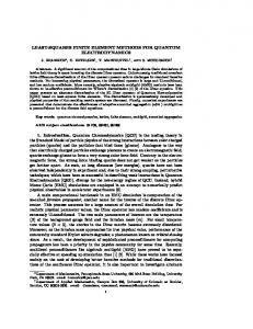
We demonstrate Aharonov-Bohm effect by simulating an electron dynamics on a system as illustrated in Fig. 9.
Wall L D
x d
W
Wall with a magnetic flux Space with a vector potential Free space
y=l
I(x)
L
y
L
FIG. 9. The model system for the Aharonov-Bohm effect. The shape of this system is rectangular. A double-slit lies at the center. A magnetic flux Φ goes through a wall lying between the slits. 64 × 128 computational grid points are allocated in the physical size 8a.u. × 16a.u. The initial wavefunction is set as a plane wave k in front of the double-slit. The time slice is set as ∆t = 1/64a.u.
-400
-200
0 x
200
400
FIG. 10. The interference pattern observed in the back of the double-slit and at the line y = ℓ = L/4 in a case of no magnetic flux, Φ = 0. The solid line indicates the numerical result; the dashed line indicates the semi-classical one derived from eq. (44).
The vector potential is constructed as follows: Z x A(x, y) = (0, Ay (x), 0)T ; Ay (x) = − dx′ B(x′ , y) .
Further, the results for the case of magnetic flux Φ = h/2e and Φ = h/e are shown in Figs. 11 and 12, respectively. The patterns are observed to shift to the right-hand side, and these behaviors also agree with the semi-classical one. However, the patterns are different from the the semi-classical one in their details. This is of course due to the quantum effect.
−L/2
(42) Thus Ay (x) has a finite value only inside the right slit: � −B(D − d) : inside the upper slit. Ay (x) = , (43) 0 : in other area. 6
IV. CONCLUSION
I(x)
We have improved the computational method for the time-dependent Schr¨odinger equation by utilizing the finite element method and by formulating a new scheme for a magnetic field. We have found that by using the FEM, the accuracy of the simulation is dramatically improved without any increase in the computational cost. We have also found that the new scheme is quite efficient for simulating systems in a magnetic field. This computational method is especially useful for simulating dynamics of electrons in a variety of meso-scopic structures.
-400
-200
0 x
200
[1] R. Varga, Matrix Iterative Analysis (Prentice-Hall, Englewood Cliffs, NJ, 1962), p.273. [2] H. De Raedt and K. Michielsen, Computers in Physics, 8, 600 (1994). [3] T. Iitaka: Phys. Rev. E 49 (1994) 4684. [4] H. Natori and T Munehisa: J. Phys. Soc. Japan 66 (1997) 351. [5] O. Sugino and Y. Miyamoto: Phys. Rev. B 59 (1999) 2579. [6] W. H. Press, S. A. Teukolsky, W. T. Vetterling and B. P. Flannery: Numerical Recipes in C (Cambridge University Press, 1996) chapter 19, section 2. [7] H. De Raedt and K. Michielsen: Phys. Rev. B. 50 (1994) 631 [8] T. Iitaka, S. Nomura, H. Hirayama, X. Zhao, Y. Aoyagi and T. Sugano: Phys. Rev. E 56 (1997) 1222. [9] H. Kono, A. Kita, Y. Ohtsuki and Y. Fujimura: J. Comput. Phys. (USA), 130 (1997) 148. [10] E. Tsuchida and M. Tsukada: J. Phys. Soc. Japan 67 (1998) 3844. [11] N. Watanabe and M. Tsukada: Phys. Rev. E 62 No.2 (2000) in press. [12] M. Suzuki: Phys. Lett. A 146 (1990) 319. [13] M. Suzuki: J. Math. Phys. 32 (1991) 400. [14] K. Umeno and M. Suzuki: Phys. Lett. A 181 (1993) 387. [15] M. Suzuki: Proc. Japan Acad. 69 Ser. B, 161 (1993). [16] M. Suzuki and K. Umeno: Springer Proceeding in Physics 76 (1993) 74. [17] M. Suzuki: Phys. Lett. A 201 (1995) 425.
400
I(x)
FIG. 11. The interference pattern observed in the back of the double-slit and at the line y = ℓ = L/4 in a case of Φ = h/2e. The solid line indicates the numerical result; the dashed line indicates the semi-classical one derived from eq. (44).
-400
-200
0 x
200
400
FIG. 12. The interference pattern observed in the back of the double-slit and at the line y = ℓ = L/4 in a case of Φ = h/e. The solid line indicates the numerical result; the dashed line indicates the semi-classical one derived from eq. (44).
7