Finite Element Design Study of a Bladed, Flat Rotating Disk to Simulate Cracking in a Typical Turbine Disk Ali Abdul-Aziz 1 , Jeffrey J. Trudell 2 and George Y. Baakilini 3 NASA Glenn Research Center Cleveland, Ohio 44135 ABSTRACT Developing health management and ultrasafe engine technologies are the primary goals of NASA’s Aviation Safety Program. Besides improving safety, health monitoring can also reduce maintenance costs. A unique disk spin simulation system was assembled by the Nondestructive Evaluation (NDE) Group at NASA Glenn Research Center to verify and study a crack detection technique based upon observing center of mass changes of the rotor system using various sensing technologies. This paper describes the finite element analysis results of low cost, a 25.4 cm (10 in.) diameter, flat turbine disk used to evaluate the detection techniques by simulating typical cracks observed in turbine engine disks. Changes in radial tip displacement and center of mass are presented as a function of speed, crack size and location. Keywords: health monitoring, finite element, Crack initiation, flat disk, NDE, Aviation Safety, Center of mass, rotor damage, unbalances.
1. INTRODUCTION Health monitoring of rotating components in aircraft engines continues to generate strong interest among the engine companies and government institutions to improve safety and to lower maintenance costs. In general, a health monitoring system requires that: 1) the sensor system be capable of sustaining normal function in a severe environment; 2) to transmit a signal if a detected crack in the component is above a predetermined length, but below a critical length that would lead to failure; and 3) to act neutrally upon the overall performance of the engine system and not interfere with engine maintenance operations. Currently, NDE techniques are used to perform periodic inspections and major overhauls to discover any cracks that may have formed to prevent catastrophic failure (burst) of the engine. The lowest cost NDE technique is Fluorescent Penetrant Inspection (FPI). However, FPI often fails to disclose cracks that are tightly closed during rest or that are below the surface. The NDE eddy current system is more effective at detecting both crack types, but requires careful setup and operation, while allowing only a small portion of the disk to be practically inspected. Therefore, the need for more reliable diagnostic tools and high level techniques for damage detection and health monitoring of rotating components are essential elements in maintaining engine safety, reliability and life assessment. The above concerns are high priorities of the NASA Aviation Safety Program (AvSP), which intends to develop and demonstrate technologies that will contribute to a reduction in the aviation fatal accident rate by a factor of 5 by 2007. This ambitious program is a partnership that includes NASA, the Federal Aviation Administration (FAA), the aviation industry and the Department of Defense [1]. The program’s objectives are to: (1) develop and demonstrate technologies that reduce aircraft accident rates; and (2) develop technologies that reduce aviation injuries and fatalities when accidents do occur. In support of the latter aim, the NDE Group at NASA Glenn Research Center at Lewis Field is actively involved in developing combined experimental-analytical capabilities to address the development of specific health monitoring technologies to detect rotor damage prior to any catastrophic events [2]. The developed system allows for precision controlled spin tests that can facilitate the application of various sensing technologies for in situ detection 1
Senior Research Scientist, Cleveland State University, Dep. of Civil and Env. Engineering, NASA Glenn Research Center, 21000 Brookpark Road MS 6-1, Cleveland, Ohio 44135, Phone (216) 433-6729, Fax (216) 977-7150, Email:
[email protected]. 2 Senior Aerospace Engineer, Structural Mechanics and Dynamics Branch, NASA Glenn Research Center, 21000 Brook Park Rd. MS 49-8, Cleveland, Ohio 44135, Phone (216) 433-5303, Fax (216) 977-7051, Email:
[email protected]. 3 Supervisory Electronics Engineer, Optical Instrumentation Technology Branch, NASA Glenn Research Center, 21000 Brookpark Road MS 77-1, Cleveland, Ohio 44135, Phone (216) 433-6016, Fax (216) 977-7150, Email:
[email protected].
of rotor damage. System capabilities include performing systematic evaluations of crack detection techniques through the implementation of highly controlled crack initiation and growth tests on subscale spinning rotors up to 46 cm (18 in.) and 10 000 rpm. In addition, the system has elevated temperature capabilities up to 540 °C (1000°F). The topic of crack detection technique has been studied by many researchers [3-4] where vibration response of a cracked rotor passing through the critical speed is examined utilizing a simple hinge model for small cracks. Bently [5] presented a rotor crack detection procedure based on the start-up and shutdown vibration monitoring. Additional relevant data concerning the state-of-the-art vibration methodologies related to cracked structures can be found in reference[6]. This paper presents finite element results of an existing, low cost, 25.4 cm (10 in.) diameter flat turbine-like disk test article that simulates cracks of varying sizes in turbine disks and hence experimentally evaluate various crack detection techniques by simulating cracks in turbine disks. The results are focused on finding the changes in maximum radial deflections and changes in the center of mass as a function of rotational speed and crack characteristics (crack size and location) to make detection feasible in the subscale flat test article. The motivation of the study is that cracks as small as 1.27 mm (0.05 in) have been detected in jet engine rotors tested in spin pits [7] by monitoring radial vibration amplitude and phase and by detecting changes in the center of mass associated with a minute unbalance of the distorted strain field of a developing crack [8].
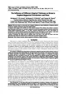
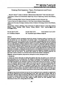
2. PROBLEM DESCRIPTION AND APPROACH The conceptual design for this study utilized flat 25.4 cm (10 in.) disks with machined teeth to imitate compressor or turbine blades to provide a cost effective test article to simulate crack initiation and propagation. The central region of the flat disk is counter-bored on both sides to create the rim, web, and bore regions of a typical turbine disk. The machined teeth on the rim simulate blade tip passing, but reduce the effective blade mass-loading on the web and bore of typical blades. The goal of this design study is to induce changes in radial tip displacement of 1.97 μm (0.0005 in) without disk yielding in order to test the instrumentation, and to then initiate and grow cracks by machining and/or increased rotational speed. The flat disk considered in theses analyses is shown in Figure 1. In previous work, cracks introduced into this geometry at holes near the rim generated changes in radial displacements that were very small and experimentally unmeasurable [2]. Consequently, a new disk shown in Figure 2 was designed resembling a turbine disk [2], but with increased manufacturing cost. This research re-examines the original flat disk geometry by adding notches through the web thickness and varying the notch location and size in order to induce detectable changes in displacement and center of mass shift to allow the study of crack initiation and growth with advanced health monitoring systems using a cost effective test article. The flat disk geometry is shown in Figure 3, where the outside diameter of the flat disk is 25.4 cm (10 in.); the bore and outside rim thickness is 0.953 cm (0.375 In.); the thickness of the web is 0.318 cm (0.125 in), and the cross section and height of the blades are 0.318 cm x 0.953 cm (0.125 in x 0.375 in) and 1.27 cm (0.50 In.), respectively. The flat disk has 30 blades evenly spaced around the circumference. Four holes, 0.635 cm (0.25 in.) diameter each, were drilled through the disk at a radius of 10.2 cm (4 in). The holes were spaced every 90°. The holes can be used for mass attachments or locations to machine cracks or notches. The disk considered is made of Nickel CM-400 and the material properties are listed in table 1. Table 1. Nickel CM-400 Material Properties Elastic modulus Poisson's ratio Shear modulus Mass density Tensile strength Yield strength Thermal expansion coefficient Thermal conductivity Specific heat
26 Msi 0.31 9.924 Msi 0.319 lb/in3 70 Ksi 28 Ksi 9.444 E-6 in / (in-ºF) 0.00057529 BTU/(in-s-ft) 0.10989 Btu/(lb-ºF)
2
(179.264 Mpa) 0.31 (1.0 Mpa) (8.829g/Cm3) (482.62 Mpa) (193.05 Mpa) (4.317710-5 cm/°C) (3.5844 W/m.K) (0.460087 J/g°C)
3. FINITE ELEMENT MODELING The rotating flat disk has been modeled and analyzed using the ANSYS finite element program [9]. An input file using the ANSYS Parametric Design Language (ADPL) was created to parametrically build, mesh, solve, and perform data recovery of the flat disk with notches and holes of various sizes and locations. This methodology allows numerous cases to be studied with minimal hands on model development and data recovery within the Graphical User Interface realizing substantial reduction of man-hours. A typical Finite Element model (FEM) with four holes and no notches consists of 75,000 nodes and 55,000 eight noded hex elements as shown in Figure 4(a). The disk centroid was calculated by creating an ANSYS macro. The macro retrieves each element’s centroid and mass and sums the mass and centroid-mass product to calculate the disk centroid. Each element centroid was calculated in global Cartesian coordinates using the ANSYS element centroid command which is based upon the shape function. Displacement results were added to the initial nodal coordinates to determine the disk centroid under centrifugal loading. The ANSYS disk centroid macro was verified by comparing the element and volume centroids of a simple flat cylinder while varying the density and modulus of one quarter of the disk. The macro accuracy is very sensitive to mesh density and mesh symmetry, , and often required mesh refinement as notch lengths and locations were varied The length of the through-the-thickness notch added to the holes in the rim or web was varied between 0.51 to 5.1 cm (0.2 in to 2.0 in). The notch width was usually set to 30.48 μm (0.012 in). The through-the-thickness notch was cut into the geometry of the FEA model, and then meshed. The global mesh size was varied to achieve a difference in the element to volume center of mass calculation of 0.508 μm (0.00002 in) or lower at zero speed for an unnotched disk. Both global and smart size parameters were varied to ensure that numerical stress concentrations did not occur and that similar results were obtained between the solutions of varying mesh size. An unnotched disk analysis required more than two hours of CPU time on a Silicon Graphics work station, more than 500 Mb of core memory, and disk storage of 1GB. Notched disks exceeded 1 GB of core and 8 GB of disk storage with full data recovery. The model was constrained to replicate the disk attachment to the rotating shaft as represented by the experimental setup [1]. A local cylindrical coordinate system was created at the center of disk. All the nodes at the inner radius were constrained in the θ-direction and the axially centered nodes along the inner radius ring were constrained in the axial zdirection. The calculations were made under linear elastic conditions where the behavior of the material is defined by two material constants, Young’s modulus and Poisson’s ratio.
4. RESULTS AND ANALYSIS The hole and the notch were positioned in the rim and the web regions of the disk. The notch length was varied and results for each of these locations are presented in the following sections. 4.1 Notch in Rim Region of Disk A representative notch and hole in the rim region of the disk is shown in Figure 4(b) and is presented to compare to the case when the notch is located in the web region of the disk. Figure 5 shows the von Mises stress of a notch of length 3.302 cm (1.3 in) at 10 000 rpm. The 65.4 Ksi (451 Mpa) stress is significantly above the yield stress of 28 Ksi (193 Mpa). The effects of notch size on net radial displacement in blade tip deflection (maximum minus minimum blade displacement) versus speed is shown in Figure 6 where only a 5.1x10⁻⁴-7.62x10⁻⁴cm (0.0002-0.0003 in.) net displacement is predicted, a significant challenge for a crack detection system. For instance, the yield line was created in Figure 6 by selecting a notch length, varying the speed until the yield stress was reached, and then extracting the net radial tip displacement. Figure 7 indicates that for notch lengths below 4.572 cm (1.8 in) the yield stress is not exceeded below 6,000 rpm. . The change in unbalance is shown in Figure 8 as a function of notch size for various rotational speeds and yield curve is also shown to indicate critical cutoffs conditions. Figure 9 provides data on the actual center of mass location to help perform disk balancing. Tabular results for various notch lengths at the yield stress are summarized in Table 2. Although not presented, varying the initial hole/blade angular alignment has little effect on the results. Figures 10, 11 show the net radial center of mass shift and the maximum radial blade tip displacement as a function of notch length for different rotational speeds. It is noted in Figure 10 that the center of mass shift tends to increase with higher speed and larger notch length as projected.
3
Table 2. Summary of Results of Rim Notch length versus Yield Stress Notch Length (in)
0.7 1.778 cm 1.2 3.048 cm 1.8 4.572 cm
Speed when 28 Ksi Yield Stress Exceeded (Krpm) 10 10 6
(Max-Min) Radial Blade Tip Disp. (In), (cm)
Max. Radial Disp. (In) (cm)
Change in Unbalance (Oz-In) (Oz-Cm)
0.00014 (3.556 x10⁻⁴ ) 0.00024 -4 (6.096 x10 ) 0.00031 -4 (7.874 x10 )
0.00011 (2.794 x10⁻⁴ ) 0.00081 (2.057 x10⁻³ ) 0.00063 (1.600 x10⁻³ )
-0.00011 (2.794 x10⁻⁴ ) -0.00085 (2.159x10⁻⁴ ) -0.00001 (2.54 x10⁻⁵ )
A representative yield curve is also shown which indicates that the cross regions where yielding is likely to occur if the range is exceeded. Figure 11 displays a similar behavior for the maximum radial tip displacement, where higher speeds and larger notches result in larger displacements. A yield curve is also integrated in the data. For instance, no yield is anticipated if the notch is less than 1.7 inches and the speed is not higher that 6000 rpm (Figure 11). 4.2 Notch in Lower Web Region of the Disk The von Mises stress distribution around the notch of length 2.54 cm (1.0 inch) in the web is shown in Figure 12. The peak von Mises stress is 88 Ksi (607 Mpa) at 8000 rpm. The von Mises stress as a function of notch length is shown in Figure 13 and shows that for notch lengths below 3.81 cm (1.5 in), no yielding would occur up to a maximum speed of 4000 rpm. The net radial blade tip displacement versus notch length is shown in Figure 14 and shows that 9.144 x10⁻⁴ cm (0.00036 in.) of net radial tip displacement is possible without exceeding the yield stress. The small change in net tip displacement is due to the small amount of mass loading of the blade and rim region above the notch. The center of mass shift for the notch in the web for various lengths is shown in Figure 15. The change in the center of mass is very small, -2.11 x10⁻⁴ cm (-8.3x10⁻⁵ ) in at 10,000 rpm for a notch size of 3.81 cm (1.5 in). The magnitude of the unbalance shift shown in Figure 16 increases as the notch size and speed increases, with yield occurring at a notch length size of greater than 3.81 cm (1.5 in.), at a speed over 6000 rpm. The maximum radial blade tip displacement is shown in figure 17 and this is useful in determining sensor placement. Additional data are summarized in table 3. Table 3. Summary of Results of web Notch length versus Yield Stress Notch Length (in)
Speed when 28 Ksi Yield Stress Exceeded (Krpm)
1.00 2.54 cm 1.50 3.81 cm 1.75 4.445 cm 2.00 5.08 cm
10 6 4 4
(Max-Min) Radial Blade Tip Disp. (In) 0.00036
(9.14 x10⁻⁴ cm) 0.00025
(6.35 x10⁻⁴ cm) 0.00014
(3.556 x10⁻⁴ cm) 0.00016
(4.064 x10⁻⁴ cm)
Max. Radial Disp. (In) 0.00128
(3.25 x10⁻⁴ cm) 0.00058
(1.47 x10⁻⁴ cm) 0.00028
(7.112 x10⁻⁴ cm) 0.00031
(7.874 x10⁻⁴ cm)
Change in Unbalance (Oz-In) (Oz-Cm) -0.00270
(-6.858 x10⁻³ ) -0.00227
(-5.766 x10⁻³ ) -0.00127
(-3.226x10⁻³ ) -0.00155
(-3.937 x10⁻³ )
Figure 18 shows the effect of increasing the notch width on the von Mises stress versus rotational speed with notch widths of 0.024, 0.036, and 0.060 in (0.061, 0.091, 0.152 cm) for a notch length of 0.50 in (1.27 cm). The data reported in figure indicate that increasing the notch width decreases the stress concentration around the notch tip.
4
5. CONCLUSIONS A parametric study using the finite element method was carried out to investigate the effects of adding notches to a costeffective, flat, turbine-like test article in order to increase displacements that would be detectable for a health monitoring system without exceeding the yield stress. The study methodology incorporated automated FEA parametric design language to substantially reduce man-hours. The effects of notch size and location on radial displacement and centroid shift were investigated for various rotational speeds for a flat disk made out of Nickel base alloy CM-400. The results indicate that adding the notches to the disk will now allow systematic evaluation of crack detection techniques without disk yielding. The web region notch location was shown to be the most critical area in terms of higher stresses and displacements versus having the notch in the rim region and versus that of the two hole configurations. Thus, having a notch in the web region (with adequate rim mass loading) is the ideal location to test the applicability and effectiveness of the damage detecting system by repeatable, simulated crack opening without exceeding yield limits since observable changes in radial tip displacement and mass imbalance are now present. Subsequent changes in the speed or addition of an initiation site will allow highly controlled crack initiation and growth tests on the same spinning disks to examine accuracy and reliability of health monitoring systems and will be the focus of future work
REFERENCES 1. 2. 3. 4. 5. 6. 7. 8. 9.
NASA website; http://www.grc.nasa.gov/WWW/AST/GAP/. Gyekenyesi , A. L. et al; ”Application of Vibration Monitoring Techniques For Damage Detection in Rotating Disks”, Proceedings of the 9th International Symposium on Transport Phenomena and Dynamics of Rotating Machinery, Honolulu, Hawaii, February 10-14, 2002. Sekar, A.S., Prabhu, B.S., Transient Analysis of Cracked Rotor Passing Through Critical Speed, Journal of Sound and Vibration, Vol. 173 (3) (1994), p. 415-421. Sekar, A.S., Prabhu, B.S., Condition Monitoring of Cracked Rotors Through Transient Response, Mechanism and Machine Theory, Vol. 33, Issue 8 (1998), p. 1167-1175. Bentlty, D.E, Detecting Cracked Shafts at Earlier Levels, Orbit Magazine, Bently Nevada, Vol. 3, No. 2, (1982). Wauer, J., On the Dynamics of Cracked Rotors: A literature Survey, Applied Mechanics Review, Vol. 43(1), 1990. PP.13-17. Drumm, M.J., “Nondestructive, Real-Time Measurement of Cracks in Jet Engine Rotors”, www.testdevices.com , 1998. Sonnichsen, H. E., “Real-time Detection of Developing Cracks in Jet Engine Rotors”, www.testdevices.com, 07803-5846-5/00, IEEE, 2000. ANSYS Finite Element Program. ANSYS Release 7.1, ANSYS, Inc., Canonsburg, PA, 2003.
Figure 1. Photo of the flat disk
Figure 2. Photo of Optimized Disk with Increased Rim Mass Loading
5
Figure2. Flat Disk Geometry
Hole/Blade Centers Aligned
a) Mesh Figure 3
b) Geometry
Three dimensional finite element model of the disk a) Mesh with no notches b) Geometry with 2 in., 0.012 in. wide notch located in the rim
6
Nickel CM-400 Blade-Hole Aligned Results
Horizontal Notch
Disk Centroid, Mass, and Shift Calculations
Net Radial Tip Displacement Change, In.
Von Mises Stress at 10000 Rpm
Tip Displacement Due to Notch Length as a Function of To Rotational Speed
0.0012 0.0010
Speed = 2000 Rpm Speed = 4000 Rpm Speed = 6000 Rpm Speed = 8000 Rpm Speed = 10000 Rpm Yield Curve
0.0008 0.0006 0.0004 0.0002 0.0000
0.0
0.2
0.4
0.6
0.8
1.0
1.2
1.4
1.6
1.8
2.0
2.2
Notch Length, In
Figure 6. Net Radial Blade Tip Displacement Versus Notch Length for various speeds with Notch Located in the Rim Region of the disk
Figure 4 Effects of Notch Size on Von Mises Stress at Speeds with Notch in the Rim region of the Disk.
Figure 7. Effects of notch Size on Von Mises Stress at Various Speeds with Notch in the Rim region of the Disk.
7
Figure 8. Effects of notch Size on Unbalance Shift at Various Speeds with Notch in the Rim region of the Disk.
Figure 10. Radial Center of Mass Shift versus Notch length at Various Rotation of notch Size on Von Mises Stress at Various Speeds with Notch in the Rim region of the Disk.
Figure 9. Center of Mass as a function of notch length at Zero and 10,000 Rpm speeds with notch in the Rim Region of the
Max. Stress
Figure 11. Maximum Radial Blade Tip Displacement as a function of Notch Length with Notch in The Rim region of the disk.
8
Figure 12. Center of Mass as a function of notch length at Zero and 10,000 Rpm speeds with notch in the Rim Region of the Disk.
Figure 14. Net radial displacement as a function of notch length with notch in the web region of the disk for various rotational in speeds.
Figure 13.von Mises stress versus notch length with notch the web region for various rotational speeds.
Figure 15. Radial center of mass as a function of notch length with notch in the web region of the disk for various rotational speeds..
Figure 16. Effect of Notch size on unbalance shift at various speeds with notch in the web region of the disk.
9
0.0016 0.0014
Speed= 2000 Rpm Speed= 4000 Rpm Speed= 6000 Rpm Speed= 8000 Rpm Speed= 10000 Rpm Yield
100
One Hole- Web Region
Von Mises Stress, Ksi
Maximum Radial Blade Tip Displacement, In.
0.0018
0.0012 0.0010 0.0008 0.0006 0.0004 0.0002
60 Notch Width =0.024 In Notch Width = 0.036 In Notch Width = 0.060 In
40
20
0.0000 0.4
Notch Width Effects
80
0.6
0.8
1.0
1.2
1.4
1.6
0
Notch Length, In.
0
2
4
6
8
10
Rotational Speed, Krpm
Figure 17. Maximum radial blade tip displacement as a function of notch length with notch in the web region of the disk.
Figure 18. Von misses stress as a function of rotational speed for various notch widths with notch in the web region of the disk
10
12