physical damages to the cells. Practical flash memory often employs a wear- leveling mechanism which contributes to extend the lifespan of flash memory by.
Flash Code with Dual Modes of Encoding Michael Joseph Tan1 , Proceso Fernandez2 , Nino A. Salazar2 , Jayzon Ty2 , and Yuichi Kaji1 1
Graduate School of Information Science Nara Institute of Science and Technology, 8916–5 Takayama, Ikoma, Nara, 630–0192 Japan {joseph-t,kaji}@is.naist.jp http://http://www.naist.jp/en/ 2 Department of Information Systems and Computer Science Ateneo de Manila University, Loyola Heights, Quezon City, 1108 Philippines {pfernandez}@ateneo.edu,{oh_ninja_nas,jayzonkid_21}@yahoo.com http://http://www.admu.edu.ph
Abstract. This paper proposes a novel coding scheme which can extend the lifespan of flash memory. Flash memory has a number of advantages against conventional storage devices, but it must be noted that flash cells which constitute a flash memory accommodate, not a small, but limited number of operations only. A flash code provides a clever way to represent data values in flash memory so that the number of operations over flash cells become as small as possible, which contributes to extend the lifespan of flash memory. Several flash codes have been studied so far, and this paper proposes a novel coding scheme which makes use of two di↵erent modes of encoding. Computer simulation shows that the proposed coding scheme shows much better average-case performance than existing codes. Besides the computer simulation, the paper also gives detailed analysis of the performance which justifies the advantage of the proposed code from a more theoretical viewpoint. Keywords: flash memory, flash code, binary-indexed, dual-mode encoding
1
Introduction
Flash memory is a non-volatile memory that consists of an array of floating-gate cells which are grouped in uniform sized blocks. Each cell can store at most q 1 levels of electric charge which is represented as an integer value. A peculiar characteristic of a flash memory is the asymmetric relationship between the two operations over the cell values. It is simple to raise the level of one cell, but due to physical constraints, reversing the procedure is not allowed. The only way to lower a cell level is through a block erasure which completely removes the charges, bringing the cell level to zero, in an entire erase block of flash memory cells. The continuous use of a block erasure is not favorable because it is slow and inflicts
2
Flash Code with Dual Modes of Encoding
physical damages to the cells. Practical flash memory often employs a wearleveling mechanism which contributes to extend the lifespan of flash memory by equalizing the damages of cells evenly. Despite these e↵orts, the limited lifespan is still a significant issue of flash memory. One option to extend the lifespan of a flash memory is to improve the coding scheme that updates and interprets the data stored in a flash memory. Such coding scheme is called flash code and it is the target of this study. Flash codes can be considered as a generalization of coding scheme for write-once memories and this coding scheme have been studied since 1980s [1][7]. The framework for flash code itself was only introduced in 2007 [3]. In this framework, we consider to store a k-bit data in an erase block which consists of n flash cells, and the performance of a flash code is evaluated in terms of a write deficiency which can be regarded as a quantitative measure of the overhead of the code. For small n and k, Jiang et al. proposed good flash codes which give more number of operations (and hence less write deficiency) than naive simple coding scheme[3]. In [4], investigations are made to enlarge the parameters n and k. Mahdavifar et al. improved the idea of [4], and proposed the index-less indexed flash code (ILIFC)[6]. In ILIFC, cells in an erase block are grouped into smaller sub-blocks which we call slices. Each bit of the k-bit data is assigned with one slice, and the slice is used to remember the current value of the corresponding bit. ILIFC is a simple and powerful coding scheme, but the problem with ILIFC is that the size of a slice must be k or more. This restriction degrades the flexibility of the code construction, and furthermore, a↵ects the performance of the code in a direct manner. There are two area of discussions with regard to the performance of flash code. In papers such as [3, 4, 6], they discuss on lowering the worst-case write deficiency of flash codes. Other papers such as [2, 5] discuss the importance of constructing flash code that has a low write deficiency in the average-case scenario. Both scenarios are equally important. The worst-case scenario depicts the durability of the flash code. On the other hand, the average-case scenario shows the practicality of a flash code which should also be considered since flash memory are intended to be mass produced and be used by people in their daily lives. Based on the above described observations, the authors have proposed several flash codes which can be regard as improvements of ILIFC [8, 9]. Those codes surely show smaller write deficiency than ILIFC, but the use of slices in constructing flash codes seems to bring a certain overhead. To mitigate the issue of using slices, we propose in this paper a new approach in constructing flash code by integrating two modes of encoding. Each mode of encoding is a flash code on its own, but by integrating them we are able to capitalize on their advantages and mitigate their disadvantages. The proposed code shows a much smaller write deficiency than existing flash codes in terms of average-case discussion, and allows accommodating a large data in one fixed size block.
Flash Code with Dual Modes of Encoding
2
3
Preliminaries
A block in a flash memory consists of some fixed number n of cells, and this can be represented by a vector C = (c0 , c1 , . . . , cn 1 ) 2 Anq with Aq = {0, . . . , q 1}. Each element ci of C indicates the amount of charge of the corresponding cell. A cell with a charge 0 is said to be empty while a cell with a charge q 1 is said to be full. A cell that is neither empty nor full is said to be active. This concept is extended to groups of cells which are analogously classified as empty (if it is (0, . . . , 0)), full (if it is (q 1, . . . , q 1)) or active (neither empty nor full). For two states C = (c0 , . . . , cn 1 ) and C 0 = (c00 , . . . , c0n 1 ), we write C C 0 if ci c0i for 0 i < n and C C 0 if C C 0 and C 6= C 0 . A state can transit from C to C 0 only if C C 0 . The information stored in a single block is a k-bit data D = (d0 , d1 , . . . , dk 1 ), where di 2 {0, 1} and k n. The value of the data is updated through a write operation which inverts the binary value of a single bit in the data D. A flash code F bridges together the physical state of a block with the logical interpretation of the data that the block contains. Formally, a flash code consists of a pair of functions F = (E, D). The encoding function E : {0, 1, . . . , k 1}⇥Anq ! Anq [{E} is invoked at each write operation, and E(j, C) provides the rules on how to write a new state (possibly a block erasure E) to the block given the index j of the data bit dj to be changed and the current state C 2 Anq of the block. The decoding function D : Anq ! {0, 1}k interprets the contents of the block into the corresponding k-bit data value. Furthermore, if E(j, C) = C 0 where C 0 6= E and j is the index of the bit given by a write operation, then value of D(C) and D(C 0 ) are the same except for j-th bit position. A flash code increases at least one cell level for each write operation, and therefore, the maximum number of write operations allowed for a block is n(q 1).This value is used to define a metric for flash codes, called the write deficiency: (F ) = n(q
1)
t
(1)
where t is the number of write operations that the flash code F is able to accommodate before a block erasure. Flash codes are usually compared against one another in both the average-case and worst-case performances using the write deficiency metric, and a smaller value of (F ) is more favorable. To normalize this metric, we further divide the write deficiency by n(q 1), to produce the write deficiency percentage which we use for the average case performance analysis in later sections. Among several constructions of flash codes, the authors are especially interested in those suitable for large parameters of n and k. In this aspect, the index-less indexed flash code (ILIFC)[6] seems promising because it is simple and scalable in nature. The key idea of ILIFC is, the authors consider, the use of slices which is a small group of flash cells. Through clever encoding rule, a slice is able to store both of the index and the value of a bit of the data. This mechanism assigns more number of cells to more frequently written bits, and
4
Flash Code with Dual Modes of Encoding
contributes to reduce the write deficiency. The problem with ILIFC is that the p size of a slice is fixed to k, which requires that k n and some degradation of write deficiency. To overcome this problem, the authors have studied encoding techniques such as the binary-indexed slice encoding and its e↵ective uses[8][9]. The flash code which is discussed in the following sections can be regarded as the extension of those studies of the authors.
3
Dual-Mode Flash Code
In this study, we propose a new flash code which we refer to as dual-mode flash code (DMFC). This flash code incorporates two modes of encoding; stacked segment encoding (SS encoding) and binary-indexed slice encoding (BS encoding)[9]. SS encoding works fine if all data bits experience almost the same numbers of write operations, but its efficiency is degraded if some data bits are written more frequently than others. To get around this problem of SS encoding, we consider to temporally switch to BS encoding, and accommodate excess write operations for those frequently written bits. The use of BS encoding brings a certain overhead, but the BS encoding is able to incorporate the “non-uniform” situation in which some bits are written more frequently than others. In the following, we first introduce the two encoding schemes which are used in the proposed flash code. 3.1
Stacked Segment Encoding
A simple encoding rule, which we call stacked segment encoding (SS encoding), is introduced in this section. A segment is a group of k cells in an erase block, and a stack of segments is an ordered collection of segments. Let h be the number of segments contained in a stack, and let Si = (ci,1 , . . . , ci,k 1 ) with 0 i h 1 denote the i-th segment in the stack. In this encoding, the value ci,j is managed in such a way that ci,j is not empty only if all of c0,j , . . . , ci 1,j are full. In a sense, h cells c0,j , . . . , ch 1,j are stacked over, and used from the bottom of the stack. Those h cells form a single virtual cell whose value can be h(q 1) at the maximum, and represents the value dj of the j-th bit of the data by Ph 1 dj = ( i=0 ci,j ) mod 2. The encoding operation is obvious; to flip the value of dj , we determine the smallest integer i such that ci,j is not full, and increase the value of ci,j by one. If all of c0,j , . . . , ch 1,j are full, then we allocate a new segment, push that new segment on the top of the existing stack, and raise the value of ch,j in the newly stacked segment. A block erasure is called if we cannot allocate a new segment in the erase block. This SS encoding works fine if all data bits experience almost the same number of write operations. However, we need to retain many active segments, which results in large write deficiency, if there is big di↵erence among the numbers of write operations for data bits. To mitigate this issue, we include another mechanism for recording excess write operations, and invoke that mechanism if we already have too many active segments. To implement a trigger mechanism for
Flash Code with Dual Modes of Encoding
5
that switch, a slightly modified encoding function is defined and denoted by ES,m with m an integer parameter. The function ES,m works almost the same way as the above explanation, but ES,m refuses to allocate a new segment and issues a failure signal if the stack already has m active segments. We use DS,m to denote the decoding function of this encoding. 3.2
Binary-Indexed Slice Encoding
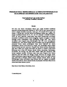
The binary-indexed slice encoding (BS encoding) is an encoding scheme which is similar to (the first-phase of) ILIFC but makes use of smaller slices than ILIFC. A slice is a set of s cells where s = k in ILIFC, and s is the smallest even integer which satisfies s blog2 (k + 1)c + 1 in this BS encoding. An active slice S = (c0 , . . . , cs 1 ) represents a bit index i(S) and a bit value v(S) by itself. The value dj of the data is regarded as one if and only if the erase block contains an active slice S with i(S) = j and v(S) mod 2 = 1. In the BS encoding, slices are operated through the “binary-indexing” rule which is reviewed in this section. See [9] for more detailed explanation of the rule. We also assume that readers are familiar with the principle of the index-less indexed encoding in [6]. The binary-indexing encoding rule consists of four phases. The phase-1 rule is used only when an empty slice S = (c0 , . . . , cs 1 ) is “activated”, that is, the slice is assigned an index j. In this phase, cell values are set so that (c0 · · · cs 1 )2 becomes the binary representation of j + 1 (i.e., j + 1 = c0 2s 1 + · · · + cs 1 20 ). Cells having the value of 1 after this operation are called type-1 cells, and cells having the value of 0 are called type-0 cells. Note that a slice contains both of type-0 and type-1 cells because 1 j +1 k, and therefore the Hamming weight of (c0 · · · cs 1 )2 is more than 0 and less than s. Further encoding operations are defined so that type-0 cells and type-1 cells are always distinguishable, and we can find that i(S) = j by identifying the types of cells. The phase-2 rule is applied as far as we have a type-1 cell which is not full. In this phase, the encoding function selects a type-1 cell that has the lowest value among all type-1 cells, and raise the value of the selected type-1 cell by one. The types of cells are distinguishable because all type-0 cells are empty while all type-1 cells are not. The phase-3 rule is applied if the criteria of the phase-2 does not hold and there is at least one type-0 cell whose value is less than q 2. The rule in this phase-3 is similar to that of the phase-2, but the encoding function selects a type-0 cell that has the lowest value, and raise the value of the selected type-0 cell by one. Note that the cell cannot be full because the value of the selected type-0 cell was less than q 2. Therefore, all type-0 cells remain not full, while all type-1 cells are full. The final phase-4 rule is used if the values of cells in the slice are either of q 2 (for the type-0 cells) or q 1 (for the type-1 cells). In this phase, all cells are filled up and the slice is brought to full. Figure 1 illustrates the change of the state for the case of s = 4, q = 4 and j = 4. In this case, j + 1 = 5 = (0101)2 and the second and the fourth cells are type-1. Type-1 cells are operated in the phase-2, and type-0 cells are operated
6
Flash Code with Dual Modes of Encoding
0 0 0 0 0 1 0 1 phase-1
0 2 0 1
0 2 0 2 0 3 0 2 phase-2
0 3 0 3
1 3 0 3
1 3 1 3 2 3 1 3 phase-3
2 3 2 3
3 3 3 3 phase-4
Fig. 1. The operation of cell values in binary-indexing rule
in the phase-3. Remark that type-0 cells are never filled-up in the phase-3, and the type of cells in an active slice are always distinguishable. The bit value v(S) is defined as the Psnumber of operations that the slice has experienced so far, that is, v(S) = ( i=0 ci wj + 1) mod 2, where wj is the Hamming weight of the binary representation of i(S)+1. We denote the encoding and decoding functions of BS encoding by EB and DB , respectively. 3.3
Dual-Mode Flash Code
To accommodate both of the SS encoding and BS encoding in one erase block (c0 , . . . , cn 1 ), we consider to allocate segments of SS encoding from the beginning of the erase block, and slices of BS encoding from the end of the erase block. The allocation is done in an adaptive manner. If ES,m requests the i-th segment, then the segment is allocated at (cik , . . . , c(i+1)k 1 ). If EB requests the i-th slice, then the slice is allocated at (cn 1 (i+1)s+1 , . . . , cn 1 is ). In both cases, the allocation fails if the erase block does not contain enough number of empty cells. To prevent possible collision of the allocation of segments and slices, we consider to keep s or more cells empty between the region of segments and the region of slices. By scanning slices from the end of the block, we can precisely identify the region of slices. The region of segments are then easily identified because the two regions cannot overlap. The encoding function E of the dual-mode flash code (DMFC) is described by utilizing the encoding functions ES,m and EB . Given a bit index j and a current state C, E(j, C) first invokes ES,m (j, C) and tries to record the write operation by the SS encoding. If ES,m (j, C) successfully records the change, the encoding completes. If, unfortunately, ES,m (j, C) issues the failure signal, then E(j, C) invokes EB (j, C) and tries to record the write operation by BS encoding. In case EB (j, C) cannot accommodate the write operation, E(j, C) returns E and requests a block erasure. The decoding function D is simply defined as D(C) = (DS,m (C) + DB (C)) mod 2.
3 2 1 0
segment 5 3 4 1
0 9 6 2
c0 c1 c2 c3 c4
segment 1 10 15 8 13 7 11 c5 c6 c7 c8 c9
slice 1 empty cells
slice 0
16
14 17 12 12
c92 c93 c94 c95 c96 c97 c98 c99
Fig. 2. A demonstration of the encoding process of DMFC
Flash Code with Dual Modes of Encoding
7
Figure 2 illustrates how the cell values are raised in the encoding of DMFC. We assume that n = 100, k = 5 and q = 4. In this which means that only two segments can be simultaneously active. Each column in the simultaneously setting, a slice consists of s = 4 cells. We also assume that m = 2 array of boxes corresponds to a cell, and boxes represents the use of cell levels. If 17 write operations are performed on bits 2, 3, 2, 0, 2,
3, 2, 2, 3, 2,
3, 2, 3, 2, 3,
3, 2
in this order, then cell levels are used as illustrated in the figure. Up to the 11th write operation (counting from 1), the writes are recorded in segments by using the SS encoding. The 12th write on the bit 2 is not accommodated by the SS encoding because it requires a third active segment which is not allowed, and we switch to the BS encoding. A slice 0 is allocated, and the third and the fourth cells in the slice become type-1 because 2 + 1 = (0011)2 . Meanwhile, the writes on the bit 2 is accommodated by the BS encoding, but it has the chance to switch back to the SS encoding when more write operations are performed and the segment 0 becomes full.
4
Results and Analysis
4.1
Four Factors of Write Deficiency
The write deficiency of DMFC is contributed by four factors. The first and the second factors are the write deficiencies made by active segments and active slices, which we denote by 1 and 2 , respectively. The third factor 3 of the write deficiency is the contribution made by full slices.3 It is shown in [9] that one full slice contributes s 2 write deficiency. If we can determine the number ✓ of full slices, then 3 = ✓(s 2). The fourth factor 4 is made by cells which do not belong to any segments or slices. Using the number of such cells, we can write 4 = (q 1). 4.2
Worst Case Write Deficiency
Depending on the parameters n, k, q and m, there are two di↵erent scenarios which result in the largest write deficiency. The first scenario is such that write operations are made only on one bit until the block erasure occurs. In this case, the SS encoding accommodates the first m(q 1) write operations, and the other write operations are all made through the BS encoding using binary-indexed slices. At the time of block erasure, we have m active segments which occupy mk cells, no active slice, ✓ = b(n mk)/sc 1 full slices, and = n mk ✓s cells which do not belong to any segments or slices. Each active segment contains one full cell and k 1 empty cells, and 3
Di↵erent from slices, full segments makes no contribution to the write deficiency, and we can ignore full segments in the analysis of write deficiency.
8
Flash Code with Dual Modes of Encoding
therefore one such segment contributes (k 1)(q 1) write deficiency each. We have 1 = m(k 1)(q 1), and the write deficiency in this scenario is given by 1
+
2
+
3
+
4
= m(k
1)(q
1) + 0 + ✓(s
2) + (q
1).
(2)
In the second scenario, m(q 1) + 1 write operations are made to k 1 data bits, and then, write operations are made to the remaining one bit until the block erasure occurs. This pattern of write operations results in m full segments, m active segments, k 1 active slices, ✓ = b(n 2mk (k 1)s)/sc 1 full slices and = n 2mk (k 1 + ✓)s cells which do not belong to any segments or slices. Similar to the previous scenario, each active segment contributes (k 1)(q 1) write deficiency. The active slice is used only once, and each active slice contributes s(q 1) 1 write deficiency. Consequently,
1
+
2
+
3
+
4
= (k
1)((m + s)(q
1)
1) + ✓(s
2) + (q
1).
(3)
There is no particular order between the values of (2) and (3); the former can be larger than the latter for some specific parameters, and the converse is true for some other parameters. In an asymptotic “big-O” notation, however, (3) gives the worse (larger) write deficiency because (2) is in O(qk + n) and (3) is in O(qk log k + n). The write deficiency of DMFC contains O(n) factor, and therefore worse than ILIFC. However, as we see in the next section, DMFC shows remarkably superior write deficiency in the average case. 4.3
Average Case Write Deficiency
Computer simulation was performed in order to estimate the average case write deficiency of DMFC against ILIFC and some other flash codes. It should be noted that ILIFC in its original form [6] consists of two main phases, but we only implemented the first phase of ILIFC since, as observed in [3], the contribution of the second phase is not significant in a non-asymptotic discussion. For the simulations, we fixed the values of n = 2048 and q = 8, and investigated the results at di↵erent values of k. For each k value, 30 experiments were run, and the average write deficiency percentage was gathered. It is assumed that all k data bits have the equal probability to be selected by write operations. Figure 3 shows the average write deficiency percentage of several flash codes including ILIFC and DMFC. DMFC-4 and DMFC-6 stand for DMFC with m = 4 and m = 6, respectively. To understand the contribution of the dual-mode encoding, the graph also shows the performance of “single-mode” flash codes; SSonly (simulated) shows the write deficiency of a flash code that makes use of the SS encoding technique only (the number of active segments is not bounded in this case), and BS-only shows the write deficiency of a flash code that makes use of the BS encoding technique only. We can see that DMFC shows the smallest write deficiency among all flash codes compared. Unlike ILIFC and BS-only encoding, DMFC and SS-only encoding do not have a degeneration point where the write
Flash Code with Dual Modes of Encoding
9
'"#
'
!"&
!"%
!"!#$
%&'()*+
&&'()*+,-./01*23456
78#$'9
78#$':
&&'()*+,-2)2*+3/;2*6
!"$
!"#
! (
#!(
$!(
%!(
&!(
'!!(
'#!(
'$!(
'%!(
'&!(
#!!(
Fig. 3. Write deficiency percentage.
deficiency percentage shoots up close to 1. This favorable characteristic is due to the use of segments which allow us to start encoding by assigning only one cell to each bit. This is not possible in a pure slice-based flash code, and DMFC inherits the advantage of the segment-based encoding. We can also see that DMFC shows better performance than SS-only encoding. This is because DMFC makes use of slices whose size is much smaller than segments. Consider for example that, after several encoding operations, we have k 1 empty cells in an erase block. The space is too small to accommodate a new segment, but sufficient to accommodate several slices. In this sense, DMFC inherits the advantage of the slice-based encoding. The e↵ect of the parameter m is not clear in these experiments. For small values of k, we can see that DMFC-6 shows better performance than DMFC-4. For large values of k, the di↵erence of m makes little sense because, if k is large, then an erase block is able to accommodate a limited number of segments. We have seen that the write deficiency of DMFC is contributed by four factors. Figure 4 shows the contribution of each factor on the write deficiency. The graph shows that the contribution of 3 and 4 are almost negligible. The major factors of write deficiency are 1 and 2 which are made by active segments and active slices, respectively. Figure 4 shows that the value of 2 changes regularly according to the value of k. This phenomenon can be explained in terms of the number of slices. Except for very small values of k, the DMFC tends to allocate as many segments as possible in the erase block. This means that only n mod k cells are used to accommodate slices, and the number of slices is about (n mod k)/s. These slices are once assigned, but not used so much. Almost all
10
Flash Code with Dual Modes of Encoding !"*
!"#$%&
'(
')
'*
!") !"(
'+ !"' !"& !"% !"$ !"# ! '
$!'
&!'
(!'
*!'
#!!'
#$!'
#&!'
#(!'
#*!'
$!!'
Fig. 4. An analysis of the di↵erent factor of write defiency of DMFC
cell levels in the slices are left unused, which implies that 2
=
(s(q
1)
2
is approximated as
1) (n mod k) . s
(4)
Even though this discussion is quite harsh, the formula well explains the experimental result in Fig. 4. For the estimation of 1 , we consider the number of segments which are used in SS-only encoding. Even though DMFC and SS-only encoding are di↵erent, the estimation result on the SS-only encoding helps in analyzing DMFC also. In Section 3.1, we saw that cells in a stack of segments constitute a virtual cell, and we have k virtual cells in a stack of segments. Let Xwt with w 0 and t 0 be a random variable denoting the number of virtual cells whose values are w or more after t write operations. Obviously X00 = k and Xw0 = 0 for w > 0. With one write operation, one of virtual cells is selected and its value is increased by one. If a cell with value w is selected at the t-th write operation, t+1 t t then Xw+1 = Xw+1 + 1. This event occurs with probability of (Xwt Xw+1 )/k, t and therefore the expected values of Xw satisfy t+1 t E[Xw+1 ] = E[Xw+1 ] + (E[Xwt ]
t E[Xw+1 ])/k.
(5)
t If we regard that the h-th segment is allocated when E[X(h 1, then 1)(q 1)+1 ] (5) defines a certain relation between t and h. Figure 5 shows the growth of the number of segments obtained from (5), and that gathered from computer simulations for DMFC-6 and SS-only encoding. We can see that the recursive relation (5) accounts for the number of segments used in DMFC. Let hmax = bn/kc be the maximum number of segments which can be allocated in an erase block, and let tmax be the smallest integer such that E[Xhtmax ] 1. The max (q 1)+1 value of tmax can be regarded as the estimation of the number of write operations accommodated by SS-only encoding. Unfortunately tmax is not derived by a closed-form formula, but we can determine tmax by a computer search. The curve of SS-only (analytical) in Fig. 3 shows the value of tmax for each value of k. The analytical values are slightly larger than the values gather by computer
Flash Code with Dual Modes of Encoding
11
%!
!!"#$%&'($) **+, $"
!!"#$%&'($)-.#/01%21'3
!"#$%&$'(#
$!
#"
#!
"
! #
$!#
&!#
'!#
(!#
#!!#
#$!#
#&!#
#'!#
#(!#
$!!#
$$!#
$&!#
$'!#
Fig. 5. The growth of the number of segments
simulation, but give good approximation of the average write deficiency of SStmax only encoding. Using the value of tmax , vw = E[Xwtmax ] E[Xw+1 ] can be regarded as the expected number of virtual cells whose values are w. A virtual cell with value w contributes m(q 1) w write deficiency, and the value of 1 , which is the write deficiency contributed by active segments, is given as m(q 1) 1 1
= m(q
1)k
m(q
tmax 1)(E[Xm(q 1) ])
X
vw w.
(6)
w=0
Because 3 and 4 are negligible, the average write deficiency is approximated as 1 + 2 , which is computed by using (4) and (6). We have clarified all four factors of the write deficiency of DMFC, though some computer search is needed to determine the value of 1 .
5
Conclusion
In this paper, a new flash code, called dual-mode flash code (DMFC), is proposed. DMFC inherits advantages of the stacked segment encoding and binary-indexed slice encoding, and shows remarkable write deficiency in the average case. The paper also investigates the average write deficiency of DMFC, and proposed an analytical estimation of the write deficiency. Further studies can focus on providing a more rigorous discussion of the average performance, and the derivation of a closed-form formula of the write deficiency. Furthemore this paper introduces a new method for constructing a flash code. Further research can also involve investigating combining di↵erent modes of encoding to create new flash codes.
References 1. Fiat, A., and Shamir, A.: “Generalized Write-Once Memories,” IEEE Trans. Inform. Theory, vol. 430, pp. 470-480, September 1984.
12
Flash Code with Dual Modes of Encoding
2. H. Finucane, Z. Liu and M. Mitzenmacher,“Designing floating codes for expected performance,” Proc. 46-th Allerton Conf. Communication, Control and Computing, pp. 1389-1396, Monticello, IL, September 2008. 3. Jiang, A., Bohossian, V. and Bruck, J.: “Floating codes for joint information storage in write asymmetric memories,” Proc. IEEE Intern. Symposium on Information Theory, pp. 1166-1170, Nice, France, June 2007. 4. Jiang, A. and Bruck, J.: “Joint coding for flash memory storage,” Proc. IEEE Intern. Symposium on Information Theory, pp. 1741-1745, Toronto, Canada, July 2008. 5. Kaji, Y.: “The expected write deficiency of index-Less indexed flash codes,” IEICE Trans. Fundamentals of Electronics, E95-A, December 2012. 6. Mahdavifar, H., Siegel, P.H., Vardy, A., Wolf, J.K. and Yaakobi, E.: “A nearly optimal construction of flash codes,” CoRR, abs0905.1512, 2009. 7. Rivest, R.L. and Shamir, A.: “How to reuse a write-once memory,” Information and Control, vol. 55, pp. 1-19, December 1982. 8. Tan, M.J. and Kaji, Y.: “Uniform-compartment flash code and binary-indexed flash code,” IEICE Technical Report, IT2012-13, pp. 25-30, July 2012. 9. Tan, M.J. and Kaji, Y.: “Flash code utilizing resizable-clusters,” IEEE Intl. Conf. on Electro/Information Technology, May 2013.