ing power than JPEG, but deliver a higher PSNR. Furthermore, the artefacts introduced at low bit rates are more easily tolerated by the viewer. In this paper, we ...
Flexible Embedded Image Communication using Levels of Detail and Regions of Interest Uwe Rauschenbach, Heidrun Schumann University of Rostock, Computer Science Department, D-18051 Rostock, Germany
Keywords
Progressive image transmission has been studied since the 70s (see, e.g., [2, 3, 5, 7, 15]). Often, a rough approximation (preview) of an image is sufficient for the user to decide whether or not it should be transmitted in greater detail. The image can be refined automatically (progressive refinement) or by explicit user request (detail on demand) to a greater degree of detail. In low-bandwidth environments, it is essential that only differential data are transmitted. For image coding, Shapiro introduced the notion of an embedded bitstream, in which „all encodings of the same image at lower bit rates are embedded in the beginning of the bit stream for the target bit rate“ ([13], p. 3445). In imaging and image processing systems, quite often regions of interest (RoIs) are used to constrain time-consuming operations to certain parts of an image, thus speeding them up. Another concept, which is popular in the virtual reality community, are levels of detail (LoDs). Here, an object is stored multiple times at different levels of complexity, or as a progressive mesh. Depending on measures like viewing distance or target frame rate, the representation which gives the best trade-off between quality and rendering speed is selected for rendering. Several image compression methods have been developed since the emergence of multimedia systems. The widely used JPEG standard [10] offers high speed compression/decompression with moderate artefacts at medium bitrates. Wavelets [9] need more computing power than JPEG, but deliver a higher PSNR. Furthermore, the artefacts introduced at low bit rates are more easily tolerated by the viewer.
Embedded image communication, Level of detail, Region of Interest, Raster image, Fish eye view Abstract In this paper, we introduce a formal model which describes consistently levels of detail and regions of interest for the embedded coding and progressive transmission of raster images. This model serves as the foundation of an image communication system which supports the progressive, redundancy-free transmission of multiple, possibly overlapping regions of interest in an image. We propose the rectangular fish eye view, a focus and context display technique for raster images which efficiently uses this transmission method and saves screen real-estate. To further decrease the data transmission requirements of the display technique, we propose a new wavelet decomposition scheme which allows the resolutions in x and y direction to differ by a power of two, and discuss the implications. 1 Introduction and Related Work In multimedia communication systems, images are an important means to communicate information. Especially in mobile environments, the available bandwidth is often a serious limiting factor. That’s why image compression techniques must be combined with efficient transmission methods to reduce the response time of mobile image communication systems.
In this paper, we will present a flexible image transmission method based on the Embedded Zerotree Wavelet method [13]. We extend the concept of an embedded bitstream by incorporating LoDs and RoIs. The flexibility of the method offers to both image author and image viewer control over the degree of detail in which each RoI is transmitted.
Levels of detail, regions of interest and progressive transmission are popular concepts for handling graphical data in resource-limited environments. The contribution of this paper is to provide a consistent view on the problem of levels of detail and regions of interest tailored for the progressive transmission of raster images.
-1-
PSNR [dB] vs. stream size, lena
encoding time [s] vs. stream size, lena
decoding time [s] vs. stream size, lena 1.80
JPEG
1.60
our EZW implementation
1.60
our EZW implementation
1.40
LuRaWave [LWF]
1.40
LuRaWave [LWF]
55176
28259
20418
17602
14690
9796
8008
6516
5445
4196
55176
55176
28259
20418
17602
14690
9796
11330
8008
6516
5445
4196
2955
500
1652
28259
0.00 20418
0.20
0.00
16.00
17602
0.20 14690
0.40
SPIHT [SPe96]
9796
0.40
11330
0.60
LuRaWave [LWF]
8008
21.00
6516
0.80
0.60
5445
0.80
our EZW implementation
4196
JPEG
2955
26.00
500
1.00
1652
1.00
31.00
SPIHT [SPe96]
1.20
2955
SPIHT [SPe96]
1.20
500
36.00
1.80
1652
41.00
2.00 JPEG
11330
2.00
46.00
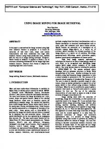
Figure 1: PSNR, encoding and decoding performance comparison (SUN SPARC Ultra-1, 166MHz)
Fourth, we propose the rectangular fish eye view as a new method for raster image viewing, saving both screen real estate and transmission bandwidth based on our RoI/LoD model. Fourth, we describe extensions to the classic wavelet decomposition scheme needed to realise rectangular fish eye views efficiently. Finally, we discuss our results and present directions for future work.
Several authors have studied different aspects of the problem addressed by our work. Zhang [17] has presented a mobile image handling system, which is capable of selecting a wavelet filter depending on the available resources and supports zooming of the image. Chang et al. [1] describe an image transmission system which assigns priority to wavelet coefficients depending on their distance from so-called „foveal points“. Coefficients near a foveal point are transmitted with precedence. The foveal points could be called „points of interest“ similarly to our regions of interest concept. This method requires storing the transmission status for each individual wavelet coefficient rather than only for each region, which is memory-consuming. Furthermore, no compression is used. The Internet Imaging Protocol [6] supports structured access to the FlashPix™ image file format. It is capable of zooming and panning large images, but uses independent (redundant) resolution layers and thus does not support differential transmission. Furthermore, the optional baseline JPEG compression may introduce intolerable artefacts at low bit rates and does not allow refinement.
2 JPEG vs. Wavelet Coding Wavelet coding [9] of still images has become popular for low–bitrate coding, because it offers – compared to the well-established JPEG standard – better localisation as well as better PSNR and easier tolerable artefacts at the same bitrate. Embedded coding ([12, 13]) allows – in contrast to JPEG, where quantization is controlled by a „quality“ parameter – to precisely control the size of the bitstream, combined with the opportunity for refinement. However, wavelet coding needs more computing power than JPEG. Several experimental (e.g., [13, 14]) and commercial (e.g., [8]) embedded wavelet codecs are available. Wavelet coding is better suited than JPEG for the integration of RoIs because of the good localisation properties of the wavelet representation. We selected the Embedded Zerotree Wavelet (EZW) method [13] as the base algorithm for our transmission scheme. As wavelet filter, we are using the POL5/3 kernel [15].
Compared with our earlier publication [11], we present in this paper a more detailed formal model for RoIs and LoDs, describe a modification of the wavelet decomposition which allows substantial savings in transmission time for the rectangular fish eye view technique, and give performance comparisons of our method with existing JPEG and wavelet codecs.
Although the PSNR of EZW compressed images for the same bitrate is lower compared to that of SPIHT and the computing times are slightly higher, EZW is better suited for the integration of regions of interest than SPIHT, since it maintains the spatial relationships in the wavelet array during coding and decoding. Thus, a symbol in the symbol stream can be associated with a position in the wavelet array without having to invert a
The paper is structured as follows: First, we compare our choice of wavelets with JPEG, stating the strengths and weaknesses of both methods. Next, we present a general model and specification method for RoIs and LoDs for raster images. Third, we explain the transmission method used.
-2-
can be defined as a set of i points vi:= (vi1, vi2, vi3, vi4)T with vij∈{1,2,...} having the following hull property: ∀vi ∈ l: ∀j ∈ {1,2,3,4}: vij = 1 ∨ (..., vij − 1,...) T ∈ l This hull property is important in two respects: First, it simplifies RoI specification since we can specify a local LoD by just specifying a small set of points from V and then automatically fill in the missing points. Second, this property must always be maintained during refinement since it makes sure that the image can be recovered correctly at each refinement step. This is done using constraints (see below).
sorting operation on the stream, allowing to restrict coding and decoding traversal to regions of interest in the image. For a comparison of progressive JPEG and some embedded wavelet codecs, please refer to Figure 1. It shows the PSNR results and the computing times for compressing resp. decompressing the greyscale 512x512 pixel „Lena“ test image using IJG JPEG V 6a [4] (progressive mode, optimised Huffman tables), LuRaWave [8], SPIHT with wavelet filter and arithmetic coding [14] and our EZW implementation. 3 Levels of Detail and Regions of Interest
A region of interest (RoI) r can now be defined as a tuple r:=(F, t, z). Here, F denotes the footprint of the RoI which is a connected set of pixels in the image, described, e.g., by a polygon. Transmission target t and transmission state z are local levels of detail. For each RoI, z⊆ t. The elements of z are selected by a traversal of the points in V, controlled by a set of constraints.
3.1 Basic Idea In this section, we present a general specification model for levels of detail and regions of interest in raster image transmission systems. At each time during transmission, the already transmitted image is available at a certain global level of detail (LoD). This global LoD may contain several overlapping regions of interest (RoIs) which in turn have each associated a local LoD. Such a local LoD can be described as a combination of the parameters resolution, coefficient precision (or „quality“) and colour. There are two kinds of local LoDs for each RoI: the transmission target, at which transmission of data for the current RoI is stopped, and transmission state, which describes the data already transmitted for this RoI. Refinement of a region of interest can be realised by transmitting more data for the associated pixel set such that the transmission state of the RoI approaches its transmission target. Refinement of a global LoD can be requested by adding a new RoI to it or by requesting refinement of an already existing RoI. In order to avoid redundant transmission, only differential data are transmitted during refinement. Since we allow RoIs to overlap, we must refine areas overlapped by several RoIs only once. To achieve this, we must partition the RoIs into non-overlapping areas in the image. In the following section, we give a formal definition of these basic ideas.
Having defined what a region of interest is, we can now define a global level of detail g as a tuple g:=(R, P, Z, D, C), where R is a set of RoIs, P is the set of partitioning intersections of the footprints of the RoIs, Z is the transmission state set, D denotes the delta state set and C is the set of traversal constraints. To support the redundancy-free refinement of overlapping footprints, we must partition the pixel sets defined by these footprints into new sets which do not overlap, and then assign a transmission state to each such set. We compute for each set F of footprints an ordered set P of partitioning intersections which divides the set of all pixels belonging to at least one footprint in F into partitioning subsets such that: Pi ∩ Pj = ∅ for i ≠ j and ∀Pi ∈ P ∀Pj ∈ P: P P otherwise = i j
UP = UF
Pi ∈P
i
F j ∈F
j
and
∀Pi∈P ∀Fj∈F: Pi⊆Fj ∨ Pi∩Fj=∅.
The transmission state set Z of a global LoD is defined as the ordered set of the unions zi of the transmission states of all RoIs Rj whose footprints participate in the corresponding element Pi of P: zi = U R j . z
3.2 Formal Specification We define a level of detail vector space V by the dimensions x resolution, y resolution, colour, and precision. In this space, a local level of detail l
j : Pi ⊆ R j . F
-3-
for which Pi∈P ⇒ zi∈Z.
Constraints can be described very flexibly by the graphical notation depicted in Figure 2. Each node corresponds to a point v in V. A node is marked by a refinement step adding v to the transmission state. A node n0 can be marked only if all its input nodes (connected to n0 by arcs pointing to it) are marked. Interpreting the nodes as elements of a delta state, the path length from the origin of V to each node ni defines the desired ordering criterion. A more compact notation is the co-ordinate model illustrated in Table 1. Each element vi of a delta state d must be preceded by all those vj for which the sum of the co-ordinates is less than that of vi. An advantage of this model is the opportunity to assign priority factors wi≥ 1 to the axes of V by which the co-ordinates are divided before computing the sum. The higher wi, the more the i-th axis is preferred when computing the order of the delta states, and thus the more traversal is biased towards that axis during refinement.
A delta state d is an ordered set of points in V, computed as the set difference between a transmission target and a transmission state, which represents differential data to be transmitted. The ordering of the delta state controls the transmission sequence of the data corresponding to the points in V and is itself controlled by a set of constraints C which we will describe in detail below. A delta state set D of a global LoD is an ordered set of delta states di, each computed from all RoIs Rj whose footprints participate in the corresponding Pi: di = U R j . t \ R j . z j : Pi ⊆ R j . F
for which Pi∈P ⇒ di∈D.
Refinement is the transmission of differential data in order to increase the degree of detail of an image. Looking at a pixel set and its corresponding transmission state and delta state, refinement is performed by transmitting the data represented by the first element of the delta state, then removing that element from the delta state and adding it to the transmission state. A local refinement step RL can be written as a function: RL(z, d)=(z∪d[0], d\d[0]). We can refine a global LoD g by applying a sequence of global refinement steps to it. During each of these steps, one RoI r0 with a non-empty delta state d0 is selected for refinement by applying a priority based selection mechanism. For all those pixel sets Pi of g which are subsets of the footprint of r0, and which have a delta state whose first element is equal to d0[0], a local refinement step RL0(zi, di) is performed.
Precision 3 2
2a
1 2b 1 (¼)
3 Resolution (1)
2 (½)
Figure 2: Graphical notation of the constraints
A constraint set enforcing only the hull property for an n-dimensional V is under-determined and leaves some freedom of control to the user. For instance, how will the two points 2a and 2b in Figure 2 be ordered? To completely disambiguate the model, we must supply a rule describing the order of points in V with the same weighted sum of co-ordinates or the same path length.
Constraints. The order of the elements of D is controlled by a set of constraints C, such that the hull property of the local levels of detail is maintained during refinement. That means, the constraint set may be satisfied by all possible traversal sequences of the LoD vector space V which don’t violate the hull property but must not allow any one which does. A constraint is a mapping from a set of points p1 in V to a set of points p2 in V, which can be interpreted as follows: If all points in p1 are elements of the transmission state, any one element of p2 may be the first element of the delta state for the next refinement step.
Resolution wR=1 1 2 3 Preci- 1 sion 2 wP=1 3
2 3 4
3 4 5
4 5 6
Resolution wR=2 1 2 3 1.5 2.5 3.5
2 3 4
2.5 3.5 4.5
Table 1: Co-ordinate model of the constraints
-4-
4 Transmission Method We have extended the Embedded Zerotree Wavelet method (EZW) developed by Shapiro [13] to implement the concepts described above. Wavelets support refinement in the dimensions resolution and precision, each in steps of powers of two. In every local level of detail, the resolutions in x and y direction can differ by a factor of two if desired1. The dimension colour can only have two values – greyscale or true colour. Colourmapped images are not supported.
ment is done step by step. During each step, one or more RoIs are chosen by the scheduler for refinement depending on their priority, their transmission state and additional scheduling information. Depending on the transmission state of these RoIs and the constraint set, a bitplane and a subband is selected which is then transmitted/received for the chosen regions of interest. This corresponds to the first element of the delta state in the formal model. Since the above mechanism can select the same bitplane multiple times for transmission, we must ensure that each bit in the coefficient array is visited at most once and that parent coefficients are always transmitted before their children. To do this, we compute for each footprint a multiresolution hierarchy (see [11]) corresponding to the wavelet decomposition. Each polygon in this hierarchy must be completely inside its parent polygon, the latter scaled by a factor of two.
The zerotree method is an embedded coding scheme for wavelet coefficients, which efficiently represents trees of zeros in the coefficient array, so-called „zerotrees“, as a single symbol instead of coding one symbol per coefficient. Figure 8 (left) shows the zerotree structure. Adaptive arithmetic coding is used to entropy-code the symbol stream. The embedded nature of the bit stream is achieved by scanning the coefficient array one bit plane at a time, moving from the most significant bit to the least significant bit. Within each bit plane, a first „dominant“ pass encodes coefficients which have their most significant bit within that plane. It is followed by a „subordinate“ pass refining coefficients already known as significant by a further bit of precision. The scanning order starts at the low-low band and progresses towards the highest frequency band as shown in Figure 7 (left). It is very important to note, that in a zerotree no child is visited before its parent.
Because of the substantial memory consumption of explicit storage of the partitioning intersections (see 3.2) and the associated state sets, we prefer an implicit realisation. Each RoI scheduler uses a modified scanline polygon fill algorithm for the traversal of the coefficients. This scanline algorithm implements the transmission of differential data by implicitly dividing the footprint set into partitioning intersections as follows: For each bitplane and each subband in the wavelet representation, the scanline algorithm traverses representations of the RoI footprints at the corresponding scale, deciding for each span if the current bit of the coefficients on the span has to be transmitted. Transmission is necessary, if the span is inside at least one footprint whose RoI has not yet transmitted data for the current subband and the current bit, but outside all RoIs which already have.
This scanning order can be exploited for the differential transmission of RoIs by only visiting the wavelet coefficients contributing to the footprint of a RoI. Local LoDs can be integrated by constraining traversal to the bitplanes and subbands corresponding to the LoD to be transmitted. By adding RoI schedulers to both encoder and decoder, we have adapted the zerotree method to suit the needs of our LoD/RoI model. The schedulers know the sequence of global LoDs as side information and maintain the transmission state and the transmission target for each RoI. Refine1
Compared to a monolithic codec, span traversal slows down computation. Especially at low bitrates, computing times can be increased by 40% (cf. Table 3), but the absolute difference is not substantial. For lossless coding, the increase in computing time drops to about 12%. Since in the targeted mobile environments usually the transmission link is the bottleneck, this problem is more than compensated by savings in transmission time because of the restriction of the data transmission to regions of interest. Because we are currently working on the implementation of an
In section 5.2, we will introduce a new decomposition scheme which does not suffer from this limitation. For many applications, however, this limitation poses no problems. As our new scheme is more costly, it should only be used where necessary.
-5-
The viewport is split into rectangular parts which display connected, non-overlapping image regions. In the centre rectangle, the focus region of the image is displayed at full resolution. The surrounding rectangles (the context area) display the remaining parts of the image, subsampled in x and/or y direction by different powers of two. Depending on the size of the focus region and the subsampled context areas, the amount of screen space saved can be substantial. The view in Figure 3 is 600 x 772 pixels large and has been generated from a 1200 x 1544 pixel image.
image communication system based on our method, we hope to be able to provide quantitative measurements and performance comparisons in a real-world environment soon. Method lossless encoding lossless decoding encoding decoding
Bpp 4.95 4.95 0.25 0.25
Time, mono 3.8 s 4.2 s 0.7 s 0.6 s
Time, spans 4.3 s 4.7 s 0.9 s 0.8 s
Slowdown 12.9 % 11.6 % 40.2 % 40.5 %
Table 2: Average computing times on a PENTIUM 133 for embedded coding and decoding of six greyscale test images: lena, barbara, boat, mandrill, goldhill, peppers
Figure 4 shows the subsampling grid which is used to generate the view. We create this grid implicitly by specifying five overlapping RoIs: • The whole image with (4,4) subsampling. • A vertical and a horizontal stripe (delimited by dashed lines in Figure 4) with (2,∞) respectively (∞,2) subsampling. The missing value is computed from the overlapped RoI during difference calculation. • A vertical and a horizontal stripe (delimited by dotted lines in Figure 4) with (1,∞) resp. (∞,1) subsampling.
5 The rectangular fish eye view After describing the underlying model and the transmission mechanism, we will now present an application and extend our method to better suit its needs. 5.1 Description of the technique As an image browsing application for mobile computers with small screens, we developed a presentation technique which we call rectangular fish eye view (cf. Figure 3). This screen real-estate saving technique combines focus and context in one presentation and can be seen as a special case of the rubber sheets method proposed by Sarkar et al. [12].
The differential transmission mechanism (see below) caters for the transmission of the desired data. If the focus region is panned by the user, new regions of interest are specified automatically, and the corresponding differential data are transmitted.
Figure 4: Generating RoI grid
Figure 3: Rectangular fish eye view example
-6-
in the classic wavelet decomposition, the application of the filter is extended over the full width resp. height of the image. More precisely, each column filtering step is applied to all rows and each row filtering step to all columns. Figure 5 illustrates the idea for a 3-level decomposition. This scheme decomposes the low-high and the high-low subbands in one direction more often than in the other. We call these additional decomposition steps one-directional decomposition as opposed to the classic bi-directional decomposition of the low-low band. With this new decomposition scheme, x resolution and y resolution are independent from each other by a factor of up to 2l, where l is the number of decomposition levels. Figure 6 compares the valid points in the XY plane of the LoD vector space for the classic and the new method.
This method benefits directly from the properties of the wavelet representation, since consecutive subbands in such a representation differ by a factor of two. There is, however, also a problem with the standard wavelet decomposition scheme, decreasing the efficiency of the rectangular fish eye view. We will look at this problem in the next section. 5.2 A modified wavelet decomposition scheme Problem. The problem with the standard wavelet decomposition is that we cannot transmit the data corresponding to the x and the y resolution independently from each other. Instead, in every local level of detail the resolutions in x and y direction can differ only by a factor of two. For the rectangular fish eye view, this leads to unnecessary data transfers if subsampling factors larger than two are used. For example, in areas downscaled by 4 in x- and by 1 in y-direction, we have to transmit the image data downscaled by 2 in x-direction and at full resolution in y-direction, thus transmitting twice the amount of data. The downscaling from factor 2 to factor 4 has to be done at the client side. Table 3 compares the data transmission times required for a 1024x1024 image, and a rectangular fish eye view of that image with both the classic wavelet decomposition and the desired method with independent x and y resolutions. Method transmit whole image rectangular fish eye view, classic decomposition scheme rectangular fish eye view, new decomposition scheme
Pixels 1048576 393216 262144
Figure 5: Classic (top) and xy-independent (bottom) decomposition method
In order to integrate the new scheme into the zerotree coding also had to modify the coefficient (see Figure 7) and the zerotree Figure 8).
% Time 100% 72.8 s 38% 27.3 s
Table 3: Comparison of decomposition alternatives2 for the rectangular fish eye view
(1) 4
(1) 4
(1/2) 3
(1/2) 3
(1/4) 2
(1/4) 2 (1/8) 1
1
( /8) 1 1 2 (1/8) (1/4)
Solution. To meet the demand for a wavelet decomposition scheme, where the x resolution can differ from the y resolution by a factor greater than two, solving the problem stated above, we developed the xy-independent decomposition. Instead of applying a subsequent filtering step only to the low-low band of the previous step like
2
Y Resolution
Y Resolution
25% 18.2 s
decomposition algorithm, we traversal order structure (see
3 4 (1/2) (1)
X Resolution
1 2 (1/8) (1/4)
3 4 (1/2) (1)
X Resolution
Figure 6: XY plane of the LoD vector space for classic (left) and xy-independent (right) decomposition
Evaluation and Optimisations. Extending the classic scheme to an xy independent decomposition does not come for free. Compared to the classic case, the computing time for the wavelet transform increases from 0.27 s to 0.36 s, the time for the inverse wavelet transform grows from 0.30 s to 0.36 s for a 4-level decomposition of a 512x512 pixel greyscale image on an Intel PEN-
Image size 1024x1024, focus region 256x256, fish eye view size 512x512, width of belt subsampled by 2: 128 pixels, width of belt subsampled by 4: 256 pixels, transmission of 0.5 bpp over a 7200 bps channel
-7-
TIUM P133 PC. The memory consumption of the method increases as well, since the zerotree map (the data structure which stores for each coefficient information about its membership in a zerotree) is larger than for the classic method. This leads to a memory consumption of 3 bytes per pixel compared to 2.5 bytes per pixel with the classic scheme. The encoding and decoding times for the new zerotree structure are similar to those using the old structure. Compared to the gains when applying the scheme (cf. Table 3), these costs can easily be justified.
high coefficient values to the one-directional decompositions of the higher frequency subbands. These larger coefficients are transmitted earlier in the data stream than in the classic case and can be seen in the image as long thin structures after the inverse transform. Figure 9 (left and middle) compares the average and the standard deviation of the coefficients in the affected subbands for the classic and the new scheme. It can be seen that the new scheme increases both measures in the lowest one-directional subbands. To overcome this problem, there are two solutions possible:
If the wavelet filter supports perfect reconstruction, this property is maintained under the new decomposition scheme. Using integer implementations of real-valued filter coefficients, applying the new method slightly increases the cumulative rounding error, since more computations (and more rounding operations) are carried out.
1. The more decomposition levels are used, the higher is the amount of the unwanted high magnitude coefficients (cf. Figure 10 b and c). Thus, we use only as many decomposition levels in the new scheme as we need for the desired quotient between the x and y resolution.
A more serious problem is, that the new scheme may introduce artefacts during progressive transmission. At low bitrates, horizontal or vertical lines tend to extend and intrude into areas of low activity (like in the chin area of Figure 10b). The reason for this problem is that structures with high spatial frequencies in one direction and low frequencies in the other direction contribute with
2. If a wavelet filter with bad decorrelation properties is used, the unwanted effects are also reduced, since the lower frequency coefficients don’t get as big. Thus, we are using the Haar transform [18] for the one-directional decomposition of the higher subbands (cf. Figure 9 right and Figure 10 d).
Figure 7: Original (left) and new (right) traversal order for zerotree coding
Figure 8: Original (left) and new (right) zerotree structure
N
N
Figure 9: Comparison of average / standard deviation of the wavelet coefficients for different filters
-8-
A
B
C
D
Figure 11: Hybrid decomposition scheme (n=3, l=2) and resulting hybrid zerotree structure
Figure 10: Artefacts for different decomposition parameters at low bitrates3
The most efficient artefact reduction can be achieved by a combination of these two approaches. A hybrid decomposition scheme is applied, starting the decomposition with the new scheme for the first l levels, then using the classic scheme with nl levels for the low-low subband. Of course, we also have to consider this during traversal for zerotree coding. Furthermore, we are using the Haar transform for the one-directional decomposition steps, and apply the better decorrelating wavelet filters (e.g., POL5/3) for bi-directionally decomposing the current low-low band. Figure 10 compares the results of different combinations of the two approaches.
For the refinement of image parts, only differential data are transmitted. The method provides a framework for client-server image browsing applications and is very flexible compared with existing methods. By only transmitting required image data, image transmission in low bandwidth environments is speeded up. The flexibility of the method comes at the cost of a higher computing effort – transmission bandwidth is traded for processing power. Our method is ideal for environments where the transmission channel is the bottleneck (Internet, GSM). It is less wellsuited in local area networks. As one demanding application of the framework, we have proposed the rectangular fish eye view, a focus-and-context browser for remotely stored large images which saves screen real estate and transmission bandwidth. In order to support this application, a new wavelet decomposition scheme has been developed and evaluated. Currently, we are using the Haar transform for the onedirectional decomposition parts in this new scheme. It could be investigated if there are other
6 Conclusions and Future Work We have presented a flexible image transmission method that extends the Embedded Zerotree Wavelet technique by levels of detail and regions of interest. In contrast to existing methods, it supports the specification of RoIs with non-selfintersecting, possibly overlapping footprints and associated local LoDs. RoIs can be prioritised. A scheduler and a modified scanline fill algorithm are used for controlling the transmission process. 3
Part of the „Barbara“ image, 4 bi-directional decomposition levels, compressed at 0.25 bpp; A) POL5/3 wavelet, classic decomposition scheme; B) POL5/3 wavelet, new decomposition scheme, 4 one-directional levels; C) POL5/3 wavelet, new decomposition scheme, 3 one-directional levels; D) new decomposition scheme, combination of POL5/3 wavelet (bi-directional) and HAAR wavelet (one-directional), 4 one-directional levels.
-9-
filters which further decrease artefacts during progressive transmission.
and Lossless Encoding Schemes, Proc. of the IEEE, 68 (7), 1980, 885-896.
More applications are possible and being investigated. This includes an image browser capable of zooming and panning remotely stored large images and a RoI/LoD image viewing and authoring tool, which allows an author to specify RoIs and associated local LoDs, thus prioritising certain parts of an image. The viewer is supported in overriding the author’s settings by specifying his own RoIs at the time of viewing, with no redundant data transmission necessary.
[6] H.J. Lee, High-resolution graphics with FlashPix and the PsiFi Internet Imaging Protocol, Web Techniques, 12/96, Online Magazine, http://www.webreview.com/97/06/06/feature/ [7] H. Lohscheller, A Subjectively Adapted Image Communication System, IEEE Trans. Comm., 32 (12), 1984, 1316 ff. [8] LuRaWave image format, http://www.luratech.com. [9] S.G. Mallat: A Theory For Multiresolution Signal Decomposition: The Wavelet Representation. IEEE Trans. Pattern Analysis and Machine Intelligence, 11 (7), 1989, 674-693.
Future work includes finishing the implementation of the image communication framework currently underway, validating the concepts presented and taking quantitative performance measurements. The current implementation only supports rectangular RoIs. We will extend this to support polygonal RoIs as described in [11]. Additionally, a tiling mechanism will be integrated to decrease the memory demands of handling large images.
[10] W.B. Pennebaker and J.L. Mitchell: JPEG Still Image Data Compression Standard, Van Nostrand Reinhold, New York, 1993. [11] Rauschenbach, U.: Progressive Raster Image Transmission using Levels of Detail and Regions of Interest, Proc. of IASTED Conference on Computer Graphics and Imaging - CGIM'98, Halifax, Nova Scotia, Canada, June 1-4, 1998 [12] M. Sarkar et al., Stretching the rubber sheet: A metaphor for visualizing large layouts on small screens, Proc. ACM Symp. on User Interface Software and Technology, 1993.
Acknowledgement The authors wish to thank Tilo Strutz and Thomas Kirste for fruitful discussions. Special thanks to the Warnow Regional Public Transport Board and the Nitschke Advertising Studios for permitting the use of their map image data. The work presented is supported by the German Science Foundation (DFG) under contract no. Schu-887/3-1.
[13] J.M. Shapiro, Embedded image coding using zerotrees of wavelet coefficients, IEEE Trans. Signal Processing, 41 (12), 1993, 3445-3462. [14] A. Said and W.A. Pearlman, A New Fast and Efficient Image Codec Based on Set Partitioning in Hierarchical Trees, IEEE Trans. Circuits and Systems for Video Technology, 6 (3), 1996, 243-250.
References
[15] T. Strutz, Untersuchungen zur skalierbaren Kompression von Bildsequenzen bei niedrigen Bitraten unter Verwendung der dyadischen Wavelet-Transformation. Dissertation, Universität Rostock, Fakultät für Ingenieurwissenschaften, 1997.
[1] E.C. Chang, C.K. Yap and T.J. Yen, Realtime Visualization of Large Images over a Thinwire, Proc. IEEE Visualization ’97, Phoenix, Arizona, Oct. 19-24, 1997. [2] M.J. Dürst and T.L. Kunii, Progressive transmission increasing both spatial and gray scale resolution, Proc. Int. Conf. on Multimedia Information Systems '91 (Singapore: MacGraw-Hill, 1991), 175-186.
[16] S.L. Tanimoto, Image Transmission with gross information first, Computer Graphics and Image Processing, 9 (1), 1979, 72-76.
[4] The public domain JPEG codec of the Independent JPEG Group, V 6a, ftp://ftp.uu.net/graphics/jpeg
[17] J. Zhang and T.P. Vuong, Using Wavelet Transformation to Support an Efficient and Adaptive Image Data Handling within a Mobile Environment, th Proc. WSCG'97: 5 International Conference in Central Europe on Computer Graphics and Visualization 97, Plzen, Czech Republic, February 1014, 1997.
[5] K. Knowlton, Progressive Transmission of GrayScale and Binary Pictures by Simple, Efficient,
[18] Haar, A., Zur Theorie der orthogonalen Funktionensysteme, Math. Ann., 69, 1910, pp. 331-371.
[3] H.M. Dreizen, Content-driven progressive transmission of gray-scale images, IEEE Trans. on Comm., 35 (3), 1987, 289-296.
- 10 -