FLIP CHIP DESIGN RULE DEVELOPMENT FOR MULTIPLE SIGNAL AND GROUND BUMP CONFIGURATIONS DANIELA STAICULESCU School of Electrical and Computer Engineering; Packaging Research Center Georgia Institute of Technology Atlanta, GA 30332 USA E-mail:
[email protected] JOY LASKAR, MANOS TENTZERIS Georgia Institute of Technology Atlanta, GA 30332 USA E-mail:
[email protected],
[email protected] This paper presents a novel approach for analysis of factors to be considered when designing a flip chip package. The analysis is focused on the use of multiple signal and ground bumps and incorporates the design of an experiment and statistical analysis of the outputs. The multiple ground bump configurations use a modified coplanar waveguide (CPW) launch and improvement in electrical performance with the modified transmission line geometry is demonstrated. For the signal bumps on a traditional CPW launch, best performance is achieved with one bump and degraded for each additional bump. The approach is very flexible and this work represents a foundation for thorough design rule development for RF and microwave flip chip applications.
1
Introduction
Along with the rapid advances in microwave and millimetre wave system development throughout last years, the choice of the packaging interconnection solution has become a very important issue. For microwave circuit applications, low cost, high density and short transition interconnect are considered to be the main advantages of the flip chip technique [1]. Among the critical design issues, the use of multiple signal and/or ground bumps is sometimes necessary for thermal and electrical shielding purposes. The goal of this paper is a more thorough understanding of the electrical performance of these configurations. Preliminary studies show that some multiple signal configurations do not exhibit any improvement in electrical performance [2], while studies of multiple ground bumps indicate promising results [3-4]. The next step is to gain a general understanding of all the factors involved, their relative importance and the interaction between them. The design of experiments method presented in this paper allows these goals to be achieved.
2
Multiple ground bumps
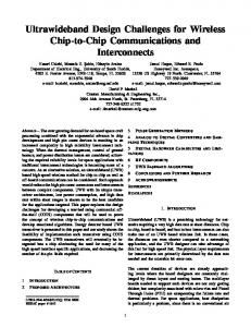
2.1 Approach The study of the effect of multiple ground bumps is closely related to the transmission line launch. A three ground bump configuration is analyzed with the purpose of creating a pseudo-coaxial vertical interconnection and achieving a better match with the transmission line launch. A proper impedance match of the CPW line with the vertical coaxial structure can improve performance. The two transmission line geometries analyzed are illustrated in Fig. 1. Because of the modal transition from coplanar waveguide mode to the TEM coaxial mode, better performance is expected from the modified radial CPW structure. The method includes full wave simulations and microwave measurements. The FEM simulation engine has been calibrated with test structure measurements for the non-radial configuration and very good agreement has been obtained. A picture of the test structures and comparison between
measurements and simulations for package return loss are presented in Fig. 2. The frequency response is shifted towards lower frequencies for the simulated structure because longer transmission lines have been used in the simulation.
Fig. 1. The two basic ground bump configurations used in the design of experiment. Bump diameter = 50 µm and bump height = 25 µm
Fig. 2. Test structures and measurement vs. simulation result for non-radial three bumps 2.2 Factorial design Experiments are performed by investigators in virtually all fields of inquiry, to discover something about an unknown phenomenon or system. A designed experiment is a series of tests in which a set of input variables are purposely changed so that the experimenter can observe and identify the reasons for changes in the output response. If the experiment is correctly conducted, valid and objective conclusions are obtained for the system. The most complete strategy when dealing with several factors is a full factorial experiment [5]. The effect of a factor is defined as the change in response produced by the change in the level of the factor. For the multiple ground bump analysis, the two input variables are number of bumps at four levels (1, 2, 3 and 4) and CPW transmission launch configuration at two levels (radial and non-radial). The full factorial experiment consists of 2 × 4 = 8 treatment combinations. The output variable is chosen to be |S11| at 20 GHz, and the results of the 8 simulations performed under identical conditions, except the input variable variation, are presented in Table 1. The last column shows the value of the output. These have been statistically analysed and the F-statistic [5] calculated. The results of the statistical analysis are presented in Table 2, with the value of the F-statistic on the last column. Variables with higher F are more statistically significant. The threshold value for statistical significance has been calculated to be 3.2 for this application [5]. The calculated F-statistic values for the two variables are 8.2 for number of bumps and 515.6 for the CPW configuration. They are both above the threshold, but
the transmission line launch has a much higher level of significance. The radial configuration performs better because of the matching of the coplanar transmission line with the pseudo-coaxial vertical transmission structure. The Finite Difference Time Domain (FDTD) [6] technique has also been used for the full-wave modelling of the flip chip structures. To enhance the accuracy of the results, Haar wavelets of order 0 and 1 were added close to the bumps, leading to a Haar-based Multi Resolution Time Domain (MRTD) adaptive scheme [7] with only a minimal computational overhead, while providing locally four times higher resolution. The comparative results of the FEM and MRTD simulations for nonradial three ground bump configuration in 1 to 40 GHz frequency range is presented in Fig. 3. Run 1 2 3 4 5 6 7 8
Number of bumps 1 1 2 2 3 3 4 4
Transmission line launch Radial Non-radial Radial Non-radial Radial Non-radial Radial Non-radial Table 1. Experiment
|S11| at 20 GHz -13.91 -12.22 -14.2 -12.13 -14.46 -12.67 -14.34 -12.53
Source Sum of Squares Degrees of freedom Mean Square F statistic .323 3 .108 Number of bumps 8.207 6.771 1 6.771 Transmission line launch 515.574 3.940E-02 3 1.313E-02 Error 1423.850 8 Total Table 2. Statistical output: F statistic represents the significance level for the input variables -5 -10 |S11| (dB)
-15 -20 -25 -30
FEM MRTD
-35 -40
0
5
10 15 20 25 30 35 40 Frequency (GHz)
Fig. 3. MRTD validation of FEM simulations
3
Multiple signal bumps
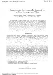
Analysis of the influence of multiple signal bumps has been previously performed for bumps aligned with the transmission path. Results showed worse performance with the increased number of bumps [2]. In this paper, a separate analysis has been performed for multiple signal bumps. We analysed a configuration with the signal bumps aligned with the ground bumps, as shown in Figure 4. The field transition from the coplanar mode to the vertical transition is affected by the proximity of the signal bump to the edge of the signal line with increased number of bumps. The analysis includes one, two and three signal bumps. The bumps have 50 µm diameter and are 25 µm high. The FEM simulations of |S11| for structures including one, two and three bumps are presented in Fig. 4.
The multiple bumps show degraded performance in the 1 to 20 GHz frequency range. For the signal line, the number of attachment bumps should be kept as low as possible.
Fig. 4. Multiple signal bump configuration and |S11| results for one, two and three bumps. The bump diameter is 50 µm and diameter is 25 µm
4
Conclusion
A novel approach for flip-chip design rule development has been presented. The method is based on proper design of a factorial experiment and statistical analysis of the output. The influence of multiple signal and ground bumps on the electrical performance of the flip chip assembly has been analysed. For multiple ground bumps, proper bump placement and matching of the coplanar waveguide transmission line launch with the pseudo-coaxial vertical transition can improve return loss performance. The use of a modified CPW structure brings 2 dB improvement in return loss in the 1 to 40 GHz frequency range. For the signal bumps, best performance is achieved with one bump and the return loss is degraded by one dB for each additional bump. The method presented is very flexible and extendable to a thorough design rule set for RF and microwave flip chip.
References [1] K. Boustedt, “GHz flip chip – an overview”, 1998 Electronic Components ad Technology Conference, Seattle, WA, pp. 1280-1285.. [2] N. Iwasaki, F. Ishitsuka, K. Kato, “High performance flip chip technique for wide-band modules”, 1996 Proceedings of Electrical Performance of Electronic Packaging, Napa, CA, pp. 207-209. [3] R.W. Jackson, R. Ito, “Modeling millimeter wave IC behavior for flipped-chip mounting schemes”, ”, IEEE Trans. Microwave Theory Tech., vol. 45, no. 10, October 1997, pp. 1919-1925. [4] D. Staiculescu, H. Liang, J. Laskar, J. Mather, “Full wave analysis and development of circuit models for flip chip interconnects”, 1998 Proceedings of Electrical Performance of Electronic Packaging, West Point, NY, pp. 241-244. [5] Douglas C. Montgomery, “Design and analysis of experiments”, J. Wiley & Sons, 1996. [6] A. Taflove, "Computational Electrodynamics", Artech House, MA, 1995. [7] E.Tentzeris, R.Robertson, A.Cangellaris and L.P.B.Katehi, "Space- and Time- Adaptive Gridding Using MRTD", presented in the 1997 IEEE Symposium on Microwave Theory and Techniques, pp.337-340, Denver, CO.