Due to their critical registering and redirection mechanisms, MIP and MIPv6 may be ..... FQDN (Fully Qualified Domain Name) ofMN, any eN can get the MN's.
8 FOR A SECURE MOBILE IP AND MOBILE IPV6 DEPLOYMENT
Maryline Laurent-Maknavicius
INTILOR, 9 rue Charles Fourier, 91011 Evry, France
Abstract:
This paper addresses the security problems raised by the introduction of Mobile IP and Mobile IPv6 protocols into existing networks. First, a protocolbased analysis highlights several malicious attacks like masquerade, and denial of service. Then a classical network architecture is studied for the best placements of mobility entities from the security point of view. Firewalls and, possibly NATINAPT devices should take into account the mobility dimension. Impact on the filtering rules enforced within a firewall is presented with inherent security risks. Solutions for the mobile behind a NATINAPT device to remain reachable are exposed with introduced security weaknesses.
Key words:
Mobile IP, Mobile IPv6, Security
1.
INTRODUCTION
Mobile IP (MIP) [1] and Mobile IPv6 (MIPv6) [2] are protocols designed respectively for IPv4 and IPv6 to allow mobiles to be reached and to reach correspondents, wherever they are located, in their home network or in a visited network. The risk is that a host in the home network thinks the mobile is at home, and sends private data to the mobile. If the mobile is located in an untrusted network or data transfer is done through an untrusted network, secrets might be disseminated. Actually, the difficulty is that the security perimeter usually considered for security policy definition is not based on physical network boundaries. That is, the logical network is spread over several networks. This raises the problem of ensuring the end-to-end data confidentiality and the problem of filtering the mobile traffic within the home and visited networks. M. A. Ghonaimy et al. (eds.), Security in the Information Society © International Federation for Information Processing 2002
Part Two: Standards of Information Security
110
Due to their critical registering and redirection mechanisms, MIP and MIPv6 may be subject to attacks such as mobile spoofing, and mobile's traffic redirection. Some security mechanisms are already introduced as mandatory in the standards and drafts. Others should be defined and configured by the security officer using specific equipments such as firewalls, and IPsec. After introducing MIP and MIPv6 in sections 2 and 3 possible attacks linked to the use of MIP or MIPv6 are addressed in section 4. Section 5 describes the security policy requirements for the home and visited networks, and presents a classical network architecture for which the best placements of the mobility entities are studied from a security point of view. The next two points address the incompatibility problems between the mobility protocols, and the firewall (section 6) and NATINAPT devices (section 7). The challenge is to define security filtering rules that support the MIP and MIPv6 processing without affecting the local security policy. If NAT is present, the difficulty is for the mobiles to remain reachable while connected behind a NAT device and to still provide data with security services. Section 8 gives conclusions and section 9 useful references.
2.
MOBILE IP (MIP)
MIP [1] is a macro-mobility "universal" solution based on IP addresses: the Mobile Node (MN) has a permanent home address on its home link and gets temporary care-of addressees) from visited links. This home address enables MN to be uniquely identified. A router on its home link named the Home Agent (HA) maintains a cache where care-of addresses are registered. When away from its home network, MN should detect first that it has moved through for instance the agent discovery mechanism which is an extension of the ICMP router discovery mechanism. That is, local routers send periodic Agent Advertisement messages including the IP address of router(s) on the same subnet along with the subnet prefix. In particular, one router named a Foreign agent (FA) advertises as managing IP mobility. MN should then form a care-of address. Two possible modes are available: - the foreign agent care-of address is one of the FA's IP addresses assigned to MN through the Agent Advertisement messages. This mode is useful when the IPv4 address space is limited since many MNs attached to this FA may be assigned the same care-of address. - the co-located care-of address is acquired by MN dynamically using for instance DHCP (Dynamic Host Configuration Protocol). MN should register its new care-of address to its HA and FA using the registration mechanism which is formed of two UDP registration messages. MN sends a Registration Request message to its HA until HA returns a Registration
For a Secure Mobile IP and Mobile IPV6 Deployment
111
Reply message. Then the association between the MN's home address and careof address which is named a "binding" is registered in the HA' s binding cache. FA which processes the registration messages registers also the link layer address of MN along with the HA' s address. After registration, HA forwards to MN via a tunnel packets addressed to the MN's home address. For the foreign agent care-of address mode, FA is the endpoint of the tunnel and, after decapsulating the tunneled datagrams, it should deliver the inner datagrams to MN. For the co-located care-of address mode, MN is the endpoint of the tunnel and should decapsulate the datagrams itself. To reach a Correspondent Node (CN), MN may tunnel its packets via HA doing reverse tunnelling [3], or it may send packets directly to CN with its care-of address as the source address. To avoid spoofing during registration, MIP requires that one security association is previously agreed between MN and HA, and optionally two others between MNIFA and between FAlHA. As such, in [I] all Registration Request and Reply messages exchanged between those two parties are authenticated based on specific MIP extensions. The Mobile-Home extension is mandatory wheras the Mobile-Foreign and Foreign-Home extensions are optional.
3.
MOBILE IPV6 (MIPV6)
The main difference between MIP and MIPv6 is that MIPv6 is mandatory in any IPv6 stack. The MIPv6 architecture does not include Foreign Agents as the co-located care-of address mode is the only one available in MIPv6. Move detection is performed for instance by the ICMPv6 Neighbor Discovery mechanism. The care-of adress is formed by MN using either the stateless or stateful (e.g DHCPv6) address autoconfiguration. The registration mechanism employed in MIPv6 is named binding update and is encompassed as two options of the destination extension header, the Binding Update option to ask HA to register the MN's current position and the Binding Acknowledgement option for the HA's acknowledgement. Contrary to MIP, MN may send a Binding Update to any CNs to make them update their binding cache, and the CN provided with the MIPv6 protocol may respond using the Binding Acknowledgement option. At any time, HA may ask MN to refresh the binding cache by sending a Binding Request destination option. Upon reception of packets addressed to the visiting MN, HA should tunnel the traffic to MN. Contrary to MIP, CN and MN are allowed to exchange packets directly without passing through HA. This feature is usually referred to as routing optimization. For its CN to identify the packet's origin, MN should then indicate its home address in a Home Address destination option.
112
Part Two: Standards of Information Security
The authentication service is mandatory for the Binding Update and Binding Acknowledgement options whereas the Binding Request option is not authenticated as its processing can never affect the binding cache. For the former two options, at least one security association should be negotiated between HA, eN and MN either manually or thanks to the Internet Key Exchange (IKE) protocol. The authentication service is provided either by a mechanism internal to the binding option processing or the Authentication Header (AH) protocol [4] of the IPsec protocol [5]. More precisely, the IESG (Internet Engineering Steering Group) recently considered that IPsec is too greedy in terms of message flows, AH header processing ... to apply in the mobility context and encourages the IETF to find an alternate security approach. Indeed, IPsec is no longer an explicit authentication means in version 14 of MIPv6 [2], but according to the IETF mobile-ip mailing list, next drafts are highly likely to integrate IPsec again. In this article, we consider that authentication may be ensured either by internal MIPv6 mechanisms or IPsec.
4.
PROTOCOL-ORIENTED PROBLEMS
Attacks specific to MIP and MIPv6 are outlined and classified as occuring during the registration mechanism, or the data transfer. [6] describes some of those attacks in the MIPv6 context and proposes one classification of threats and one classification of attackers.
4.1
Registration
Thanks to the security services offered in the MIP registration and MIPv6 Binding Update messages, attacks based on the registration protocol are mainly limited to the DoS attacks. Firstly, the attacker can flood HA, or CN (for MIPv6) with a large number of Registration Request or Binding Update messages so that HA or CN is unable to process legitimate registration requests. Secondly, the attacker can flood MN with Registration Reply, Binding Acknowledgement or Binding Request messages at a very rapid rate leading to the MN's unreachability. Thirdly, he can intercept all the Binding Update and Registration Request messages addressed to HA so that MN remains unreachable. If all the Binding Update messages addressed to CN are intercepted, MN will still be reachable with the traffic transmitted by eN going through HA. To make MN unreachable, another possibility not specific to the mobility protocol is to inject an ICMP unreachable for an MN's care-of address to HA or eN (for MIPv6 only). This leads to the invalidation of the binding cache entry for MN. To redirect the registration messages and subsequent data to its station,
For a Secure Mobile IP and Mobile IPV6 Deployment
113
an attacker located on the same link than MN can inject an ICMP redirect message.
4.2
Data Transfer
Data in transit may be subject to disclosure, tampering, replay, spoofing, etc. The protection of data is a matter of the security policy applied in a company and the data sensitivity level. The IPsec protocol is one possible security solution which requires that security associations are negotiated between MN and CN. To protect the traffic exchanged between MN and any CN of the home network, another solution is to configure a secure tunnel between the router at the home network boundary and MN. This solution requires that two security associations are established, one between MN and HA for MN and HA's authentication during registration, and one between the router and MN for intensive data protection.
5.
ACHITECTURE-BASED PROBLEMS
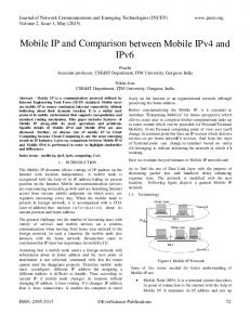
For the MIP/MIPv6 successful deployment, visited companies are required to open their network to untrusted mobile terminals. This means that the security perimeter is no longer based on physical boundaries and that the security policy should integrate the mobility dimension. As depicted in figure 1, the untrusted network for the visited administrative domain includes the external network and MN, whereas the home administrative domain may trust or not its MNs .
~
Unlrusled nelwork
. . Usually pan oflOO lrusled nelwork
Figure 1. The untrusted network considered by the visited domain (left side) and by the home domain (right side)
Even if widely opened to MNs, the visited domain should restrict the access to its network to avoid malicious MNs to originate intrusions from its network. For MIP, MNs are authenticated by FA thanks to a shared security association. For MIP in the co-located care-of address mode and for MIPv6, the inexistence of FA requires that the visited domain trusts the home domain and has confidence in the MNs' authentication performed by HA. In an intranet
114
Part Two: Standards of Information Security
environment, visited and home networks trust each other; they may secure their exchanges through IPsec tunnels; as such, those networks that may be considered as part of the same trusted VPN network are isolated from the untrusted network. Trusting a remote HA is sometimes annoying for the visited domain as HA and FA are not assumed to know each other. For security improvement in the mobility context, the IETF defined some AAA (Authentication, Authorization, Accounting) concepts and a new MIP-based architecture [7] that help the visited and home domains to establish security associations and perform authentication. According to the hereabove discussion, the security policy enforced in the visited domain should observe the following rules: - The trusted visited network part (network equipments, servers, FA, terminals) should be protected against intrusions performed either from MN, or the external network. - The visiting MN is considered as an untrusted terminal and is given restrictive access to internal applications. - The MN's protection from external intnIsions is optional, but recommended to avoid MN to serve as the origin of an external or internal intrusion. - The security policy applied should not affect the mobility protocol. For the home network, the security policy should: - Ensure the protection of the internal network equipments, servers, HA, and terminals. - Protect MN wherever it is located. - Protect communications between the home network and MN. - Not affect the mobility protocol. Two problems should be considered. One is the positioning of MN, FA and HA in the visited and home networks. The second one, as solved in section 6, is the filtering rules implemented in the frrewalls. The remaining part of this section is relative to the best positioning of MN, FA and HA within the visited and home networks which are chosen provided with a screened-subnet firewall and its associated DMZ (Demilitarized Zone). This particular architecture was selected for its popUlarity and its superior security features. FA and HA are hosted by routers which are attached to the visiting MN's link and MN's home link. Each possible placement for FA, HA and MN is identified by a number.
5.1
Visited Network's Architecture
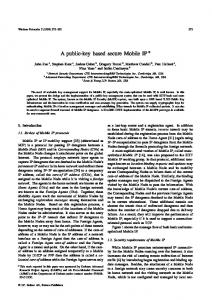
Figure 2 describes seven possible placements for FA and MN in the visited network, for the MIP foreign agent care-of adress mode. For the MIP co-located care-of address mode and MIPv6, only four placements (MNI, MN3, MN3', MN4) are considered with FAI, FA3 and FAS not present.
115
For a Secure Mobile IP and Mobile IPV6 Deployment
E.lcmal nelwork
Figure 2. Placement o/the FA and MN in the visited network
Placement 1: is not secure at all since MNI has direct access to the internal network and may, for instance, connect to internal sensitive servers. Placement 2: is better than placement 1 as traffic filtering rules may be configured in router FA2 to deny any packets from MN2 addressed to internal equipments, and to permit only traffic exchanged between the DMZ and the MN2 link. Then, for MN2 to get access to the internal network, subversion of FA2 is required. Placement 3: MN3 is directly connected to the DMZ. The internal network is protected thanks to router R configured with filtering rules. Router R for instance, may deny any inbound packets with a source address belonging to the pool of addresses assigned dynamically to mobiles in the DMZ. The security problem of MN3 is that equipments in the DMZ are sensitive to direct attacks from MN3, that is, either the mobile users or a emote intruder in MNs. Protection of MNs in MN3 or MN3' is ensured by router R'. Supported filtering rules should only permit inbound packets with a destination address either reserved to MNs or assigned to an internal equipment positionned in the DMZ. Other problems are specific to the foreign agent care-of address mode and router R' supporting FA3's functions (e.g. registering, tunneling, optional security association management, and MN's and HA's authentication). Firstly, routing and filtering perfonnances of router R' may be affected due to the FA3's processing overhead. Secondly, a successful intrusion in R' will likely affect FA3, and the visited MNs' reachability. Placement 4: The internal network benefits from the same level of protection than in placement 3 (MN3) with router R applying the same rules for the inbound traffic addressed to the internal network. The MNs are better protected from the external network since MNs are behind router R and specific filtering rules for MNs may be defined in router R. Even the DMZ is more secure since all the equipments in the DMZ are under the visited domain control and are assumed to be securely configured to limit the intrusions. Moreover, those equipments are protected from possible intrusions from MNs thanks to router R. Like for router R' in placement 3, router R perfonnances may be affected by the FA4's functions processing.
116
Part Two: Standards of Information Security
Placements 4, 6, 7: Compared to placements MN3, MN4, and MN3 ', placements 5, 6, and 7 offer a better isolation of MNs from possible intrusions from the external network, and placements 5 and 6 a better isolation of the internal network from possible MNs' attacks. As a conclusion, it appears that the best placements of FA and MN from a security point of view are placements 4,6,7 and 3 (MN3' only).
5.2
Home Network With Trusted MNs
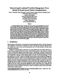
MN is considered at home only when connected to its home link. That is, while in its home network, MN can be a visitor since MN may move from one sub-network to another one. If trusted in the visited sub-network, MN connects locally. Otherwise, the above studied visited network scheme applies to the visited sub-network. When at home, MN behaves as a trusted stationary terminal in the internal network and HA is either in the internal network (HA 1) or located in router R (HA2) as shown in figure 3. HAl benefits from the following advantages. (1) HA 1 and MN s while at home are protected from the untrusted network by the screened-subnet firewall. (2) packets originating from an external CN and addressed to MN are filtered by the firewall even if MN is away from its home network. For MIP, filtering is done for all packets. For MIPv6, such filtering is performed if eN has not registered yet the MN's position and is limited to the first IP packets since subsequent packets are sent directly to MN.
External
""'work
Figure 3. Placements of HA in the home network
Placement HA2 has the same advantages, but router R's performances may suffer from the HA2's processing overhead as HA2 is responsible for registering, tunneling, security association management, and MN authentication.
5.3
Home Network with Untrusted MNs
As untrusted terminals, MNs should be located between the internal and external networks. As such, HA is either in the DMZ (HA4), in other links
For a Secure Mobile IP and Mobile IPV6 Deployment
117
(HA5, HA6) or within routers (HA2, HA3). The problem of such approaches are very similar to those explained in section 5.1. That is, HA and MNs may be subject to intrusions, and performance problems for HA2 and HA3 may happen. As such, the best placements are HA5, or HA6. Having MN outside the internal network in placements HA5, HA6, HA2 and HA3 does not mean that employees should physically go to a specific room to connect their mobile. One can imagine that a wireless LAN (i.e. 802.11) covers all the company's internal offices and serves to connect MN to the appropriate outside link of the DMZ. However, if the company is too largely spread to be covered by one access point, then another access point should be wired to the DMZ. The second drawback is that MN may be connected to the wrong network, and dynamicaly obtain an address for later packet transfers.
6.
FIREWALL TRAVERSAL
The challenge is to define filtering rules that implement the local security policy while not disrupting the MIP or MIPv6 protocol. Those filtering rules should apply to frrewalls handling the mobility traffic, for instance router R of figure 3 for HA 1 placement, or router R' of figure 2 for MN3' placement. Three problems of compatibility between MIPIMIPv6 and classical filtering rules applied in a basic frrewall (a screening router) are discussed below. Basic anti-spoofing rules are not compatible with MIP in the foreign agent care-of address mode. Indeed, anti-spoofmg rules should: - deny outbound packets with external source address deny inbound packets with internal source address, - deny inbound packets with private source address. As such, if a visiting MN sends packets to eN in its home network with its home address as the source address, the ingress router of the visited network should block the packets. If not, the egress router of the home network should block them. The solution known as the IP within IP encapsulation is to use the tunnel and reverse tunnel between FA and HA and to encapsulate any IP packets. The filtering in the home and visited networks is then done on the addresses of the outer IP header (i.e. FA and HA's addresses), and if IP-in-IP encapsulation is allowed, packets are no longer blocked. As such, this IP tunnel may serve to bypass the filtering rules and provides a means for data leaks. Another problem for the home network's egress firewall (FW2 in figure 4) is how to identify MN while away from home. For instance, assume that this firewall implements a VPN and limits home network's exchanges to predefined remote networks, and MN is not connected to one of those networks. MN is reachable by a care-of address (Co@) in the visited network, and sends packets to its home network for first registering as depicted in figure 4. FW2 blocks
Part Two: Standards of Infonnation Security
118
these packets based on the source IP address. As such. MN moves are limited to authorized remote networks unless FW2 processes the MIPv6 Binding Update destination option or the Home Address destination option. and MIP inner packet's source and destination addresses.
Home network
Visited network
Registration
MIP foreign agent cllre·of address
MIPv6
Figure 4. Classical MIP and MIPv6 packet formats as received by FW2 during MN's registering (left side) and data transfer (right side) when the reverse tunneling applies
7.
NATINAPT TRAVERSAL
Because NAT and NAPT (Network AddresslPort Translation) functions are widely deployed today in IPv4 network. problems of incompatibility between NA TINAPT and MIP should be studied. This NA TINAPT traversal issue is specific to IPv4 since IPv6 provided with 16-octet address fields is not concerned by the address starvation problem. Three basic solutions for the NAT traversal are presented below followed by some security comments and the possible IPsec support analysis. Assume that the visited network is provided with a NATINAPT device. and the visited MN acquires a private care-of address. The private care-of address is passed to HA through a registration request message. Because private addresses are non-routable. HA will not be able to forward packets to this care-of address and connectivity with MN will be lost. It should be noted that HA and FA. if any. should always be assigned a public address to be reachable from the public iletwork. This implies that the NATINAPT function is either integrated into the HAIFA equipment or does maintain a fixed address binding for HAIFA to remain reachable.
For a Secure Mobile IP and Mobile IPV6 Deployment
119
Various solutions are proposed in the literature [8] and by the IETF [9], [10], [11]. Three main approaches are identified as follows. - The NAT device in the visited network maintains the binding between the private address of the MN in the visited network and the MN's home public address so that packets issued from MN are transmitted by NAT over the public network with the home public address of MN as the source address. In [8], the home and visited networks are assumed to do NAT translation and the NAT function is hosted in the FA and HA equipments. [8] considers only the foreign agent care-of address mode. To retrieve the public address of MN, FA asks its HA to assign one available public address to MN using new UDP messages. From the knowledge of the FQDN (Fully Qualified Domain Name) ofMN, any eN can get the MN's home public address through DNS requests. - A UDP tunnel is established between HA and MN for IP packets to be seamlessly exchanged through the NAT device of the visited network. The NAT traversal is detected by HA by comparing the MN's co-located careof address against the source address of the received packets. Thanks to two vendor-specific extensions for the registration request/reply messages, a tunnel is established - A UDP tunnel is established locally to the visited network [11]. That is, a MIP proxy is introduced as a dual-homed host in the DMZ between the NAT device and HA. The basic ideas are that the MIP proxy behaves as HA for MN and as MN for HA, the MN's care-of address is the public address of the NAT device, and a UDP tunnel is established between MN and the MIP proxy. The drawback of [11] is that the MIP proxy should belong to the same administrative domain than HA since HA handles the traffic issued by the MIP proxy as if it was transmitted by MN. It should be noted that the latter two approaches work only in the co-located care-of address mode as the endpoint of the tunnel should be MN and not FA. One drawback of those tunneling approaches is that they provide a means for bypassing filtering rules as explaned in section 6. For the third approach, this can be solved by filtering the traffic in the MIP proxy or between the proxy and HA. The risk of the first approach is that MN's packets transmitted by NAT are rejected by the public network's access router implementing anti-spoofing filtering rules (cf. section 6). IPsec protocol that can be used for instance to protect data in transfer (cf. section 4.2) may suffer from incompatibility problems with NAT. Indeed, the AH header in the transport mode [4] introduces authentication data calculated over the packet's addresses. Since the NAT modifies one of the packet's addresses, the receiving IPsec device must consider the packets as invalid and proceed to packets rejection.
120
8.
Part Two: Standards of Information Security
CONCLUSIONS
From a security point of view, this is a real challenge to introduce mobiles in existing networks. Network topology changes may be necessary for the mobiles to have their own access point. Filtering rules should be revised to avoid disrupting the MIPIMIPv6 processing, but the minimum set of equipments should be updated with these new rules. In order to preclude filtering rules to be bypassed in case of IP-within-IP tunneling (e.g. for NAT traversal), more sophisticated frrewalls able to filter inner IP packets should be introduced. Mobility protocols are based on the strong requirement that the visited domain trusts the home domain. For a more secure mobility solution, the IETF developed the AAA (Authentication, Authorization, Accounting) concepts and a new architecture for the visited domain to authenticate securely the mobiles. One idea proposed at the IETF is that one AAA entity processing mobile authentication is associated to the firewall in the filtering process for defining dynamic filtering rules for the mobility traffic. What is not defined at the IETF is the relationship between the frrewall and the AAA entities, and the protocol implementing the AAA concepts in the IPv6 environment.
9.
REFERENCES
[1] c. Perkins, IP Mobility Support, Standards Track, RFC2002, October 1996. [2] D.B. Johnson, C. Perkins, Mobility Support in IPv6, draft-ietf-mobileip-ipv6-14, July 200l. [3] G. Montenegro, Reverse Tunnelingfor Mobile IP, revised, rfc3024, Jan. 2001. [4] RFC 2402, S. Kent, R. Atkinson, IP Authentication Header, November 1998. [5] RFC 2401, S. Kent, R. Atkinson, Security Architecture for the Internet Protocol, November 1998. [6] A. Mankin, B. Patil, D. Harkins, E. Nordmark, P. Nikander, P. Roberts, T. Narten, Threat Models Introduced by Mobile IPv6 and Requirements for Security in Mobile IPv6, draft-ietf-mobileIP-mipv6-scrty-reqts-Ol, October 200l. [7] P.R. Calhoun, G. Zorn, P. Pan, H. Akhtar, Diameter Framework Document, draft-ietf-aaa-diameter-framework-Ol, March 2001. [8] T. Kato, A. Idoue, H. Yokota, Mobile IP Using Private IP Addresses, 6th IEEE Symposium on Computers and Communications, 2001, pp. 491-497. [9] O. H. Levkowetz, J. Forslow, H. Sjostrand, NAT Traversal for Mobile IP using UDP Tunnelling, draft-Ievkowetz-mobileip-nat-tunnel-OO, July 2001. [10] S. Vaarala, Mobile IP NATINAPTIFirewali Traversal, draft-vaarala-mobileipnat-traversal-OO, July 200l. [11] F. Adrango, P. Iyer, Mobile IPv4 Traversal Across NAT and VPN Gateway, draft-adrangi-mipv4-midbox-traversal-00, July 200l.