a polycondensed silane network with two kinds of functional groups: fluorocarbon groups .... FSL oil,17 and each water phase contains the surfactant Zonyl FSN-.
COMMUNICATION
www.rsc.org/loc | Lab on a Chip
Functional patterning of PDMS microfluidic devices using integrated chemo-masks† Mark B. Romanowsky,a Michael Heymann,bc Adam R. Abate,a Amber T. Krummel,a Seth Fradenc and David A. Weitz*a Received 9th March 2010, Accepted 28th April 2010 First published as an Advance Article on the web 7th May 2010 DOI: 10.1039/c004050a
Microfluidic devices can be molded easily from PDMS using soft lithography. However, the softness of the resulting microchannels makes it difficult to photolithographically pattern their surface properties, as is needed for applications such as double emulsification. We introduce a new patterning method for PDMS devices, using integrated oxygen reservoirs fabricated simultaneously with the microfluidic channels, which serve as ‘‘chemo-masks’’. Oxygen diffuses through the PDMS to the nearby channel segments and there inhibits functional polymer growth; by placement of the chemo-masks, we thus control the polymerization pattern. This patterning method is simple, scalable, and compatible with a variety of surface chemistries. The material of choice for many kinds of microfluidic devices is PDMS. Using soft lithography, it can be molded quickly, easily, and at low cost.1 Additional advantages of PDMS include its gas permeability, which makes it useful in cell patterning or culturing applications,2 and its low elastic modulus, which makes it useful for devices incorporating valves.3,4 Increasingly complex, integrated arrays of devices and components have been demonstrated.5,6 However, some microfluidic applications require spatially patterned surface properties; for example, double emulsions (drops within drops) can generally be made only in channels whose wettability switches abruptly between hydrophilic and hydrophobic.7,8 This kind of functional patterning remains challenging for PDMS devices, despite the many surface modification methods now available.9 Individual double emulsion makers have been patterned via photopolymerization, by passing light through a photo-mask10,11 or by a finely focused beam of light,12 but both these methods require precise alignment of the mask or beam to the microfluidic channels. This alignment is a major hurdle for larger devices or device arrays, due to the softness of PDMS. To functionally pattern a cm-scale array at mm-scale precision, the photo-mask must be aligned with the microchannels to 1 part in 104, but PDMS is so soft that even small
a School of Engineering and Applied Sciences/Department of Physics, Harvard University, Cambridge, Massachusetts, USA. E-mail: weitz@ seas.harvard.edu; Tel: +1 617-495-3275 b Biophysics and Structural Biology Program, Graduate School of Arts and Sciences, Brandeis University, Waltham, Massachusetts, USA c Department of Physics, Graduate School of Arts and Sciences, Brandeis University, Waltham, Massachusetts, USA † Electronic supplementary information (ESI) available: Additional micrographs showing effects of sub-dominant design parameters and non-photo-initiated surface chemistry, and microfluidic device designs in AutoCAD and PDF formats. See DOI: 10.1039/c004050a
This journal is ª The Royal Society of Chemistry 2010
stresses can distort it beyond this tolerance. Moreover, PDMS is known to shrink during curing: devices are smaller than their soft lithography masters by 1–2% in linear size, and the amount of shrinkage depends on the details of the elastomer base–crosslinker mix and the curing conditions.13 Therefore a photo-mask must be tailored not only to a specific device design but also a highly specific fabrication protocol. To address these difficulties, an improved functional patterning method for PDMS is needed. In this paper, we introduce a new method for patterned surface functionalization of PDMS microfluidic channels using integrated ‘‘chemo-masks,’’ which exploits the gas permeability of PDMS. The chemo-masks are oxygen reservoirs near but not connected to the fluid channels, molded in the elastomer during the same soft lithography process. Oxygen diffuses out of the reservoirs and inhibits polymerization in the nearby channel segments, thereby imposing a chosen polymer growth pattern. The chemo-masks and flow channels are molded simultaneously, so the alignment step and specialized optics needed by photo-mask techniques are avoided. The chemo-masks automatically scale identically with the channels, so elastomer strain and shrinkage become unimportant. The chemomasks function independently of the particular chemistry initiating the polymerization, so non-photo-initiators can be used instead of photo-initiators, allowing us to pattern polymer growth even without a UV light source. We show that the chemo-mask method works robustly in a range of device geometries, and show its utility by using it to make devices to produce double emulsions of both water–oil– water and oil–water–oil types. We demonstrate the chemo-mask method using simple microfluidic devices, consisting of one flow channel plus one set of chemomasks, shown in Fig. 1a (see also ESI†). A straight channel of width 30 mm is abutted, along a segment of length L, by two rectangular chambers separated from the channel by a thin wall of thickness 20 mm. The rectangular chambers have width 1500 mm, which together with their length controls the amount of atmospheric oxygen they contain. All features are 50 mm high. We make the devices from PDMS using standard soft lithography methods.3 We remove the PDMS from the master, punch inlet and outlet holes for the channels, and plasma bond to a glass slide. The PDMS and glass slide are removed from the plasma source before being brought together, so air is trapped in the chemo-mask chambers. We functionalize the channels with two further steps. First, we apply a glassy coating using a sol–gel method.12 This coating is a polycondensed silane network with two kinds of functional groups: fluorocarbon groups, which make the coating hydrophobic by default; and photo-initator groups, which will provide surface-bound radicals to initiate polymer growth. Second, we fill the fluid channel Lab Chip, 2010, 10, 1521–1524 | 1521
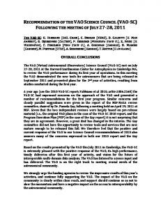
Fig. 1 Device schematic (a, not to scale), and micrographs of patterned devices stained for visualization (b, c, and d). Oxygen diffuses readily from the chemo-mask chamber, through a short interval of PDMS, and into the nearby channel segment, inhibiting polymerization there. Chemo-mask length L is varied to control the channel segment in which polymerization is inhibited: L is 200, 400, and 800 mm in panels b, c, and d. The height of all features is 50 mm. Scale bars denote 100 mm.
with an acrylic acid monomer solution12 and expose the whole device to UV light at intensity 140 mW cm�2 for 10 minutes; this is done in air, without degassing. Poly(acrylic acid) (PAA) grows on all the channel surfaces, and makes them hydrophilic, except for regions close to the chemo-masks. Oxygen, trapped in the chemo-mask chambers during bonding, diffuses through the thin walls into the neighboring channel segments and inhibits the polymerization. A similar inhibition effect has been exploited to make complex polymer particles14,15 and to shape photocurable adhesives using PDMS molds.16 We can suppress the inhibition if desired, allowing polymerization everywhere, by pre-filling the chemo-mask chambers with water. After UV exposure, we flush the channel with water to remove unbound monomer. To visualize the pattern of polymerization, we stain the channel with toluidine blue dye. This stain binds electrostatically only to the surfaces with PAA, darkening the whole channel except for the regions near the chemo-mask where polymerization was inhibited, as shown in Fig. 1b–d. The dye is dissolved at 0.1% (w/w) in pH 8 phosphate buffer solution. We apply the stain for 5 minutes, then flush with water, and purge with air. The length of the inhibited region in the channel corresponds to the length of the chemo-mask chamber, and this length is the most useful design parameter. The wall thickness of 20 mm is an empirical tradeoff between structural stability and permeability: 10 mm walls do not reliably survive fabrication, and 40 mm walls do not reliably pass enough oxygen to fully inhibit polymerization. Other charateristics of the chemo-mask have less influence on the shape of the inhibited region (see Fig. S1–S4 in the ESI†). The width must be large enough to hold sufficient oxygen to inhibit polymerization fully by counteracting all the available initiator molecules, but we see little change with further increase beyond a threshold of about 750 mm. We see negligible change in the inhibited region when varying the feature height from 10 to 50 mm. Chemo-masking may be used to pattern flow channels as wide as 100 mm; wider channels may be incompletely inhibited, especially near the corners of the chemo-mask chambers. To demonstrate the usefulness of the chemo-mask patterning method, we use it to make devices for producing double emulsions. This is a stringent test of the method, because double emulsions can be formed only in devices with a strong and sharp change in 1522 | Lab Chip, 2010, 10, 1521–1524
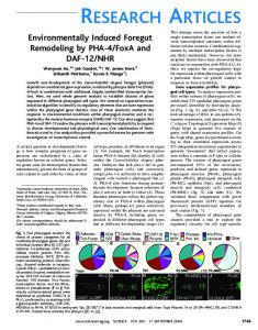
wettability. We use the same patterning protocol as above, except that we reduce UV exposure to 1 minute, which generates enough wetting contrast to make double emulsions. To make water–oil– water double emulsion, we use a device with two consecutive cross junctions. Our chemo-mask is placed near the first junction and the subsequent channel, to keep these regions hydrophobic, while the second junction and the rest of the device becomes hydrophilic. A schematic of the junctions and chemo-mask is shown in Fig. 2a (see also ESI†), and a corresponding micrograph of the device producing double emulsions is shown in Fig. 2b. We use a similar device to make oil–water–oil double emulsions; its chemo-mask covers the second junction and the outlet channel to keep them hydrophobic, while the rest of the device becomes hydrophilic. A schematic and micrograph of the oil–water–oil device are shown in Fig. 2c (see also ESI†) and Fig. 2d, respectively. Both devices stably produce monodisperse double emulsion drops at flow rates of 300/600/1000 mL h�1 for inner/ middle/outer phase. Each oil phase is the fluorocarbon oil HFE-7500 with 1.8% (w/w) of a surfactant, the ammonium salt of Krytox 157 FSL oil,17 and each water phase contains the surfactant Zonyl FSN100 at 0.5% (w/w), or poly(vinyl alcohol) at 5% (w/w). An important advantage of our method over photo-mask methods is that the chemo-masks determine the polymer growth pattern independently of the source of radicals. By contrast, a photo-mask controls the locations where radicals are available, and the radicals in turn control polymer growth. Because the chemo-mask method separates the radical production process from the patterning process, non-photo-initiated polymerization may be patterned in the same way as photo-initiated polymerization. Functionally patterned devices may thus be made without any kind of photo-chemistry. To show this chemical generality, we fabricate devices using the same double emulsion design as in Fig. 2a, but with an alternate surface chemistry, using a non-photo-activated initiator. In the alternate sol–gel coating, we include a silane methacrylate instead of the photo-initiator-silane. The methacrylate groups provide double bonds onto which a polymer chain can anchor. The sol–gel solution comprises tetraethylorthosilicate, methyltriethoxysilane, 3-(trimethoxysilyl)propylmethacrylate, water adjusted to pH 2 with HCl, and ethanol, mixed 1 : 1 : 1 : 1 : 2 by volume; we preconvert,12 dilute 1 : 10 with methanol, and apply to the device as in ref. 12. The This journal is ª The Royal Society of Chemistry 2010
Fig. 2 Schematics of double emulsion devices, and micrographs of the double emulsions produced, in devices made with chemo-masks and photopolymerized poly(acrylic acid), of water–oil–water (a, b) and oil–water–oil (c, d) types. The shaded channel segments in (a, c) grow no polymer, due to the chemo-masks, and thus remain hydrophobic; the rest of the channels become hydrophilic. The circular support posts stabilize the roofs of the chemomask chambers. In both devices the flow rates are 300 mL h�1 in inner phase, 600 mL h�1 in middle phase, and 1000 mL h�1 in outer phase. Scale bars denote 100 mm.
corresponding monomer solution is an aqueous solution of the monomer, acrylamide, at 2% (w/w), and ammonium persulfate (APS) at 0.1% (w/w) and tetramethylethylenediamine (TEMED) at 0.5% (v/v), which together initiate the growth of polyacrylamide on the channel walls. We inject this monomer solution into the coated devices and incubate overnight. To prevent solvent evaporation, we place the whole chip in a glass beaker and cover with more monomer solution. The polyacrylamide grows everywhere, turning the channel walls hydrophilic, except near the chemo-masks; after incubation we purge with air to remove unbound monomer. The resulting device produces water–oil–water double emulsions (see Fig. S5 in the ESI†). Our chemo-mask method makes the functional patterning of PDMS microfluidic devices simpler and more robust than standard photolithographic methods and should facilitate the fabrication of large and complex parallelized devices. Chemo-masks only modestly increase the footprint of typical devices; the chambers can be irregular or non-convex shapes, as is shown in Fig. 2, allowing them to use otherwise unused area for oxygen reservoirs. They should be simple to include in arrays of 100 or more devices per 300 wafer. The chemomask method is suitable for spatial control of any kind of radical polymerization, and therefore enables non-photo-based patterning, widening the range of possible surface chemistries for microfluidics while also eliminating the need for costly UV lamps and optics. Finally, if chemo-masks are placed above and below as well as beside flow channels, it should enable patterning of three-dimensional, This journal is ª The Royal Society of Chemistry 2010
non-planar shapes, in a single exposure; such patterning would be prohibitively difficult or impossible with a photo-mask.
Acknowledgements This work was supported by the Massachusetts Life Sciences Center, BASF, the NSF (grants DBI-0649865 and DMR-0602684), the Harvard MRSEC (grant DMR-0820484), and the Brandeis NSF MRSEC (grant 0820492).
Notes and references 1 J. C. McDonald, D. C. Duffy, J. R. Anderson, D. T. Chiu, H. Wu, O. J. A. Schueller and G. M. Whitesides, Electrophoresis, 2000, 21, 27–40. 2 A. Zanzotto, N. Szita, P. Boccazzi, P. Lessard, A. J. Sinskey and K. F. Jensen, Biotechnol. Bioeng., 2004, 87, 243. 3 M. A. Unger, H. Chou, T. Thorsen, A. Scherer and S. R. Quake, Science, 2000, 288, 113. 4 A. R. Abate, M. B. Romanowsky, J. J. Agresti and D. A. Weitz, Appl. Phys. Lett., 2009, 94, 023503. 5 T. Nisisako and T. Torii, Lab Chip, 2008, 8, 287–293. 6 M. Rhee and M. A. Burns, Lab Chip, 2009, 9, 3131–3143. 7 S. Okushima, T. Nisisako, T. Torii and T. Higuchi, Langmuir, 2004, 20, 9905–9908. 8 C.-H. Chen, R. K. Shah, A. R. Abate and D. A. Weitz, Langmuir, 2009, 25, 4320–4323. 9 J. Zhou, A. V. Ellis and N. H. Voelcker, Electrophoresis, 2010, 31, 2– 16.
Lab Chip, 2010, 10, 1521–1524 | 1523
10 Y. Wang, H.-H. Lai, M. Bachman, C. E. Sims, G. P. Li and N. L. Allbritton, Anal. Chem., 2005, 77, 7539–7546. 11 M. Seo, C. Paquet, Z. Nie, S. Xu and E. Kumacheva, Soft Matter, 2007, 3, 986–992. 12 A. R. Abate, A. T. Krummel, D. Lee, M. Marquez, C. Holtze and D. A. Weitz, Lab Chip, 2008, 8, 2157–2160. 13 J. R. Anderson, D. T. Chiu, R. J. Jackman, O. Cherniavskaya, J. C. McDonald, H. Wu, S. H. Whitesides and G. M. Whitesides, Anal. Chem., 2000, 72, 3158–3164.
1524 | Lab Chip, 2010, 10, 1521–1524
14 D. Dendukuri, D. C. Pregibon, J. Collins, T. A. Hatton and P. S. Doyle, Nat. Mater., 2006, 5, 365–369. 15 D. Dendukuri, P. Panda, R. Haghgooie, J. M. Kim, T. A. Hatton and P. S. Doyle, Macromolecules, 2008, 41, 8547–8556. 16 D. Bartolo, G. Degre, P. Nghe and V. Studer, Lab Chip, 2008, 8, 274– 279. 17 A. R. Abate, A. Poitzsch, Y. Hwang, J. Lee, J. Czerwinska and D. A. Weitz, Phys. Rev. E: Stat. Phys., Plasmas, Fluids, Relat. Interdiscip. Top., 2009, 80, 026310.
This journal is ª The Royal Society of Chemistry 2010