J. Electron Test (2010) xx:xxx-xxx xxx xx.xxxx/xxxxxx-xxx-xxxx-x
Functional Verification of DMA Controllers M. Grosso W.J. Perez H. D. Ravotto E. Sanchez M. Sonza Reorda A. Tonda J. Velasco Medina
Abstract - Today’s SoCs are composed of a wide variety of modules, such as microprocessor cores, memories, peripherals, and customized blocks directly related to the targeted application. To effectively perform simulation-based design verification of peripheral cores embedded in a SoC, it is necessary to stimulate the devices in a broad range of behavior possibilities, checking the produced results. Different strategies for generating suitable stimuli have been proposed by the research community to functionally verify the modules embedded in a SoC and their interconnection: however, design verification of deeply embedded peripherals, e.g., DMA controllers, is really a challenging task, since their controllability is typically reduced. In this paper we describe a general approach to develop short and effective test programs aimed to the design verification of embedded system peripherals, such as DMA controllers embedded in SoCs, which can also be exploited in later stages for testing, by adding suitable observability features. Experimental results demonstrating the method suitability are reported. Keywords Design verification Test program Set stimuli generation SBST DMA Controller Responsible Editor E. Sanchez · M. Grosso · D. Ravotto · M. Sonza Reorda · A. Tonda Dipartimento di Informatica e Automartica, CAD Group, Politecnico di Torino, Turin, Italy E. Sanchez, e-mail:
[email protected] M. Grosso, e-mail:
[email protected] D.Ravotto, e-mail:
[email protected] M. Sonza Reorda, e-mail:
[email protected] A. Tonda, e-mail:
[email protected] W.J. Perez H. · J. Velasco Medina Bionanoelectronics Group, Universidad del Valle Cali, Colombia W.J. Perez H., e-mail:
[email protected] J. Velasco Medina, e-mail:
[email protected] W.J. Perez H. GIRA Group, Universidad Pedagógica y Tecnológica de Colombia Sogamoso, Colombia e-mail:
[email protected]
1
Introduction
Most Systems on Chip (SoCs) integrate at least one processor core, some peripheral devices, different logic modules, and a variable number of memory cores. Although the SoC design paradigm may simplify the design phase, it also increases the complexity of the audit process related to the methods of validation, verification and testing (VV&T), by decreasing the accessibility of each module into the chip and combining modules from different sources, design styles, and test characteristics. Until now, the research community has devoted considerable efforts to processor core VV&T processes, while integrated peripherals have been less investigated. Naturally, processor cores have focused the research attention due to their area occupation and their primary role in computation and management tasks within the SoC. However, it must be noted that the increasing number and complexity of embedded peripherals strongly characterizes most of the current SoCs. In general, design verification is the process of verifying that all modeled behaviors of a design are consistent with a reference model. The reference model may represent a set of properties that the system needs to fulfill, and usually it is described at a higher abstraction level [1]. Design verification methodologies have been developed in a broad spectrum, ranging from manual verification to formal verification techniques, and including for example random and semi-random approaches. Formal verification uses mathematical techniques to prove the correctness of the design, but it frequently involves counting on enormous computational resources, even for some simplified models. On the other hand, despite the simulation-based methods can never guarantee the complete conformance to specification of formal methods, they are widely used due to the reasonable computational resources required, the grade of details of the circuit behavior that can be simulated and their potential to detect and diagnose
J. Electron Test (2010) xx:xxx-xxx xxx xx.xxxx/xxxxxx-xxx-xxxx-x
faults in different stages of the device VV&T processes [2][3]. In the simulation-based context, it is possible to state that a verifying procedure implies to perform a simulation-based process in which input data (called set of stimuli) are applied to a model of the device under evaluation (called device under test or DUT). Subsequently, the observed and expected behaviors are compared by mean of a response checker that generates pass/fail information regarding the outcome of the comparison [2]. Simulation-based methodologies aim at uncovering design errors by thoroughly exciting the current model of the circuit using suitable sets of stimuli [2], which can be randomly, manually or automatically generated. In any case, the objective is to fully excite all functions of the DUT by employing a reduced number of appropriate data patterns. This issue is a crucial point of the whole methodology, since it strongly affects the cost of the whole VV&T process, and because the simulation of an exhaustive set of data patterns is generally far too expensive [3]. However, determining the appropriate data patterns is a problem-dependent and non-trivial task. In a processor-based SoC, an efficient way to generate the set of stimuli is to use the embedded processor core to execute a specially designed test program whose goal is to make evident the difference between a faulty device and a working one [2]. The introduction of this kind of test programs dates back to the 80s [4], and such techniques have been exploited in the functional self-test approach known as SoftwareBased Self-Test or SBST [5]. The key idea of SBST is to exploit on-chip programmable resources to run normal programs that suitably stimulate the processor itself and/or other devices accessible by it. The processor generates and applies functional-test patterns using only its native instruction set, virtually eliminating the need for additional test specific hardware. The SBST technique provides an effective alternative to traditional testing and self-testing approaches, but it can also complement and/or enhance the test quality provided by these approaches [2][3]. This paper aims at extending SBST methods to the verification of peripherals in charge of providing system services, called system peripherals, instead of pure communication services. System peripherals such as DMA controllers, interrupt controllers, and timers are usually more deeply embedded in the SOC than peripherals devoted to communications services, called I/O peripherals. In particular, this paper presents a method for the generation of suitable stimuli able to thoroughly excite the different functionalities implemented by a typical DMA controller, starting from its functional description,
only. The generation is backed up by coverage metrics gathered exploiting the available device description. The resulting stimuli can be effectively used for the validation and verification of the core design, and later, they may represent an effective starting point for the development of set of stimuli aimed to device testing. The rest of the paper is organized as follows: Section 2 provides some significant background material in the area of SBST techniques for peripheral verification and test, as well as on the metrics used for evaluating the effectiveness of generated stimuli, and outlines the main features of typical DMA controllers. Section 3 describes the method that we propose for generating proper stimuli for DMA controller verification. A case study is presented in Section 4, whereas Section 5 reports some preliminary experimental results gathered on a representative test case. Finally, Section 6 draws some conclusions, and summarizes future research activities in the area. 2 Peripheral verification and test 2.1 Background As mentioned before, most of the available works developed by the research community on VV&T issues mainly tackle processor cores embedded in SOCs. These methodologies resort to functional approaches based on exciting specific functions and resources of the processor. Some of the most representative approaches are briefly described in the following. Psarakis et al. [6] present a comprehensive study about the potential role of software-based self-testing in the microprocessor test and validation process, as well as its supplementary role in other classic functional- and structural-test methods. Additionally, the authors propose a well structured taxonomy for different SBST methodologies according to their test program development philosophy. Alternatively, different approaches to face the test set generation for embedded processors testing using SBST methodologies, taking into account various processor architectures and system environment constraints have been developed in [7 - 13]. Cheng et al. [7] present a technique to test the SoC at the system level using application-based programs. The proposed software application-level verification methodology employs test programs composed of dynamic sequences of code segments. The test programs are automatically generated using a test generator. Experiments were conducted applying this methodology to the Altera Nios SoC. Shen et al. [8] provide an automatic functional test generation method for both manufacturing test and design validation. This methodology is implemented in a program that takes as input the instruction set of the
J. Electron Test (2010) xx:xxx-xxx xxx xx.xxxx/xxxxxx-xxx-xxxx-x
processor and the operations performed by it in response to each instruction, and produce a functional test. Kranitis et al. [9] developed a high-level SBST component-oriented methodology which is based on the knowledge of the ISA and the processor’s register transfer level description. They applied this methodology to two MIPS-compatible processors. On the other hand, different approaches can be found in literature related to peripheral VV&T issues; however, most of them tackle I/O peripherals, only. For example, Bolzani et al. in [14] propose a fully automated methodology for the generation of test programs for peripheral cores (PIA, UART) embedded in a SoC. The methodology is based on the exploitation of the correlation between high-level metrics (Toggle, Expression, Condition, Branch and Statement) and the gate-level fault coverage. Apostolakis et al. [15] present a generic deterministic flow for the application of processor-based testing to communication peripheral cores. In this approach, the test sets for the individual subcomponents of the communication peripheral core are pre-computed and pre-generated. In [16] the authors propose a combination of the approaches presented in [14] and [15] and define a new automatic methodology that has been evaluated on a SoC with three popular communication peripherals such as UART, HDLC and Ethernet. Concerning system peripherals, Dushina et al. [17] introduce a semi-formal based methodology to generate test sets targeting corner cases of the device under test. The device is modeled in a simplified manner and translated into a Finite State Machine (FSM). Each FSM state corresponds to a combination of the coverage variables. Then, a set of abstract tests containing a sequence of states for every case is obtained via a coverage-driven test generator. Finally, every single abstract sequence of states is translated in order to obtain the real test set. This methodology was exploited for the validation of a DMA controller embedded in a RISC-based microcontroller, achieving about 87% of statement coverage and 75% of branch coverage. Then again, two newer approaches were presented in [18] and [19] by Grosso et al. aimed to system peripherals verification, which can be extended also for testing. These works propose a method to develop functional tests for DMA controllers embedded in SoCs, and form the basis for the current approach presented herein. Some preliminary experimental results for an 8051 based benchmark SoC with an embedded 8237compliant DMA controller core were reported to demonstrate the method effectiveness. 2.2 Test Generation and Coverage metrics Coverage metrics were firstly defined in software testing as the measure of how thoroughly exercised a
given piece of code is by a test; this goal can be achieved by quantifying the capacity of a given set of input stimuli to activate specific features of the model [20]. Similarly, borrowing the idea from software testing [21], coverage metric for validation, verification or testing must be defined to assure the adequacy of the set of stimuli, and the collected information about coverage can be exploited as a useful test criterion [1]. The selection of the most suitable coverage metric to be exploited during the generation process depends on the characteristics of the considered model. In this paper we particularly exploit the code coverage and functional metrics, defined below: Code coverage metrics derived directly from metrics used in software testing. These metrics identify which code structures belonging to the circuit hardware description language (HDL) design are exercised by the set of stimuli, and whether the control flow graph corresponding to the code description is thoroughly traversed. The structures exploited by code coverage metrics range from a single line of code to if-then-else constructs. Functional coverage metrics, as the name recalls, target design functionalities during the validation, verification and test processes. These metrics are composed of a set of very precise test cases that exercise the design in well defined or restricted situations guaranteeing that the design under evaluation complies with some design functionalities. 2.3 Direct Memory Access Controller description A Direct Memory Access (DMA) Controller, or DMAC, is designed to allow large blocks of data being transferred between memory and peripherals (or between two memories) without the intervention of the microprocessor. Once the DMA registers are programmed by the processor, a transfer can be started in order to either relocate data from a memory location to another or write data to/from a peripheral depending on the application requirements. The inclusion of a DMAC into a SoC reduces the microprocessor workload, since different devices are able to transfer data without requiring the microprocessor intervention. During data transfers, the embedded microprocessor core is allowed to perform other tasks; sometimes, the data transfer is also faster when executed by a DMAC. Although their size is normally not huge, DMACs may exhibit a significant complexity. Features supported by DMACs include, among others: different data transfer modes, management of several peripheral channels, programmable arbitration mechanisms to manage multiple data transfers. In fact, the latter point is particularly difficult to handle, since it requires taking into account several specific situations, coming from different arbitration mechanisms and different
J. Electron Test (2010) xx:xxx-xxx xxx xx.xxxx/xxxxxx-xxx-xxxx-x
sequences of DMA requests from peripherals.
Bus interface Timing & Control
AOU T
Ch 3 Ch 2 Ch 1 Ch 0
State Machine
Read/Write Count & Address Registers
DBOU T DBIN
Priority Logic
Status, Command, Mode, Mask, Request & Temporary Registers
AIN
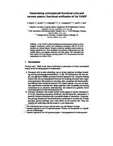
Fig. 1 DMAC generic architecture.
Figure 1 sketches the architecture of a generic DMAC. Roughly speaking, a multichannel DMAC is composed of a set of configuration and status registers, a set of transfer channels, a priority arbiter, and a DMA engine which includes a state machine and a logic block. The configuration registers provide the whole device with the operation settings, including the necessary information to properly perform all the DMA operations. Configuration and status registers can be accessed by the processor through a system bus. Depending on the application, it is possible to activate a microprocessor interrupt that is activated at the end of a DMA channel transfer. Every single channel counts on a particular set of registers that allow the channel to perform independent data transfers. The elements involved in a data transfer are: a source address, a destination address, the number and dimension of the data words to transfer, and finally, the transmission mode selected. Exploiting the DMA arbiter, it is possible to implement different priority modes when different transfers are required at the same time: two of the most commonly adopted are fixed priority and round robin. 3 Proposed approach When tackling embedded system peripherals, devising a stimuli generation technique based on a purely functional approach is a non-trivial task. For instance, setting every channel of a DMAC and checking its correct behaviour in all possible configurations would create a set of stimuli of prohibitive dimensions. Furthermore, once the device is configured, there is also a large number of possibilities for the data and the dimension of the blocks to be transmitted. While a good verification set for the device must be able to thoroughly excite it, it should also
contain a limited number of configuration sets in order to be applicable in real scenarios. We propose a structured methodology for the development of an effective and compact verification program set for system peripherals, based on the analysis of a high-level description of the addressed devices, and providing an operative strategy to verification engineers. The proposed methodology is sketched in figure 2 and aims to reduce the complexity of the produced verification set, guaranteeing at the same time its ability to thoroughly excite the DUT. The first step of this methodology concerns the analysis of the description of the peripheral core, and has two main objectives: firstly, it allows to identify the main elements devoted to the configuration of the device, e.g., the configuration registers; and secondly, it leads to identify the most suitable coverage metrics, depending on the available description of the DUT. Start
Peripheral analysis Identification of shared and unshared resources Configuration generation Generation of verification sequences for shared and unshared resources Logic simulation on the DUT
End
Fig. 2 Proposed methodology flow description.
The second step is devoted to identify shared and unshared resources within the peripheral under test. A shared resource corresponds to some circuitry which is exploited during the management and usage of different channels, while an unshared one participates in the elaboration related to a single channel, only. A shared resource can be either control shared or elaboration shared: Control shared resources are mainly devoted to drive and coordinate the operation of internal peripheral modules; Elaboration shared resources perform specific tasks during data elaboration, and are unique along the data path. These modules may receive or send data to one of a set of internal sub modules (unshared) that implement an identical function. Unshared resources, on the other hand, are mainly involved in the data path as elaboration resources, and
J. Electron Test (2010) xx:xxx-xxx xxx xx.xxxx/xxxxxx-xxx-xxxx-x
are usually present as a set of different modules able to carry out the same function described by the same HDL code, often in order to introduce parallelism. The labeling of resources as shared or unshared can be easily performed on the basis of a high-level description of the DUT. In figure 1, for example, the DMA timing & control module would be labeled as elaboration shared because every channel exploit functionalities performed by it to complete data transfers, while, on the other hand, the priority arbiter would be labeled as control shared, for its control functions. In any case, it is enough to label both modules as shared in order to complete the next steps of the methodology. All channel modules, on the other hand, are clearly unshared. In the third step, all possible configurations of the DUT are subsequently represented by a configuration graph: the main goal of this graph is to provide the methodology with a well organized structure that allows reducing the number of configurations of the device whereas avoiding unnecessary replications. This step provides the user with a reduced set of device configurations that intends to support the creation of the actual verification programs (performed in the fourth step), considering for every program the whole device configuration, as well as special requirements for each configuration path. Conceptually, the configuration graph is a directed graph, whose nodes are grouped in levels, where all nodes in the same level correspond to the same group of configuration bits that control a certain functional characteristic of some device resource; each node in a group represents a value that the group can assume. An arc in the graph from node A to node B that belong to two different levels, exists iff the device can functionally be configured assigning to the groups of configuration bits the values represented by nodes A and B. Several consecutive levels represent all possibilities in the configuration register of a given resource. It is important to notice that a path in the configuration graph can touch only one node in each level, since nodes in each level represent mutually exclusive configurations of an specific device resource. A valid path in the graph starts at the first level and ends in the final one, and represents a legal configuration setting for the device. Figure 3 reports a schematic view of a configuration graph. Reducing the number of considered paths is a priority during stimuli generation, to avoid the explosion of the number of configurations needed and consequently the number of verification programs to run. A first reduction of the configuration graph is performed exploiting information gathered in the previous steps. The maximum number of different configurations available for the device can be
determined by analyzing the configuration registers: usually, the upper bound consists of 2n possibilities, where n is the number of bits contained in all the configuration registers. Not all the 2n configurations, though, are actually useful or valid, and in some cases there are incompatibilities to consider. Impossible configurations do not appear in the configuration graph of the device, but this reduction alone is usually not significant. Labeling modules as shared and unshared is then exploited to further reduce the number of paths needed to cover the entire configuration graph: since sets of unshared modules perform the same functions in the DUT, it is not necessary to excite all configurations of all the shared and unshared modules in a set. Theoretically, to verify all combinations of the DUT configurations, at least each arc of the graph should be covered by one path; experimental evidence, however, suggests that it is sufficient to cover all nodes to obtain a satisfactory coverage of the chosen metrics, as it will be shown in the experimental results section. This constraint alone considerably reduces the number of paths needed to thoroughly excite the device. An intuitive reason to justify experimental data could be the following: consider two independent options with two possible settings each, for example priority (which can be either fixed or rotating) and timing (which can be either normal or compressed). Covering the nodes corresponding to each setting generates two paths, while covering the arcs between them creates four: since the two options are independent, the latter approach originates two useless paths. Let us, for example, refer to Figure 1: as stated above, the priority logic is labeled as shared, while channel modules are unshared. To exhaustively excite the DUT, it is important to stimulate all configurations of the DMA engine, but is not necessary to use every channel in every priority logic configuration.
J. Electron Test (2010) xx:xxx-xxx xxx xx.xxxx/xxxxxx-xxx-xxxx-x
graph information gathered before. Unused configuration
Shared Module
SM[1,2]
SM[3]
UM1[0,1]
Unshared Module 1 UM1[2]
UM2[0,1]
Unshared Module 2 UM2[2]
Bits of a configuration register represented in each level
SM[0]
Fig. 3 A sample path in a configuration graph. On the right, the bits of the configuration register represented in each level. Corresponding nodes in unshared modules are here shown with the same colors.
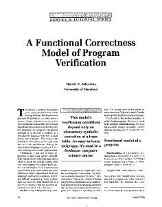
Once the aforementioned operations are carried out, a list of configuration paths must be obtained, following a suitable algorithm to efficiently visit the nodes. The goal of the algorithm is to include each node of the graph in at least one path while keeping the total number of paths as low as possible. In addition, there could be both compulsory paths specified by the verification engineers and prohibited configurations inherent to the DUT. Compulsory paths represent specific corner cases or configurations with great relevance, whose resulting behavior verification engineers desire to check: thus, they are always included in the list of paths, regardless of the algorithm used to visit the nodes. For example, while tackling a DMAC, a verification expert could be interested in enabling a memory-to-memory transfer while enabling the channel 0 address hold. Prohibited configurations are expressed as rules that prevent specific nodes in different levels from being part of the same path, and they must be taken into account each time the algorithm chooses a node included in one of those rules. For example, if the memory-to-memory option is enabled in the command register of a DMAC, the compressed timing option cannot be activated. Figure XX outlines the algorithm exploited to compile the set of configuration paths. In this algorithm, Pt is the set of configuration paths, whereas p is the path under construction. Initially, all nodes in the graph are labeled as unvisited, and every arc is tagged with a 0 value weight. Compulsory paths are firstly created (line 1) exploiting
1 Pt compulsory_paths(graph); 2 If (unvisited_nodes) 3 p null; 4 foreach(level) 5 p choose_node(graph); 6 end; 7 Pt p; 8 endif; Fig. 4 Paths compilation algorithm.
Then, if there are still unvisited nodes in the graph, for every available level in the graph, a node is selected, and then it is included in the current path. In order to correctly select nodes to conform the current path p, the function choose_node(graph) (line 5) evaluates prohibited conditions, and updates nodes and arcs weights. In the case that more than one node is available in the corresponding level, the function chooses one of the possibilities, taking into account graph constraints, and graph information. In the fourth step, the actual test algorithms are defined. Such algorithms are based on the main functionalities of each module that have to be identified: Firstly, shared modules are analyzed. For example, the priority logic module is devoted to actually schedule different channels transfer activity following the configuration settings. However, as a shared device, the priority arbiter performs its handling activities on the complete set of DMA channels regardless of the specific mode of operation of every one; Secondly, unshared modules are considered. For example, the main activity of the hardware involved in every channel module of the DMAC is counting a series of words to transfer, in increasing or decreasing order, bounded by the limits previously defined in the channel internal registers. Two simple cases can thus be devised for a channel module, thoroughly exciting the counter by making it operate in increasing and decreasing order alternatively. This directly descends from the paths derived in the previous step. The verification algorithms defined for unshared modules may require specific restrictions regarding the configuration of the complete device; usually, however, these test algorithms may be flexibly adapted to comply with different global device configurations, as in the case of the DMAC. Real verification programs and external stimuli are hence developed. Each program originates from a path in the graph, and is composed of a configuration part and an operation part. The former directly descends from the configuration described in the path, and is mainly composed of instructions to be run by an
J. Electron Test (2010) xx:xxx-xxx xxx xx.xxxx/xxxxxx-xxx-xxxx-x
available embedded microprocessor to write configuration registers of the addressed system peripheral. The latter part is aimed at activating the device under verification with a suitable set of patterns, which must comply with the selected configuration and must be vast and varied enough to thoroughly excite the components. The operation part can be composed of processor instructions, data to be preloaded in memory, or direct peripheral stimuli. Since each configuration is given in specific terms through the paths derived from the previous step, this task is relatively straightforward and easy to implement, relying on the functional specification of the addressed device.
Memory to memory enable/disable Channel 0 address hold enable/disable Controller enable/disable Timing Normal/Compressed
Control register (shared)
Priority Fixed/Rotating Write Late/Extended dreq active high/low dack active high/low Mode
Illegal/Read/Write/Verify
Initialization Auto / No Auto
Channel 1 (unshared)
Address Inc / Dec Transfer
Unused/Block/Single/Demand
aim is to compute values for the coverage metrics selected in the first step of the workflow, simulating all verification programs created for the paths of the configuration graph. It is important to notice that, if the results did not reach satisfactory levels, a new test case could be easily generated by taking into account previously discarded paths of the configuration graph or inserting compulsory paths that cover the missing elements unveiled by the device simulation. This need, however, never arose during the experiments described in the next sections. 4 Case study In order to assess its effectiveness, the proposed approach has been tested on a benchmark SoC, containing an 8051 compatible IP core [22], a 64 KB data RAM block, a 64 KB program ROM, an 8237compliant DMA controller, and other peripherals with DMA transfer capability (see Figure 4). To connect the processor core to the system bus and provide the DMA module with the proper bus control signals, a simple logic module was interposed between the 8051 external memory port and the data bus. The module includes the required three-state buffers and filters the addresses generated by the processor core, relying on the fact that the employed processor outputs address 0x00000000 when not requiring the control of the data bus. The employed 8237-compliant controller provides four independently programmable transfer channels. DMA requests can be activated via hardware or software. This module allows to control memory-tomemory and peripheral-to-memory data transfers and provides block memory initialization capability. Additionally, it offers static read/write or handshake modes, and includes direct bit set/reset capabilities. Table 1 reports the RT-level description of the DMA controller. The configuration of the DMA controller channels is accomplished by setting each of the bits in the mode register, partially depicted in figure 5.
SoC RAM
P1
P2
P3
P4
Mode Illegal/Read/Write/Verify
Initialization Auto / No Auto
Channel 2 (unshared)
Address Inc / Dec Transfer
Unused/Block/Single/Demand
Fig. 5 Part of a configuration graph, representing the modules of an 8237 compliant DMAC.
In the fifth step, a logic simulation is performed: its
Internal Bus
Processor core
ROM
DMA controller
Fig. 6 Benchmark SoC diagram.
To effectively visit the configuration graph, a pseudorandom algorithm is chosen to leverage nondeterministic selection of the paths, following the indications given in the previous section. Each node is associated with a weight which is initially set to 0 and
J. Electron Test (2010) xx:xxx-xxx xxx xx.xxxx/xxxxxx-xxx-xxxx-x
incremented each time the node becomes part of a path. While creating a path in the configuration graph, a node will be visited if it has the lowest weight value among all nodes in the same level. If two or more nodes in the level share the same value, the node will be chosen randomly with equal probability among those with the lower weight value. The algorithm takes into account both compulsory paths and prohibited configurations. The algorithm was implemented in about 350 lines of Java code, while the configuration files describing available configuration registers, compulsory path and prohibited configurations were written in extended markup language (XML) and, in this case, occupy about 4.73 KBytes of memory. 5 Experimental results Exploiting the described methodology a compact test set for the DMA controller has been generated. Firstly, the configuration registers, such as the command register and mode register, are identified; secondly, coverage metrics are chosen. For the available DMAC model, the most important metrics are statement, condition, and branch coverage. All data about coverage metrics have been gathered at the end of the simulation process performed on Modelsim SE-64 V.6.5c by Mentor Graphics. All the experiments were run on an Intel core2duo processor with 2 Gb RAM. Table 1 DMA controller description at RT-Level DMAC Files Instances VHDL code lines Statements Branches Conditions Fec conditions Expressions Fec expressions Toggle nodes
22 38 3,600 2,144 628 180 250 7 10 746
In the following step, the shared and unshared resources within the controller are labeled and the configuration graph is built. The main shared resource is the DMA engine, followed by the general registers, the internal buses and the priority arbiter. The unshared resources are mainly related to the channel control, such as address registers, word count registers and channel mode registers. By discarding the invalid configurations, we obtained a configuration graph composed of 44 nodes. Considering the shared resources in the DMA description, the data transfer control performed by the DMA priority logic is not directly related to the chosen channel, neither to the address increment or decrement. Thus, each of the transfer modes is linked to only one of
the other resources. This is directly mapped on the configuration graph. Theoretically, by analyzing the device configuration registers, it is possible to identify as many as 232 possible device configurations, which decreases to 28∙[22(22-1)]4 considering the illegal modes. On the other side, exploiting the proposed method, 18 configuration paths are obtained. From each of these paths, a verification procedure is obtained, composed of a configuration part, where the microprocessor writes suitable data in the DMAC registers, and an operation part, where either the processor and the testbench act on the device ports to excite it coherently with the specified configuration. An example of verification procedure derived from a configuration path is described in the following: i. The command register is set with values corresponding to: memory-to-memory disabled; channel 0 address hold disabled; controller enabled; normal timing; rotating priority; late write; dreq active low; dack active high. The register controlling the four channels is set, so that Channel 1 and Channel 4 are configured as: write; auto initialize disabled; address increment; single mode. Channel 2 and Channel 3 are configured as: write; auto initialize disabled; address decrement; demand mode. ii. The memory area where the DMA will write data from the peripheral is cleared. iii. For each channel, the base address register and word counter are initialized. 16 transfers are set for each channel: channels set with address increment will have a base address of 0x0000, while ones with address decrement will have a base address of 0x0010. This combination of values can toggle the first nibble of both the base address register and the word count register. The excitation of the other nibbles of these registers is addressed by other verification programs in the set. iv. A loop is then executed, requesting the transfer on each channel. Control lines are driven by the testbench. In each iteration, several
J. Electron Test (2010) xx:xxx-xxx xxx xx.xxxx/xxxxxx-xxx-xxxx-x
channels are activated at the same time, in order to attest the correctness of the rotating priority schedule. v. Finally, the memory area where data has been written is checked by the processor core. By applying the complete method, a verification set of 18 test programs is obtained, counting about 913 Bytes on the whole; the developing process took about one week, considering the graph construction and analysis and the development of the verification procedures. The whole verification set needs 7,000 clock cycles to be completed. Table 2 reports the coverage results obtained by the application of the complete verification set: all chosen metrics were completely saturated without the need of iterating the process. Some percentages reported do not reach 100% only because of dead code blocks (for example, unreachable conditional branches). Table 2 Coverage results Total Statements Branches Conditions Fec Conditions Expressions Fec Expressions Toggle Nodes
2,144 628 180 250 7 10 746
Covered #
%
2,093 605 162 219 7 10 730
97.62 96.34 90.00 87.60 100.00 100.00 97.86
The results in table 2 show that the proposed method improves the outcome reported in [17], and [18], thanks to the novel techniques introduced in this paper. 6 Conclusions This paper presents a functional based approach to the generation of stimuli for design validation of DMA controllers embedded in SoCs; the generation is backed up by high-level Code Coverage Metrics (CCMs). Experimental results gathered on a sample DMA controller demonstrate the effectiveness of the proposed methodology. Following the proposed approach, a verification engineer can develop in a short time an effective and compact verification set able to saturate verification metrics, relying only on a high-level description of the DUT. Future developments include the application of the proposed methodology to other SoC peripherals and exploiting the principles described to enhance testing techniques, as well as further automation in the generation of instruction sequences and patterns to stimulate the peripheral modules. References
1. Pradhan Dhiraj K., Harris Ian G., “Practical Design Verification”, Cambridge University Press. June 2009, ISBN: 9780521859721 2. Ravotto, D.; Sanchez, E.; Sonza Reorda, M.; Squillero, G.; “Design validation of multithreaded architectures using concurrent threads evolution”, IEEE 22nd Annual Symposium on Integrated Circuits and System Design, 2009. ISBN: 978-1-60558-705-9 3. Bushnell, M.L. and Agrawal, V.D.; “Essentials of Electronic Testing for Digital, Memory, and Mixed-Signal VLSI Circuits”. Springer-Verlag, 2000 4. Thatte, S. and Abraham J.; “Test Generation for Microprocessors”, IEEE Transactions on Computers, vol. 29, n. 6, June 1980, pp. 429-441 5. Paschalis, A.; Gizopoulos, D.; "Effective software-based self-test strategies for on-line periodic testing of embedded processors," IEEE Trans. on CAD of Integrated Circuits and Systems, vol.24, no.1, pp. 88- 99, Jan. 2005 6. Psarakis, M.; Gizopoulos, D.; Sanchez, E.; Sonza-Reorda, M.; "Microprocessor Software-Based Self-Testing", Design & Test of Computers, IEEE , vol.27, no.3, pp.4-19, May-June 2010 doi: 10.1109/MDT.2010.5 7. Cheng, A.; Parashkevov, A. and Lim, C.C.; “A Software Test Program Generator for Verifying System-on-Chip”, 10th IEEE International High Level Design Validation and Test Workshop, 2005, pp. 79-86 8. Shen, J. and Abraham, J.A.; “Native Mode Functional Test Generation for Processors with Applications to Self Test and Design Validation”, Proceedings International Test Conference 1998, pp. 990-999 9. Kranitis, N.; Paschalis, A.; Gizopoulos, D.; Xenoulis, G.; “Software-Based Self-Testing of embedded processors”, IEEE Trans. on Computers, vol 54, n. 4, April 2005, pp 461-475 10. Chen, L.; Ravi, S.; Raghunathan, A.; Dey, S.; “A Scalable Software-Based Self-Test Methodology for Programmable Processors”, Proc. IEEE/ACM Design Automation Conf., pp. 548 – 553, 2003 11. Gurumurthy, S.; Vasudevan, S. and Abraham, J.; “Automated Mapping of Pre-Computed Module-Level Test Sequences to Processor Instructions”, Proc. IEEE Intl. Test Conf. 2005, 12.3, 2005. 12. Psarakis, M.; Gizopoulos, G.; Hatzimihail, M.; Paschalis, A.; Raghunathan, A.; Ravi, S.; “Systematic SoftwareBased Self-Testing for Pipelined Processors”, Proc. IEEE/ACM Design Automation Conf. 2006, pp. 93-398 13. Sosnowski, J.; “Software-based self-testing of microprocessors”, Journal of Systems Architecture, Elsevier, 2005. 14. Bolzani, L.; Sanchez, E.; Schillaci, M.; Sonza Reorda, M.; Squillero, G.; "An Automated Methodology for Cogeneration of Test Blocks for Peripheral Cores," IEEE Int’l On-Line Testing Symposium, 2007, pp. 265-270 15. Apostolakis, A.; Psarakis, M.; Gizopoulos, D.; Paschalis, A.; "Functional Processor-Based Testing of Communication Peripherals in Systems-on-Chip," IEEE Transactions on Very Large Scale Integration (VLSI) Systems, vol. 15, n. 8, Aug. 2007, pp. 971-975 16. Apostolakis, A.; Gizopoulos, D.; Psarakis, M.; Ravotto, D,; Sonza Reorda, M.; “Test Program Generation for Communication Peripherals in Processor-Based SoC Devices," IEEE Design & Test of Computers, vol.26, n.2, March-April 2009, pp.52-63
J. Electron Test (2010) xx:xxx-xxx xxx xx.xxxx/xxxxxx-xxx-xxxx-x 17. Dushina, J.; Benjamin, M.; Geist, D.; “Semi-formal test generation and resolving a temporal abstraction problem in practice: industrial application”, IEEE/ACM Design Automation Conference, 2003, pp. 699-704 18. Grosso, M.; Perez H., W. J.; Ravotto, D.; Sanchez, E.; Sonza Reorda M; Medina-Velasco J., "Functional test generation for DMA controllers", 11th Latin American Test Workshop (LATW 2010), pp.1-6, 28-31 March 2010, doi: 10.1109/LATW.2010.5550334 19. Grosso, M.; Perez H, W.J.; Ravotto, D.; Sanchez, E.; Sonza Reorda, M.; Medina-Velasco, J., "A software-based self-test methodology for system peripherals", 15th IEEE European Test Symposium (ETS’10), pp.195-200, 24-28 May 2010, doi: 10.1109/ETSYM.2010.5512758 20. Goodenough, J.B. and Gerhart, S.L.; “Toward a Theory of Testing: Data Selection Criteria, Current trends in programming methodology”, vol. 2 R. T. Yeh, Ed. Prentice-Hall. Englewood Cliffs, NJ, 1977, pp. 44-79 21. Tasiran, S. and Keutzer, K.; “Coverage metrics for functional validation of hardware designs”, IEEE Design & Test of Computers, vol.18, no.4, Jul/Aug 2001, pp.3645 22. 8051 IP Core circuit description (VHDL): Oregano Systems web site, http://www.oregano.at/eng/ 23. Sonza Reorda, M.; Peng, Z. and Violante, M.; “SystemLevel Test and Validation of Hardware/Software Systems (Springer Series in Advanced Microelectronics)”. Springer-Verlag, New York. 2005