Bambang A. B. Sarif, Mostafa Abd-El-Barr, Sadiq M. Sait , Uthman AI-Saiari. Computer Engineering Department. KFUPM, Dhahran-31261. {sarif, mostafa, sadiq ...
Fuzzified Ant Colony Optimization Algorithm for Efficient Combinational Circuits Synthesis Bambang A. B. Sarif, Mostafa Abd-El-Barr, Sadiq M. Sait ,Uthman AI-Saiari Computer Engineering Department KFUPM, Dhahran-31261 {sarif, mostafa, sadiq, saiarios} @ccse.ktipm.edu.sa Abstract- With the increasing demand for high quality, more efficient, less areaand less power circuits, the problem of logic circuit design has become a multiobjective optimization problem. In this paper, multiobjective optimization of logic circuits based on a fnzzified Ant Colony (ACO) algorithm is presented. The results obtained using the proposed algorithm are compared to those obtained using SIS in terms of area, delay and power for some known circuits. It is shown that the circuits produced by the proposed algorithm are better as compared to those obtained by SIS.
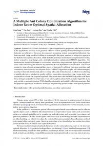
1 Introduction Synthesis of digital circuits can be stated as the process of assembling a collection of logic components to perform a specified function using a target technology. The obtained circuits are optimized for a number of objectives and subject to some constraints. such as area, delay and power. The classical logic synthesis algorithms include the optimization of two quality measures, namely: area and performance [I]. The design objective can be either minimizing the area or maximizing the performance. Optimization can be subject to constraints, such as upper bound on area, as well as upper bounds on performance and lower bound on delay. The possible configurations of a circuit are many. These different feasible implementations of a circuit define its design space. Figure l shows an example design space of a 2bit adder circuit obtained using SIS, considering delay and area of the circuit. The design space consists of a finite set of design points. If the size of the circuit as well as the design objectives are increased, the number of design points could be huge. This will increase the difficulty in finding the optimal structure for a given circuit. Hence, current available techniques divide the circuit design problem into a number of subproblems with lower dimensionality. However, this approach is somehow constrained both by the training and experience of the designer and by the amount of domain specific knowledge available. On the other hand, iterative heuristics can work on a larger space, and through the process of assemble and test, candidate solutions can be built and evaluated. An optimal solution could evolve from this
0-7803-8515-2/04/$20.00 02004 IEEE
45
................. 40
..................
35
.................
30
...................... . .
..
2
4
r
..
6
i
Delay b
8
Figure 1: Design space: areddelay trade-off for a 2-bit adder, process. A number of researchers have worked on evolutionary logic design. Louis [ 2 ] ,Miller [3,4] and Colleo [5],to name a few. They have used different heuristics such as: Genetic Algorithm, Ant Colony and Simulated Evolution. This paper is a continuation of our previous work in [6]. In this paper, a multiobjective evolutionary logic design based on Ant Colony Optimization (ACO) is proposed. Fuzzy logic is used to model the multiobjective cost function. The goal is to find functionally correct circuits optimized in terms of area, delay and power. This paper is organized as follows. Section 1 gives a brief introduction to the problem of evolutionary logic synthesis. Section 2 describes some background material on fuzzy logic. The proposed fuzzy fitness function is given in Section 3. Section 4 describes the proposed approach, Experimental results and comparison are given in Section 5. Finally, conclusion is given in Section 6.
2 Fuzzy Logic Fuzzy Logic was introduced by Lofti A. Zadeh in [71. During the past decades, fuzzy logic has found numerous applications in the field of engineering and control [SI. .In the field of VLSI design, several techniques based on fuzzy logic are reported in the literature 19, IO]. A fuzzy set A of universe of discourse X is defined as A = {(z, P A ( $ ) ) I all 2 E X},where X is a space point and pa(%)is a membership function of z being an element
1317
of A. A membership function ~ A ( z )is a mapping of 2 in A that maps X to the membership space M. The range of the membership function is a subset of the non-negative real numbers whose boundaries are finite. Elements with zero degree of membership are normally not listed. Fuzzy logic establishes approximate truth value of propositions based on linguistic variables and inference rules [ l l ] . A linguistic variable is a variable whose values are words or sentences in natural or artificial language. It is concerned with the use of fuzzy values that captures the meaning of words, human reasoning and decision-making. An example of linguistic variable is circuit’s area. This variable can be expressed by linguistic values like very small, small, average, large and very large circuit, rather than crisp 50 bm’, 75 bm’, and 100 values such as 20 p m Z ,30
pm*. 2.1 Multiobjective Optimization Using Fuzzy Logic Approximate reasoning can be made based on linguistic variables and their values. Rules can be generated based on previous experience. The rules are expressed as If ... Then statements. Connectives such as AND and OR can be used in approximate reasoning to join two or more linguistic values. In optimization problems, the linguistic value used in the consequent part identifies the fuzzy subset of good solutions. Therefore, the result of evaluation of the antecedent part identifies the degree of membership in the fuzzy subset of good solutions according to the fuzzy rule in question. If more than one rule is used to perform decision-making, each rule can be evaluated to generate a numerical value. Then, these numerical values from various evaluations of different rules can be combined to generate a crisp value on a higher level of hierarchy. Consider, for example, the circuit design problem targeting minimization of area, delay, and power consumption. Three linguistic variables area, delay and power introduced. Good solutions can be characterized by the following fuzzy rule. Ifthe circuit has (small area) and (less delay) and (less power consumption) then it is a good solution.
2.2 Ordered Weighted Averaging (OWA) Operator In the traditional fuzzy logic, the minmax operators are used to build the above fuzzy rule. However, it was shown in [ 121 that these operators can lead to undesirable behavior. This behavior has led to the development of other fuzzy operators such as the Ordered Weighted Averaging (OWA) operator. This operator allows easy adjustment of the degree of “AND-ing” and “OR-ing” embedded in the aggregation.
According to [ 131, “OR-like” and “AND-like” OWA for two fuzzy sets A and B are implemented as given in Equations 1 and 2 respectively.
P A ~ Z =)
1 X x m i n ( b a , P g ) + ( l - - X ) x - i ( b ~ + P ~(2) )
where X is a constant parameter in the range [0,1] and represents the degree to which OWA operator resembles a pure “OR’ or pure “AND”respectively.
3 Fuzzy Fitness Function In this section, a fuzzy-based fitness function is formulated. Similar to the weighted sum approach proposed in [6]. the overall fitness of a solution consists of two parts: functional fitness and objective fitness. In this approach, membership functions are used and these membership functions will be aggregated into a single function using a fuzzy operator. Recall to the formulation of functional fitness used in [6], 11. Thus, the membership funcF F lies in the range [0.5, tion for functional fitness is shown in Equation 3. PFF
=
FF
0
if 0.5 5 F F 5 1 otherwise
(3)
Area as Optimization Objective The lower bound on area can be estimated by referring to the VLSI circuit design and logic synthesis principles. For any n-input single-output circuit, the minimum area for the circuit is equal to the area of (n - 1) 2-input gates representing binary tree structure. Since any circuit can be implemented using NAND gates and NAND gates happen to be the smallest among other primitives gates (except NOT gate), then the minimum area is:
min,,,,
= (n - 1) x Area(NAND gate)
In order to guide the search intelligently, a maximum value must be carefully estimated. For this purpose, SIS tools [I] are used to obtain circuits with minimum area. In this context. rugged.script is used to generate the circuits’ netlist files. These files are then fed to our own tool to obtain the estimated value for area, delay and power consumption. The reason behind this is twofold. Firstly, because the delay optimization in SIS does not consider switching delay. Secondly, SIS does not consider power optimization. Since our objective is to obtain circuits with better performance than those obtained using SIS, the estimated values of area, delay and power of circuits obtained using SIS are used as the target values. In the case of area as optimization objectives, the target area is equal to the mea of circuits
1318
obtained using SIS and denoted as tgOreal(see Figure 2). Thus, the membership function for area as optimization objectives is:
circuit generated using SIS with de1ay.scriprexecuted. The membership function for delay as optimization objectives is: 0 5 delay < nindel., mindel,, 5 delay < tgdeloyl otherwise (6)
The shape of the membership function is depicted as the bold line shown in Figure 2.
The shape of the membership function is depicted as bold line shown in Figure 3.
P
P
t
t
mini,lay
tg.iclr,z
tgdelayl
Iwxdelay
Figure 3: Membership function for delay.
Area as Constraint
Delay as Constraint
I n this case, the area of a circuit obtained from SIS is used as target value. For this purpose, the mazareoand tgaFeazshould be defined. The following settings are applied. tgoreoz= kl x tg,,,,l and maz,,,, = kz x tgoreol. kl, kz E 91, 0 < k~ 5 1, kz 2 1. In this case, the membership function is given by:
In this case, the following settings are applied, tgdeIay2 = kl X t g d e l a y l and maZdeloy = 52 X t g d e h y l . k l , kz E 91, 0 < k1 5 1, kz 2 1. In this case, the membership function is given by:
PareLCon
with
=
{:
1 - P2
0 I area < tg.,..l 1 I area < maz,,., otherwise
< tgdelayl 1 5 delay'< mazdeloy otherwise
0 I delay
(7) with
(5)
area - kl mazap...- kl The shape of the membership function is depicted as dashed line shown in Figure 2.
p2 =
Delay as OptimizationObjective The minimum delay (minderay) is estimated as the delay of two-level logic consisting of NAND gates without considering the switching delay. The tgdelnyl is estimated from
delay - 1 mazdelay 1 The shape of the membership function is depicted as dashed line shown in Figure 3. p2 =
-
Power as Optimization Objective The minimum power (minpo,J is estimated as the power consumption of minimum area circuit in which each gate has the least switching activity. It is assumed that for a given truth table, the output of each gate will be '1' only once.
1319
With L = length of truth table,the minimum power consumption (switching activity) can be estimated as follows.
L-1 L2
minpowe7 = 2 . - capacitance(NAND) The tgpOwl is estimated from minimum area circuit generated by SIS. The membership function for power as optimization objectives is: Ppower-obj
with
=
{:
1 -PI
0
5 power < min,,,
minpowI w e ? otherwise
< tgpowl (8)
m e r - min,,,, pl = tg,,, - minpow The shape of the membership function is depicted as bold line shown in Figure 4.
~ - ~as bobjective), j P L ~ ~(delay I ~as ~ - ~ ~ ~ by using ~ , ~ ~ (area constraint) and ppower.con. Then, these three membership functions are aggregated into one unit (the objective fitness) using the OWA operator [12] as follows:
POF
=
x M 4 P a v e u b j 2~ d a i a y - c o nPpower-con) ~
+ (1 - A)
x
+(fiavea.obj
+ ~ d e i o y - c o n+ ~ p o w e T - c o n )
(10) The overall fitness of a cell is formulated as follows.
Fit = W f' P F F
+ (1 - wf)' P O P
(11)
Where W fis the weight for functional fitness. The value of W fmust be large enough in order to have better functionality of the circuit. However, it should not be too large in order to get better quality solutions in terms of design objectives.
4 Proposed Approach
P
t
A circuit is modelled as a matrix M of size n x m. Each cell of the matrix contains a triplet of attributes consisting of the type of gate used and its corresponding inputs, i.e., the row indices of the preceding column (see Figure 5). Input I
tgpavrd
max
Input 2
Gate type
-,
Figure 4 Membership function for power.
Power as Constraint The following settings are applied, tgpowz= kl x tgpOwl and mazpow = kz x tg,,,,, k l , kz E 92, 0 < kl 5 1, kz 2 1. In this case, the membership function is given
XOR
by:
0 6 power < tgpowl 1 6 power < mazpo.,,
7
NAND
9
XNOR
NOR
otherwise
(9) Table 1: Gate ID, gate name and output of the gate. considwith
power - 1 mazpow- 1 The shape of the membership function is depicted as dashed line shown in Figure 4. The type of membership function (as objective or constraint) for each merit determine the goal of the heuristics. For example, optimization or area can be performed
ering input a and b.
p2 =
The values in input 1 and input 2 indicate the row indices from which the current cell is getting its input from. The value of the gate type indicates the type of the gate being assigned to that cells assuming a predetermined set of gate types (see Table I). The input of a gate at position (i, j ) can only be connected to the output of a cell
1320
at (i', ( j
- 1))and a' can be any row index in column ( j - 1).
0.0.0
Begin For 0 < i < iteration Fillingfhe-Matris Ant-Activity Remouing-Unfit.Cells EndFor End
0.4.1
E H 0.34
1.0.0 2.0.0
Algorithm Modified ACO (MACO)
2.3.0
11.
ID)
Figure 6: Example of a circuit and its encoding.
Consider the example shown in Figure 6. Ce11(1,2) whose attribute is (0,3,4) is an AND gate (according to Table l). The first input of the AND gate in this cell is connected to the output of cell(O,l), which is a WIRE, and the second input is connected to the output of celI(2,l). 4.1 Solution Construction
In the beginning, the cells of the matrix A4 are filled with randomly generated attributes. The ants originate from a dummy cell called nest (see Figure 7), and traverse each state (a cell in a column) until it reaches the last column or a cell that has no successor.
......
S(1.m-I)
...... Figure 7: Nest cell and matrix M for ant to be traversed. The selection of edges to traverse is determined by It depends on the pheromone value (T) and the heuristic value ( q ) of the edge. The probability of selecting next cell is formulated below [14]: a stochastic probability function.
The value of a and B imply the preference of the search, whether it depends more on the pheromone value or the heuristic value, respectively. Every newly created cell will be given an initial and small amount of pheromone value. This value will be updated every iteration by the ant. The heuristic value (q)between cell i and j is formulated as follows. (13) 17 = 0.5 + ( P F F ( ~ ) PFF(~))
Figure 8: Modified ACO algorithm for logic design The addition of 0.5 in the calculation of q is meant to normalize the value of q into [0,1]. A decrease in functional fitness means that the value of q is in the range of [0,0.5), while an increase in the functional fitness makes the value of q in the range of (0.5, 11 After the ant finish its tour, pheromone update is performed using the following equation: T ( t ) = (1
- p) * T ( t ) +Fit(t)
(14)
where F i t ( t ) denotes the overall fitness of the solution that the ants built, p i s pheromone evaporation rate. When all ants finish their tours, the solutions provided will be evaluated. All cells that are included in the best solution of the current matrix will be kept. Note that, this solution may not represent the intended function. All unneeded cells will be removed. These empty cells will be filled up again in the next iteration. The ants will then traverse the new matrix and return the best possible solution. If the stopping criteria is not met, the same procedure will be repeated. Figure 8 shows the pseudocode of the approach.
4.2 The Intelligent Ant The Filling and Removing cells procedures in MACO algorithm shown in Figure 8 are performed to handle the limitation of ACO algorithm due to the huge search space of circuit design problem. To further accommodate some improvements the Intelligent Ant is proposed. The original ACO algorithm works on a clearly defined graph where the number of nodes and/or edges is mostly static and the quality of best solution is unknown. On the other hand, the result of evolutionary logic synthesis must be a functionally correct circuit optimized according to the cost function. While traversing the matrix, each ant must seek good solution in terms of circuit's functionality first. Since the length of the tour'is limited by the size of the matrix, the ant should have intelligence to select which part of its tour that provides the best solution in terms of functional fitness. The remaining path will be removed from its memory. Using this approach, the ant will provide better partial
1321
,....
I
~
.......
.
.. .....,.
....... .
. .
. ........
. ... .
..
'
L,---,------------~L L
.
(a)
.
(b)
~
8~
.I
(C)
Figure 9: Example of intelligent ant (a) First solution found, F1 (b) F1 ,F2,and F3 are good solutions. F1 is the best solution (c) Quality of F I can be improved by discarding the path after the arrow sign Table 2: Comparison with SIS in area optimization.
solution in every iteration and that the best solution would emerge at the end of the iterative process. Consider the example shown in Figure 9. The required Boolean function is a 3-bit odd parity circuit. Figure 9 (a) shows one possible solution in the current matrix, denoted as F1 = ( ( X @ Y ) f3 Z) . Z. However, there are 2 other existing solutions in the matrix, namely F2 = ((X@ Y ). 2) XYZ' and F3 = ((X@ Y )'2) XYZ'.Note that F2 and F3 are basically the same function, but since they are found by different ants (hence different path), they are treated as different solutions. From these three solutions, we can easily find that F1 is the best solution. However, the quality of F1 can be improved by discarding some part of its path, since the 3-bit odd parity circuit is F = X f3 Y .2. Hence, the intelligent ant will detect the solution and record the required path only (from input until the arrow sign) shown in Figure 9 (c).
+
+
5.1 Case 1: Area Optimization The rugged.script is used in order to get the area minimized circuits in SIS. The obtained circuits are then mapped for area minimization. Table 4.2 shows the results for area optimization for both techniques. The table shows that for single-output circuits, the highest improvements are obtained in the case of 8-bit and 9-bit odd parity circuits. The parity circuits are best represented using XOR (XNOR) gates. Unfortunately, SIS is unable to perform XOR decomposition. Thus, the parity circuits obtained by SIS requires larger area as compared to the ones obtained using the proposed algorithm. For multiple-output circuits, the improvement in area varies. The highest improvements are observed in the case of 2-bit and 3-bit multiplier circuits. However, the proposed algorithm failed to deliver better circuit in terms of area in the case of add3 circuit, which is the largest circuit used as test case.
5 Experiments and Results
5.2 Case 2: Delay Optimization
In this section. comparison of the results obtained using the proposed algorithm with the results obtained using SIS is presented. However, since SIS does not perform power optimization, the comparison is made only for area and delay optimization.
For delay optimization, the results from SIS are obtained by executing delqscripr mapped for delay minimization. The test cases used are the same circuits used for area optimization.
1322
d
(a)
(b)
Figure 10: 2-bit multiplier circuit (a) Using area optimization (b) Using delay optimization
5.3 Case Study: 2-bit Multiplier Circuit Figure LO shows the result obtained using area and delay optimization for a 2-bit multiplier circuit. As we can see from the figure, in area optimization, the proposed approach prefers the-use of NANb and NOR gates (Figure-10 (a)). This results to circuit with minimum area. However, the longest delay of this circuit is bigger as compared to the one produced using delay minimization (see Figure 10 (b)). This delay is attributed to the load factor caused by fan-out existing in the circuit (see [6] for delay cost function).
6 Conclusion In this paper, an ACO-based evolutionary logic synthesis technique have been proposed. Comparison of the proposed approach with SIS is shown. The proposed approach has shown that it is capable of producing optimized combinational circuits. In addition, the results obtained by the proposed algorithm are better in terms of area, delay and power as compared to SIS.
Acknowledgment: We would like to acknowledge the continued support for our research from King Fahd University of Petroleum & Minerals under project entitled
“Iterative Heuristics for the Design of Combinational Logic Circuits”.
[ l ] E. M. Sentovic, K. J. Singh, L. Lavagno, C. Moon, R. Murgai, A. Saldanha, H. Savoj, P. R. Stephan, R. K. Brayton, and A. L. Sangiovanni-Vincentelli. SIS: A System for Sequential Circuit Synthesis. Technical Report UCB/ERL M9U41, University of California, Berkeley, May 1992. [2] Sushi1 J. Louis. Genetic Algorithms as a Computational Tool for Design. PhD thesis, Department of Computer Science. Indiana University, Aug 1993.
[3] J. E Miller, D. Job, and Vassilev V. K. Principles in the Evolutionary Design of Digital Circuits Part I. Journal ofGenetic Pmgmmming and Evolvable Machines,
-
1(1):8-35,2000.
[4] J. E Miller and I? Thomson. A Developmental Method for Growing Graphs and Circuits. Fifth International Conference on Evolvable Systems: From Biology to Hardware, 2606:93-104, Mar 2003.
1323
[SJ C. A. Coello, A. D. Christiansen, and A. H. Aguirre. Towards Automated Evolutionary Design of Combinational Circuits. Computers and Electrical Engineering, Pergamon Press, 27(1):1-28, Jan. 2001. 161 Bambang A. B. Sarif. A Modified Ant Colony Algorithm for Evolutionary Design of Digital Circuits. IEEE 2003 International Conference on Evolutionary Computation,pages 708-715, December 2003.
[7] L.A. Zadeh. Fuzzy sets. Informtion and Control, 8(3):338-353. June 1965. [8] J. M. Mendel. Fuzzy logic systems for engineering: A tutorial. IEEE Proceeding, 83(3):345-377, Mar. 1995. [9] E. Shragowitz, Jun-Yong Lee, and E. Q . Kang. Appli-
cation of fuzzy logic in computer aided design. IEEE Trans. on Fuzzy Systems, 6(1):163-172, Feb. 1998.
[IO] Sadiq M. Sait and Youssef, H. and J. A. Khan and ElMaleh, A. Fuzzy simulated evolution for power and performance optimization of VLSI placement. Proceedings of International Joint Conference on Neural Nehvorkr, IJCNN 'Ol.,1338 -743, July 2001. L. A. Zadeh. Outline of a new approach to the analysis of complex systems and decision processes. IEEE Transaction Systems Man. Cybern, SMC-3( 1 ) : 2 8 4 , 1973.
[12] Ronald R. Yager. On Ordered Weighted Averaging Aggregation Operators in Multicriteria Decision Making. IEEE Transaction on Systems, MAN, and Cybernetics, 18(1):183-190, Jan 1988. [I31 R. Yager. Second Order Structures in multi-criteria decision making. International Journal ofMan-Machine Studies, pages 3633-570, 1992. [141 M. Dorigo and G. Di Caro. New Ideas in Optimisarion. McGraw Hill, London, UK, 1999.
1324