Conventional proportional-plus-integral (PI) re- gulators have perhaps been the most widely used control method for the speed loop in high-perfor- mance AC ...
ISSN 0005–1144 ATKAAF 44(3–4), 113–122 (2003) Mohamed Rachid Chekkouri, Jordi Català i López, Emiliano Aldabas Rubira, Luis Romeral Martínez
Fuzzy Adaptive Control of an Induction Motor Drive UDK 621.313.333.07 IFAC IA 2.1.4;3.1.1 Original scientific paper
Industrial applications increasingly require electric drives with good position command tracking and load regulation responses. These conditions can only be achieved by adaptive-type control because of the loading conditions, inertias and system parameters all change during the motion. For this paper an Adaptive Speed Controller for AC drives with a very low computational algorithm was developed. The authors propose self-tuning control based on a supervisory fuzzy adaptation. The supervisor continuously monitors the status of the system and changes the Ki parameter of a standard PDF controller to adapt it to the plant’s evolution. The fuzzy logic adaptive strategy was readily implemented and showed very fast learning features and very good tracking and regulation characteristics. The stability of the controller developed was also analysed, and experimental results demonstrated the robustness of the suggested algorithm in contending with varying load and torque disturbance. Key words: adaptive control, adjustable speed drives, fuzzy logic, motion control, variable speed drives
1 INTRODUCTION
Conventional proportional-plus-integral (PI) regulators have perhaps been the most widely used control method for the speed loop in high-performance AC inverter drives. However, other types of simple one-degree-of-freedom controllers such as PDF (Pseudo-Derivative-Feedback) control, have been also used [1]. The proportional term of the PDF controller uses the speed output directly when applied to motion control systems. This structure makes PDF control less responsive to the reference than the PI controller, but allows closed-loop poles of the transfer function be properly placed, thus improving load torque-disturbance rejection capability. The PDF controller is one of the best options for closing the speed loop, providing both satisfactory disturbance rejection and suitable tracking performance in the drive, which are the most important design criteria in motion control systems. Nevertheless, conventional controllers, such as the PDF controllers, require a mathematical model that represents the system under control [2], which is a major limiting factor for systems whose varying dynamics are unknown. For advanced drives, for which the objectives are to achieve both good position command tracking and load regulation, the performance is still not satisfactory under wide operating ranges if the controller parameters are not adaptively tuned according to the variations of the AUTOMATIKA 44(2003) 3–4, 113–122
drive parameters. Tracking and regulation accuracy must not be affected by parameter uncertainties, unknown load variations or external disturbances, and this can only be achieved by adaptive-type control because the loading conditions, inertias and system parameters all change during motion. Adaptive regulators, which take both tracking and regulations capabilities into account and are able to modify their features in order to maintain the desired behaviour of the system, are increasingly beeing used [3, 4]. Over the years, such adaptive speed-control systems have fallen into one of two categories: model reference adaptive control (MRAC) or self-tuning regulators (STR). Self-tuning regulator controllers for motion control that use recursive methods to estimate the parameters of the system have been the most frequent subject of recent analysis in the field [5, 6]. Unfortunately, the complexity of these algorithms is a significant obstacle to the microprocessors used in low- and medium-cost motor drives. Other authors have used fuzzy logic to construct self-tuning non-linear controllers. Robust controllers whose structures are changed continuously by fuzzy logic, depending on the error speed and its time derivative, are presented in [7] and [8]. However, the stability of the whole system is only demonstrated in the continuous s space, neglecting both the current-control loop-time constant and the control digitization. 113
M. R. Chekkouri et al.
Fuzzy Adaptive Control of an Induction Motor Drive
As an alternative, this paper proposes a single and efficient self-tuning speed control that does not use a recursive estimator or observers, but is instead based on a supervisory fuzzy adaptation. The supervisor continuously monitors the status of the system and changes the Ki parameter of an standard PDF controller in order to adapt it to the plant’s evolution according to the dynamics of the system. The adaptive supervision takes place in two stages. The base control changes Ki parameter depending on the speed error amplitude and the auxiliary part drives current Ki value by increasing or decreasing it on a step-by-step basis if error control degrades. The speed regulator was applied to a vector torque control driving a non-linear load, and the whole system was verified by computer simulation. Taking into account control delays and digitization, the asymptotic stability of the adaptive algorithm in a Lyapunov's sense was demonstrated. Experimental results also confirmed the effectiveness of the suggested regulator. 2 SYSTEM CONTROL DESCRIPTION
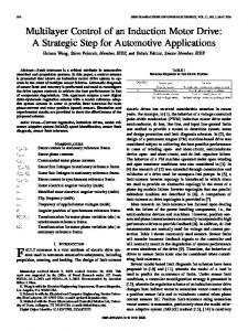
The motion control algorithm shown in Figure 1 is based on the mechatronics assumption of an almost ideal, field-oriented torque controller in a cascade control topology. If it is assumed that proper torque control with high-gain, closed-loop current control was implemented, then the complex dynamics of AC motor torque control can be substituted by a λ delay when modeling the drive and performing simulations. The dynamic model of the mechanical system can be expressed as J dω + B ω + Γ L = Γ , dt
(1)
Γ L = K 0 + K1 ω + K 2 ω2
(2)
Fig. 1 Functional block diagram of proposed self-tuning adaptive controller
where J and B denote the total inertia and viscous friction coefficient of the motor, ω is the rotor speed, and Γ and ΓL are mechanical motor torque and disturbance load torque (2) respectively. K0, K1 and K2 are the coefficients of the Coulomb friction, the viscous friction of the load and the drag force due to turbulent air flow. Table 1 shows the parameters of the plant, which represent a realistic assumption for motor drives. 2.1 Speed Controller
Although the most popular controller for speed control in electrical drives is the classical PI controller, due to its easy implementation and tuning and its suitability, we chose the more sophisticated PDF algorithm, whose time-domain expression is as follows:
Γ ∗ = K i ∫ ( ω∗ − ω) dt − K p ω
(3)
where Ki and Kp are the integral constant and the proportional gain respectively, and (ω* − ω) the speed error e(t). In this design, the proportional gain acts only in the feedback path, thus preventing sudden changes in the speed command going directly to the actuator. In general, PDF controllers provide poorer command-tracking responses than PI controller, but improved disturbance rejection capability [9].
Table 1 Parameters of the plant
114
Parameter
Nominal value
Limit values
J, kg ⋅ m2
Jnom = 0.016
Jnom /5 < J < 5 Jnom
K0, N ⋅ m
K0 nom = 1.6
0 ≤ K0 < 3 K0 nom
K1, N ⋅ ms/rad
K1 nom = 0.03
0 ≤ K1 < 3 K1 nom
K 2, N ⋅ m s2/rad2
K 2 nom = 0.00005
K 2 nom /3 < K 2 < 3 K 2 nom
ωm*, rad/s
ωm nom = 148
− 4 ωm nom < ωm < 4 ωm nom
λ, µs
λ nom = 400
λ nom/3 < λ < 3 λ nom
B, N ⋅ ms/rad
B nom = 0.0015
constant value
AUTOMATIKA 44(2003) 3–4, 113–122
M. R. Chekkouri et al.
Fuzzy Adaptive Control of an Induction Motor Drive
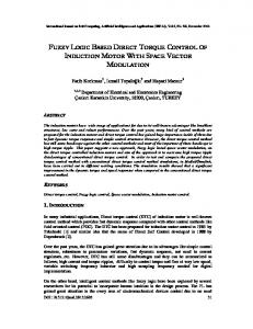
In motor control drives, it is often necessary to provide fast dynamics, which means that the speed controller is often saturated or close to saturation. However, when error decreases the output remains saturated due to integral term, which leads to a large overshoot and a large settling time of the process output. The most common anti-saturation techniques for speed controllers are anti-windup techniques. An anti-windup algorithm was included in the controller, whose final form in s space is shown in Figure 2. Kf is denoted as the tracking time constant, which was set to Kf = Ki /2 following the general rule Ki /4 ≤ Kf ≤ Ki .
closed loop ω(t)/ω*(t), without considering zero-order hold or saturations in order to facilitate the design, is the following: H ( s) =
Ki ω( s) . = ∗ 2 ω ( s) ( J − λK p ) s + ( K 1 + K p − λK i ) s + K i
(5) The closed-loop (5) is a typical second-order transfer function, in which the gain and closed-loop poles are as follows: K=
Ki J − λK p 2
s=−
K1 + K p − λK i K1 + K p − λK i K1 ± − J − λK . − 2 ( J − λK p ) 2 ( ) λ J K p p (6)
The dynamic behaviour of this system can be described in terms of two parameters, ζ and ωn, which are the dumping ratio of the system and the undamped natural frequency
ς= Fig. 2 Speed IP regulator with anti-wind-up technique implementation
K1 + K p − λK i 2 ( J − λK p ) K i
ω2n = 2.2 System tuning considerations
The basic characteristic of the transient response of a closed-loop system is closely related to the location of the closed-loop poles, which are the roots of the characteristic equation. Thus, if this equation is known, poles can be located to force the system response is desired. Despite the fact that the system being analysed is highly complex, several assumptions can be made that help to tune it. Assuming that torque control is perfectly tuned with motor parameters, and current regulations are well implemented, the complex dynamics of ac motor will simplify to a simple torque-commanded model. Moreover, in analysis the response of the outer loop, the inner torque loop can only be considered a delay. Thus, considering λ as the propagation time from the output of the speed controller to the input of the mechanical system, the dynamic model of the rotor speed (1) becomes
Γ ( t − λ) − Γ L = J d ω + Bω. dt
(4)
By applying Taylor’s formulae to Γ (t − λ) in (4), deriving the speed and considering linear approximation of the system by letting Kp ≥ 10 (2 K2 ω) (Kp ≥ 1.89 is large enough to considered as linear even the worst case), the Laplace transform of the AUTOMATIKA 44(2003) 3–4, 113–122
;
Ki . J − λK p
(7)
As is well known, to avoid oscillatory response the following condition must be fulfilled: ζ ≥ 1. After operating in (7), this may be written approximately as follows: K p ≥ − [K1 + λK i ]+ 2 ( J + λK 1 ) K i Ki ≥
2 J − λK p − 2 J 2 − JλK p
(8)
λ2
which gives the relationship between the parameters of the PDF controller. Of the damping ratio values that respond without oscillations, the critically damped response is the fastest. Moreover, the closer the damping ratio is to 1, the lower the overshoot. In spite of the fact that the analysis above cannot be carried out when saturations are considered, it does provide general rules for tuning the system. Thus, the rise time of the system, defined as the time required for the response to rise from 10 % to 90 %, decreases when the value of ωn is high. Hence, the value of Ki should be high if fast tracking is desired (9). Furthermore, high values of Ki lead to low ramp-tracking errors. However, to limit the maximum overshoot, the dumping ratio ζ should not be too small; in this case, expression (8) have to be considered. 115
M. R. Chekkouri et al.
Fuzzy Adaptive Control of an Induction Motor Drive
en =
e( t ) ; ω∗m
en
eni =
d en ; dt
eni ;
eni ⋅ en
IF |en| = Zero
THEN Ki = Large
IF |en| = Medium
THEN Ki = Medium
IF |en| = Large
THEN Ki = Small; m = 3
(18)
(19)
However, there are at least two situations in which FLC does not operate effectively, thus justifying the adaptive block: – when the error is small and does not decreases but increases; – when the error is close to zero and changes slowly or does not change, (i.e., ramp tracking).
Fig. 6 Membership functions for delta adaptation
The fuzzy supervisor was adapted to improve control behaviour under these conditions. A delta factor δ was increased and decreased step by step, which multiplied Ki value while the conditions described above persisted. Therefore, a reinforcement of the output action was introduced. The control of the delta factor depends on the value of one additional input, en e⋅ n, which relates to the control principle en e⋅ n,< 0, and determines the evolution of the error (Figure 6). Delta control also analyses the error evolution in relation to the error amplitude: if an error exists, but it does not change or does it slowly, the Ki value is also incremented by the δ factor. To avoid Ki correction when the error is being reduced correctly, delta adaptation will be disconnected if | e⋅ n| is higher than fifty percent. We also noted that derivative signal is obtained by computation. Generally, the derivative computation is sensitive to the unmodelled vibratory model and measurement noise. Therefore, a small first-order filter was added to the output of this adapter, whose pole does not restrict the system’s frequency response band. The fuzzy tracking block uses the same Mamdani fuzzy reasoning and centroid defuzzification approach as the main fuzzy block. The rules of this auxiliary system are as shown in (20). The block diagram of adaptation is shown in Figure 7. IF |en| = Large AND en e⋅ n = Negative THEN δ = Large
IF |en| = Medium AND en e⋅ n = Negative THEN δ = Small IF |en| = Zero AND en e⋅ n = Negative THEN δ = Nothing
IF en e⋅ n = Positive THEN δ = Large 118
(20)
Fig. 7 Principle of delta adaptation
4.1 Tuning of the Supervisory Fuzzy PDF Control
Plant conditions during tuning procedure are as per the nominal values shown in Table 1. Torque reference was limited to 12 N ⋅ m. Firstly, the standard PDF controller was tuned, and on the basis of this the adaptive fuzzy supervisor was later adjusted. Taking both the critically damped condition (8) and the stability margins (15) into account, the following values were found to ensure stability: Ki = 56 Nm/rad for Kp = 1.89 Nm ⋅ s/rad and Ki Limit ≤ 1350 Nm/rad. The absolute normalized error is assigned to input sets in ten-percent steps, as shown in Figure 5. The output membership functions were chosen to obtain the same Ki parameter as the standard PDF controller at regulation (although lower at tracking); the control action was reduced when it was unnecessary. Delta adaptation starts when error evolution is lower than 50 %, and increases Ki step by step as much as the error increases. To prevent instability in the system, the Ki − δ parameter in Figure 7 is limited to 1 000 Nm/rad. AUTOMATIKA 44(2003) 3–4, 113–122
M. R. Chekkouri et al.
Fuzzy Adaptive Control of an Induction Motor Drive
5 SIMULATION RESULTS
After adjusting the controllers, several simulations were carried out to determine the effectiveness of the proposed supervisor. The sampling frequency for the simulations was 1 kHz, and the standard Integral of Absolute Error (IAE) index was used to compare controllers’ behaviour. The performance specifications were tested in terms of the transient response for different inputs, such as step, ramp and acceleration input and the S-starting curve, which were computed using Matlab-Simulink. Results are obtained for various cases, and changes in the tuning conditions are indicated for each simulation. 5.1 Step input responses
The response of the controllers to a step input does not involve steady-state errors, and they both show very good responses under a wide range of operating conditions. In fact, as expected, the closer the tuning point, the more similar the response. However, the behaviour of the adaptive controller is most improved when the dynamic of the plant increases, due to additional inputs considered for the supervisor. Figure 8 shows the torque and speed response during starting. Note how the adaptive pro-
Fig. 8 Step response of the controllers during starting. J = Jnom /1.5. a) conventional controller; b) adaptive controller
AUTOMATIKA 44(2003) 3–4, 113–122
Fig. 9 Ramp tracking responses: starting details. K1 = K1nom × 2. a) conventional controller; b) adaptive controller
Fig. 10 Parabolic tracking responses: starting details. J = Jnom × 5, K2 = K2nom × 3. a) conventional controller, b) adaptive controller
119
M. R. Chekkouri et al.
Fuzzy Adaptive Control of an Induction Motor Drive
cess increases the control action at start-up, the dynamic error is small, and the drive speed follows the reference speed very closely. 5.2 Ramp input responses
The standard PDF controller is a Type I system, with only one integration on the open-loop transfer function. The steady-state error for a ramp input, which is inversely proportional to the integral constant Ki, cannot be avoided. However, the adaptive controller, which uses both reinforcement action at start-up and delta adaptation later, provides enough control action for a ramp input at starting and quasi-zero actuating error at the steady state to be followed (Figure 9). The steady-state actuating error of the system with parabolic input (acceleration input) is not constant as in a ramp, but tends towards infinite for a standard PDF controller. It can quite reduced with the adaptive controller, as shown in Figure 10. However, for a real starting S curve, which is commonplace in industrial drives, the PDF controller is incapable of following the reference input, whereas the adaptive controller can follow it very closely (Figure 11). The following points can be deduced from the former simulations:
1) The performance of the controller proposed is superb in terms of quick torque response, speed overshoot, speed rise time and recovery time. 2) No steady-state error occurs under dynamic and static load conditions, even following time-varying references. 3) The recovery time is dependent of the adaptive gains of the Ki parameter: the higher the value, the shorter the recovery time, although oscillations may appear. 6 EXPERIMENTAL RESULTS
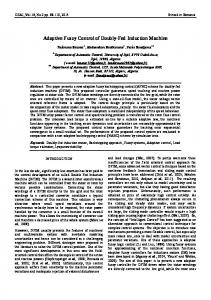
A laboratory prototype was assembled to verify the features of the control system proposed (Figure 12). The whole drive was based on a multiprocessor system composed of a compatible PC as the host and a DSP auxiliary board PC/32C by Blue-Wave Systems inserted in an ISA bus slot. The DSP board included a 32-bit-floating-point TMS320C32 processor running at 50 MHz, which interfaced to the host using 2K×16 DPRAM. The board also includes two high-speed I/O expansions, one for four 16-bit analogue input channels, with a maximum sampling rate per channel of 50 kHz, and another for 32 digital I/O lines, seven of which were used to drive the inverter state, gate controls and enable signal. Three analogue channels were used to close the torque control loop, and another to read the mechanical speed. The task control assignment was distributed between the PC and DSP, so that the first executed algorithms for speed regulation and the second executed algorithms for torque control and space vector modulation to drive the inverter. Moreover, the DSP performed the acquisition and treatment of the analogue plant signals. The DSP also executed the parameter identification algorithms that are needed for vector torque control, though this last loop is not of interest in the discussion of speed regulators carried out in this paper. The inverter, rated for 220/380 VAC, 50 A, used six power insulated-gate bipolar transistors (IGBTs) driven by a PWM-VSI method, with the necessary drives and protections. The two switches of each leg were driven by complementary signals with some deadtime in order to avoid feedthrough fault. The PWM frequency is 10 kHz, and the sampling time of the speed control loop was 1 ms.
Fig. 11 S-starting response. J = Jnom × 5, K2 = K2nom × 3. a) conventional controller, b) adaptive controller
120
The load of the IM drive is a DC machine working as a generator, loaded with a interchangeable set of resistors to vary load torque. The mechanical characteristic of the shaft of the IM can be modelled using expression (2), where K1 is made variable depending on the resistor values. AUTOMATIKA 44(2003) 3–4, 113–122
M. R. Chekkouri et al.
Fuzzy Adaptive Control of an Induction Motor Drive
Fig. 12 PC-DSP based experimental setup for IM drive system
Fig. 13 Experimental responses of the adaptive PDF controller: a) nominal speed reference, b) low speed reference Fig. 14 Experimental responses of the adaptive PDF controller: a) ramp tracking, b) reversal response
A series of tests were carried out in the experimental setup to verify the proposed scheme under different conditions. The responses to the steps at nominal and low speed reference are depicted in Figure 13, which shows that the motor quickly converges to the reference after start-up, confirming the behaviour expected on the basis of previous simulations. AUTOMATIKA 44(2003) 3–4, 113–122
The ramp tracking and speed reversal response for the motor running at medium load torque are shown in Figure 14. Despite several problems in following the reference near the zero speed, which were probably due to the unsuitable mechanical adjustment of the prototype plant, the adaptive con121
M. R. Chekkouri et al.
Fuzzy Adaptive Control of an Induction Motor Drive
troller followed the input command with very few dynamic or static errors. The experimental tests point out the effectiveness of the control scheme, and they prove that the adaptation is well reached. The drive response was quite fast, which demonstrates the suitability of the proposed adaptive method for applications in which fast transient response must be maintained. 7 CONCLUSIONS
The theoretical development and practical implementation of adaptive PDF speed control are presented. It was designed with neither a reference model nor recursive estimations, but by defining a self-tuning procedure by means of fuzzy logic. Variable integral action was incorporated through a supervisory adaptation for improving speed response and controlling robustness with respect to command tracking and load variations, which yielded satisfactory drive performance. The simulations and experimental results validated the effectiveness of the suggested regulator. The system rapidly compensated for any output error caused by either variation in the motor’s parameters or external torque disturbance, including tracking and regulating states. We have demonstrated how a very simple fuzzy adaptive system can replace more expansive adaptive PID algorithms for the speed control of an induction motor drive, maintaining the global stability of the system and strongly damped transient states. ACKNOWLEDGEMENTS The authors are grateful for the financial support received from the Spanish Ministry of Science and Technology as part of the DPI 2001-2213 project.
REFERENCES [1] D. Y. Ohm, Analysis of PID and PDF Compensators for Motion Control Systems. Report on the 1994 IEEE Industry Applications Conference Society Meeting, vol. 3, pp. 1923–1929, Denver, USA, Oct. 1994. [2] S. Weerasooriya, M. A. El-Sharkawi, Adaptive Tracking Control for High Performance dc Drives. IEEE Transaction on Energy Conversion, vol. 4, no. 3, pp 502–508, Sept. 1989. [3] E. Cerruto, A. Consoli, A. Raciti, A. Testa, Fuzzy Adaptive Vector Control of Induction Motors Drives. IEEE Trans. on Power Electronics, vol. 12, no. 2, pp. 1028–1040, Nov. 1997. [4] W. Khan, D. Taylor, Adaptive Control of ac Motor Drives with Inverter Non-linearities. International Journal of Control, vol. 72, pp. 784–798, 1999. [5] M.-F. Tsai, Y.-Y. Tzou, A Transputer-Based Adaptive Speed Controller for AC Induction Motor Drives with Load Torque Estimation. IEEE Transactions on Industry Applications, vol. 33, no. 2, pp. 558–566, March-April 1997. [6] T. J. Kweon, D. S. Hyun, High Performance Speed Control of Electric Machines Using the Kalman Filter and Self-tuning Regulator. Conference Record of the 1998 IEEE Power Electronics Specialist Conference, PESC'98, vol. 1, pp. 280– 286, Fukuoka, Japan, May 1998. [7] A. Suyitno, J. Fujikawa, H. Kobayashi, Y. Dote, Variable-Structured Robust Controller by Fuzzy Logic for Servomotors. IEEE Transactions on Industrial Electronics, vol. 40, pp. 80–88, February 1993. [8] Y. Dote, M. Strefezza, A. Suyitno, Variable-Structured Robust Control by Fuzzy Logic and Stability Analysis for an AC Drive System. Proceedings of the International Conference on Industrial Electronics, Control and Instrumentation, IECON'93, vol. 3, pp. 1962–1967, Maui Hawaii, USA, Nov. 1993. [9] G. Ellis, R. D. Lorenz, Comparison of Motion Control Loops for Industrial Applications. Report on the 1999 IEEE Industry Applications Conference, Thirty-Fourth IAS Annual Meeting, vol. 4, pp. 2599–2605, Phoenix, USA, Oct. 1999. [10] K. Ogata, Modern Control Engineering. Prentice-Hall, Inc., 1970.
Neizrazito adaptivno upravljanje pogonom s asinkronim motorom. Industrijske primjene sve vi{e trebaju elektri~ne pogone s dobrim svojstvima pozicioniranja i regulacije tereta. To se mo`e posti}i jedino adaptivnim na~inom upravljanja, jer se uvjeti tere}enja, momenti inercije kao i ostali parametri sustava mijenjaju tijekom gibanja. U ~lanku je razvijen adaptivni regulator brzine vrtnje za izmjeni~ni pogon s asinkronim motorom koji koristi jednostavan ra~unski algoritam. Autori predla`u samopode{avaju}e upravljanje zasnovano na neizrazitoj adaptaciji s nadzornog nivoa. Nadzorni algoritam neprestano prati stanje sustava i mijenja parametar Ki standardnog PDF regulatora da bi ga adaptirao na promjene stanja u postrojenju. Neizrazita adaptivna strategija realizirana je bez pote{ko}a, sa svojstvom vrlo brzog u~enja te vrlo dobrim svojstvima pozicioniranja i regulacije tereta. Analiza stabilnosti razvijenog regulatora tako|er je napravljena, a eksperimentalni rezultati pokazuju robustnost predlo`enog algoritma pri uvjetima djelovanja poreme}aja u obliku promjenljivog momenta tereta. Klju~ne rije~i: adaptivno upravljanje, pogoni podesive brzine vrtnje, neizrazita logika, upravljanje gibanjem, pogoni promjenljive brzine vrtnje
AUTHORS’ ADDRESSES: Mohamed Rachid Chekkouri, PhD Student @eel.upc.es e-mail: chekkour@ Dr. Jordi Català i Lòpez, Product Engineer Control Techniques Iberia SA @eel.upc.es e-mail: catala@ Dr. Emiliano Aldabas Rubira, Lecturer @eel.upc.es e-mail: aldabas@
122
Dr. Luis Romeral Martínez, Senior Lecturer @eel.upc.es e-mail: romeral@ Electronic Engineering Department Technical University of Catalonia Campus Terrassa, TR2. C/Colom, no. 1 08222. Terrassa, Catalonia, Spain. Phone number: +34 93 739 8194 Fax number: +34 93 739 8016
Received: 2003−11−14
AUTOMATIKA 44(2003) 3–4, 113–122