Fuzzy Logic Based Driving Pattern Recognition for Hybrid Electric Vehicle Energy. Management by. Sushil Kumar. A Thesis Presented in Partial Fulfillment.
Fuzzy Logic Based Driving Pattern Recognition for Hybrid Electric Vehicle Energy Management by Sushil Kumar
A Thesis Presented in Partial Fulfillment of the Requirements for the Degree Master of Science
Approved October 2015 by the Graduate Supervisory Committee: Abdel Ra’ouf Mayyas, Chair A. M. Kannan James Contes
ARIZONA STATE UNIVERSITY December 2015
ABSTRACT For years the automotive industry has been shifting towards hybridization and electrification of conventional powertrains due to increase in fossil fuel cost and environmental impact due heavy emission of Green House Gases (GHG) and various pollutants into atmosphere by combustion engine powered vehicles. Hybrid Electric Vehicles (HEV) have proved to achieve superior fuel economy and reduced emissions. Supervisory control strategies determining the power split among various onboard power sources are evolving with time, providing better fuel economies. With increasing complexity of control systems driving HEV’s, mathematical modeling and simulation tools have become extremely advanced and have derived whole industry into adopting Model Based Design (MBD) and Hardware-in-the-loop (HIL) techniques to validate the performance of HEV systems in real world. This report will present a systematic mythology where MBD techniques are used to develop hybrid powertrain, supervisory control strategies and control systems. To validate the effectiveness of various energy management strategies for HEV energy management in a real world scenario, Conventional rule-based power split strategies are compared against advanced Equivalent Consumption Minimization Strategy (ECMS), in software and HIL environment. Since effective utilization of the fuel reduction potential of a HEV powertrain requires a careful design of the energy management control methodology, an advanced ECMS strategy involving implementation with Fuzzy Logic to reduce computational overload has been proposed. Conventional real-time implementation of ECMS based i
strategy is difficult due to the involvement of heavy computation. Methods like Fuzzy Logic based estimation can be used to reduce this computational overload. Real-time energy management is obtained by adding a Fuzzy Logic based on-thefly algorithm for the estimation of driving profile and adaptive equivalent consumption minimization strategy (A-ECMS) framework. The control strategy is implemented to function without any prior knowledge of the future driving conditions. The idea is to periodically refresh the energy management strategy according to the estimated driving pattern, so that the Battery State of Charge (SOC) is maintained within the boundaries and the equivalent fuel consumption is minimized. The performance of the presented Fuzzy Logic based adaptive control strategy utilizing driving pattern recognition is benchmarked using a Dynamic Programming based global optimization approach.
ii
ACKNOWLEDGMENTS I would first like to express my sincere thanks to professor Abdel Ra’ouf Mayyas for his astounding support and help in this project. He helped me overcome the difficulties I faced during the entire project. His willingness to help me every time I encountered an issue helped me a lot to get through with this project. Without his guidance and profound help, it would not have been possible for me to complete this project. In addition, I would like to thank Professor A.M Kannan, Professor Brad Rogers and James Contes who obliged me with being part of my committee. Secondly, I would like to thank General Motors, the United States Department of Energy, and Argonne National Labs for sponsoring and organizing Advanced Technology Vehicle Competition, EcoCAR 3. Participation in this program has shaped my education and graduate studies. I would also like to express my gratitude for Clemson University International Center for Automotive research, where I was able to perform a crucial experiment which was the backbone of this report. Lastly, I would like to deeply thank my family for supporting me through stress and hardships to complete my studies and accomplish this project. Without their blessings and love, I would not be able to graduate in the stipulated time.
iii
TABLE OF CONTENTS Page LIST OF TABLES..………………………………………...…………………..………viii LIST OF FIGURES………………………………...…………...…….…………..…….. ix CHAPTER 1
2
INTRODUCTION ...................................................................................................... 1 1.1
Background .......................................................................................................... 1
1.2
Introduction To Hybrid Electric Vehicles ............................................................ 2
1.3
Fuel Consumption Reduction In A Hybrid Electric Vehicle ............................... 3
1.4
Motivation For Development Of Supervisory Control Strategies ....................... 4
1.5
Objectives ............................................................................................................. 5
LITERATURE REVIEW ........................................................................................... 7 2.1
Erik Schaltz Article On Electric Vehicle Design And Modeling......................... 7
2.2
King Master’s Thesis On Model-Based Design Of A Plug-In Hev ..................... 7
2.3
Sciarretta And Guzzella Article On Control Of Hev’s ........................................ 8
2.4
Pisu And Rizzoni Article On Supervisory Control Strategies ............................. 9
2.5
Mayyas Et. Al. Article On Vhil............................................................................ 9
2.6
Fang Et.Al. Article On Driving Pattern Recognition For Hev Control.............. 10
iv
CHAPTER 2.7
Page
Zhang Yi And Liu Heping Article On Fuzzy Logic Based Torque Control
Strategy ......................................................................................................................... 11 2.8
Khoucha Et.Al Paper On Optimal Fuzzy Logic Power Sharing Strategy.......... 11
2.8.1 3
Summary of Literature Review ................................................................... 12
METHODOLOGY ................................................................................................... 13 3.1.1
Software Platform ....................................................................................... 13
3.1.2
Plant Modeling ............................................................................................ 14
3.1.3
Driver Subsystem ........................................................................................ 16
3.1.4
Supervisory Controller Model .................................................................... 16
3.1.5
Engine Sub Model....................................................................................... 18
3.1.6
Electric Motor Sub Model .......................................................................... 19
3.1.7
Battery Sub Model ...................................................................................... 21
3.1.8
Passive Powertrain Components ................................................................. 23
3.1.9
Vehicle Dynamics ....................................................................................... 23
3.1.10
Driving Profiles ........................................................................................... 26
3.2
Vhil Simulation Architecture ............................................................................. 29
3.2.1
Ni-Pxi .......................................................................................................... 29
3.2.2
Chassis Dynamometer ................................................................................ 30
v
CHAPTER
4
3.2.3
Hardware Under Test .................................................................................. 30
3.2.4
Simulation Setup ......................................................................................... 32
SUPERVISORY CONTROL STRATEGIES .......................................................... 34 4.1
Rule Based Control Strategy .............................................................................. 34
4.1.1 4.2
4.3
6
Constraints and Thresholds ......................................................................... 35
Equivalent Consumption Minimization Strategy ............................................... 37
4.2.1
5
Page
ECMS Modeling ......................................................................................... 38
Real Time Implementable Ecms Strategy .......................................................... 41
4.3.1
Potential Impact .......................................................................................... 42
4.3.2
Success Rate For Driving Pattern Recognition........................................... 43
4.3.3
Simulation Strategy..................................................................................... 43
4.3.4
Operation..................................................................................................... 45
4.3.5
Simulink Implementation of DPR .............................................................. 46
DISCUSSION AND RESULTS ............................................................................... 47 5.1
Performance Of Rule Based Strategy Against Conventional Vehicle ............... 48
5.2
Performance Of Ecms Strategy Against Conventional Vehicle......................... 51
5.3
Perfromance Of Fuzzy Logic Based Ecms Controller ....................................... 54
CONCLUSION ......................................................................................................... 56
vi
CHAPTER 6.1 7
Page
Future Work ....................................................................................................... 57
REFERENCES ......................................................................................................... 59
vii
LIST OF TABLES Table
Page
1. Vehicle Dynamics Parameters................................................................................... 25 2. Vehicle Specifications ............................................................................................... 31 3. Equivalence Factors .................................................................................................. 44 4. Rule Based vs. Conventional Fuel Economy ............................................................ 51 5. VHiL Fuel Consumption (MPG) ............................................................................... 53 6. Comparison Between VHiL Results ......................................................................... 54 7. Comparison Between ECMS and Fuzzy Logic Based ECMS .................................. 55
viii
LIST OF FIGURES Figure
Page
1. Main Components of Hybrid Electric Vehicle [6] ........................................................ 3 2. Top Level of Vehicle Plant Model.............................................................................. 14 3. Simulink Model for HEV............................................................................................ 15 4. Driver Sub Model ....................................................................................................... 16 5. Generic Supervisory Controller Top Level - Input and Output Signals ..................... 17 6. ICE Efficiency Map .................................................................................................... 18 7. ICE Simulink Model ................................................................................................... 19 8. Electric Motor/Generator Efficiency Map .................................................................. 20 9. Electric Motor Simulink Sub Block ............................................................................ 21 10. Battery Model in Simulink.......................................................................................... 22 11. Forces on a Vehicle [18] ............................................................................................. 24 12. Vehicle Dynamics Block ............................................................................................ 26 13. FUDS Driving Profile [19] ......................................................................................... 27 14. FHDS Drive Cycle [19] .............................................................................................. 28 15. US06 Driving Profile [19] .......................................................................................... 29 16. VHiL Hardware Setup ................................................................................................ 31 17. VHiL Signal Flow ....................................................................................................... 32 18. VHiL Snapshot............................................................................................................ 33 19. Schematic for Rule Based Strategy............................................................................. 36 20. Simulink Implementation of a Rule Based Supervisory Controller ........................... 37
ix
Figure
Page
21. Torque Controller Based on ECMS in Simulink Showing Input and Output Parameters ................................................................................................................... 40 22. Potential of Performance Improvement using ECMS [26] ......................................... 42 23. Success Rate of Real World Driving Cycle Pattern Recognition [12] ....................... 43 24. DPR Framework ......................................................................................................... 44 25. Operation of Proposed Strategy .................................................................................. 45 26. Simulink Implementation Fuzzy Logic based DPR.................................................... 46 27. Rule Based Strategy over FUDS Cycle ...................................................................... 49 28. Rule Based Strategy over FHDS Cycle ...................................................................... 50 29. Rule Based Strategy over US06 Cycle ....................................................................... 50 30. ECMS Control Strategy over FUDS Cycle ................................................................ 52 31. ECMS Control Strategy over FHDS Cycle ................................................................ 52 32. ECMS Control Strategy over US06 Cycle.................................................................. 53 33. Fuzzy Logic Based Strategy Over US06 (Simulation Only) ...................................... 55
x
ABBREVIATIONS HEV: Hybrid Electric Vehicle ICE: Internal Combustion Engine EM: Electric Motor ECMS: Equivalent Consumption Minimization Strategy HIL: Hardware in the Loop VHiL: Vehicle Hardware in the loop SOC: State of Charge FHDS: Federal Highway Driving Schedule FUDS: Federal Urban Driving Schedule EPA: Environmental Protection Agency PID: Proportional Integral Derivative MPG: Miles Per Gallon DPR: Driving Pattern Recognition PTTR: Parallel through the Road ECU: Electronic Control Unit
xi
1 1.1
INTRODUCTION BACKGROUND Since decades, fossil fuels, especially petroleum has been the primary energy
source for transportation. While it has been a better performing alternative than other fuels in past, recent years have witnessed a trend towards using alternative and sustainable sources of energy in transportation sector. The reasons behind this shift are the non-renewable nature of fossil fuel, increasing cost of petroleum products, as well as the environmental threats due to the generation of greenhouse gases (GHG), contributing towards global warming more than ever. In 2012, 1.17 billion barrels of petroleum products were consumed in the US [1], which contributed to a 5.026x10⁹ tons of greenhouse gases released into the atmosphere [2]. The gasoline expenditures for an average U.S. household in 2012 were $2,912, which accounted for nearly 4% of their income [3]. To address the environment protection legislations and to comply with standards like Corporate Average Fuel Economy (CAFÉ) as well as California zero-emission vehicle, there is an increasing pressure on automotive manufacturers to produce more efficient and alternative fuel vehicles. There has been a lot of research going into improve fuel economy of conventional vehicles incorporating Internal Combustion Engines (ICE) in order to produce more efficient vehicles, and we have witnesses numerous technologies like Direct Injection, Turbo Charging, Cylinder Deactivation and Variable Valve Timing. The most important technology, which has surpassed all other technologies in achieving best efficiencies while reducing tailpipe emissions significantly is electrified 1
powertrains. These vehicles are known as Hybrid Electric Vehicles (HEV’s), because of the presence of two onboard power sources, i.e. ICE and Electric Motor (EM). HEV’s will play an important role in coming years towards reducing our dependence on petroleum energy use and improving the environmental degradation due to GHG emissions [4].
1.2
INTRODUCTION TO HYBRID ELECTRIC VEHICLES
HEV’s can be classified into various categories depending on their powertrain
architecture and degree of hybridization. A series hybrid has no mechanical connection between internal combustion engine (ICE) and wheels. The electric motor is responsible for all tractive force, and engine is used to drive a generator, which recharges the batteries. On the other hand, in a parallel hybrid, engine and electric motor are physically connected to the wheels. The size of battery pack determines the degree of hybridization, where a small battery pack corresponds to mild hybrid, and a bigger battery pack means a full hybrid. Generally hybrid vehicle is different than a conventional vehicle in terms of energy storage. Hybrids have two forms of energy onboard, which can be used independently or collectively to propel the vehicle based upon the power demand of the vehicle. Most of the HEV’s have gasoline/diesel as one form of energy, where an ICE is used to convert that energy into mechanical energy. The second form is a bidirectional energy storage device like battery or super capacitor, which can store and release energy upon request. An electric motor is used to convert this stored energy into mechanical energy. The battery size usually determines the level of hybridization, along with the power output of 2
electric motor. Since electric components have higher operational efficiency, i.e. ability to convert stored energy into mechanical power, hence, a higher level of powertrain electrification is a good indicator of higher fuel economy of the vehicle [5].
Figure 1: Main Components of Hybrid Electric Vehicle [6]
1.3
FUEL CONSUMPTION REDUCTION IN A HYBRID ELECTRIC VEHICLE
Fuel Consumption is reduced in a HEV in many forms. A supervisory control algorithm decides the contribution of each energy source in propelling the vehicle in realtime, and the merit of the algorithm decides the effectiveness of hybridization in achieving better fuel economy. The ICE in a conventional powertrain continues to consume fuel even when it is idling, as it has to maintain an idle speed to avoid stalling. Hybrids can eliminate this by shutting off the engine and using electric motor in a start-stop scenario. Regenerative 3
braking is another feature of HEV’s, where the braking energy is not dissipated as heat, and is recaptured using a generator and bidirectional power electronics. The recaptured energy is stored in batteries or capacitors and used whenever needed. Third way to reduce fuel consumption is by ICE downsizing. Conventional vehicles use bigger engines to accommodate for peak power demand, which is a rare event to occur. Most of the times big engines operate at low power, which is an in-efficient region for engine output. HEV’s can make use of more efficient electric motors in conjunction with ICE to meet for high power requests. Hence, HEV’s allow downsized engines in vehicles, which results in fewer emissions and high engine efficiencies. Fuel consumption is further reduced by enabling various operational modes so that the engine can be used in most efficient regions most of the time. It is possible to operate the engine at its most efficient regions most of the time, while meeting the driver demand. This is done by utilizing advanced supervisory controller strategies discussed later in the report [7].
1.4
MOTIVATION FOR DEVELOPMENT OF SUPERVISORY CONTROL STRATEGIES
Hybrid powertrains have a lot of variation in terms of architecture, level of hybridization and vehicle type. With the rise of complex hybrid powertrain systems, there is a need of equally advanced control system in order to meet the customer expectation as well as regulations. In contrast to first generation of HEV’s, now there are numerous individual onboard controllers serving a different purpose related to performance, safety or drivability. High-end Electronic Control Units (ECU’s) are commonplace in vehicles now. Various systems like Fuel Injection, Anti-Lock Braking system (ABS),
4
Transmission Controller and Advanced Driver Assist Systems (ADAS) have replaced the old mechanical/hydraulic control systems and have proved to be more reliable and safe. As the number of onboard ECU’s has grown, the need for a better communication between all the subsystems inside a vehicle has grown as well, as better performance can be achieved when control units are able to share information with each other in real time, and are able to perform tasks more effectively. A Supervisory controller connected with a transmission controller, ABS, Fuel injection and Traction control can perform much better than individual subsystems taking decisions on their own. It facilitates the use of same sensor/actuator for different purposes and making the system more compact. An energy management control strategy is the brain behind the power flow between different energy sources inside a HEV. The effectiveness of a control strategy is a great factor in overall efficiency of the vehicle, and the supervisory controller must be able to make use of all the information available at various on-board ECU’s in order to perform the optimal power split between ICE and electric motor in order to achieve best possible fuel efficiency throughout the driving mission.
1.5
OBJECTIVES
The objective of the research is to implement a Fuzzy Logic based supervisory control strategy to manage the power split between ICE and electric motor inside a parallel hybrid powertrain. The effectiveness of proposed strategy will be compared to conventional rule based strategy and a more advanced “Equivalent Consumption Minimization Strategy (ECMS). The goal is to achieve similar results as compared to ECMS, while reducing the computational overload on supervisory controller. Advanced 5
design tools like model based design and Hardware-in-the-Loop simulation are used to analyze and validate advanced hybrid powertrain control strategies like ECMS. A novel approach to quantify the performance of hybrid control strategy using a chassis dynamometer (VHIL) has been implemented. The research begins with modeling of a hybrid
powertrain
in
a
Parallel-Through-the-Road
(PTTR)
architecture
in
MATLAB/Simulink with rule based power split strategy. The model is modified to incorporate ECMS strategy and the fuel consumption is compared for both the strategies on standard Environmental Protection Agency (EPA) driving schedules, especially Highway (HWFET), City (UDDS) and aggressive (US06). The results are validated by performing VHIL experiment on a conventional powertrain modified to simulate torque assist of an electric motor, hence replicating HEV behavior. The most important aspect of this quantification methodology is that a wide variety of HEV scenario can be implemented on same platform and compared with each other. This technique gives the best comparison of fuel consumption for a conventional vehicle and its hybridized version implementing basic and advanced control strategies.
6
2
2.1
LITERATURE REVIEW
ERIK SCHALTZ ARTICLE ON ELECTRIC VEHICLE DESIGN AND MODELING An article on intechopen.com by Erik Schaltz [8] provides basic understanding of
vehicle modeling and simulation. It explains in detail about following model based design process for electric vehicle modeling and simulation. The same concepts can be easily used for HEV modeling. Modeling of powerflow via different powertrain components like electric motor, battery, transmission, generator, inverters, converters and auxiliary loads has been discussed. Another article in the same book by Livint et.al. [6] Provides general idea of HEV architectures and control. Control strategies for HEV’s have been discussed briefly along with a simplified Simulink model of an HEV powertrain is simulated against a standard UDDS driving profile.
2.2
KING MASTER’S THESIS ON MODEL-BASED DESIGN OF A PLUG-IN HEV Master’s thesis by Jonathan King introduces model based design approach for a
plug-in HEV control strategy for EcoCAR-2 competition. The report provides systematic methodology followed for the architecture selection, control system design, supervisory controller optimization and validation. Energy consumption and Well-to-Wheel (WTW) emission calculation has been used to finalize a series-parallel hybrid powertrain architecture. Advanced verification and validation strategies like Software-in-the-Loop (SIL) and Hardware-in-the-Loop) have been proposed for the finalized powertrain using MATLAB/Simulink software tools and dSPACE HIL simulator. 7
2.3
SCIARRETTA AND GUZZELLA ARTICLE ON CONTROL OF HEV’S Sciarreta and Guzzella authored an article about optimal energy-management
strategies for control of HEV’s [9]. The paper explains that depending upon the effectiveness of control strategy as well as level of hybridization, there is a potential of 10% to 30% improvement in fuel economy over conventional vehicles, which can be realized only by utilizing a sophisticated control system which can optimize the energy flow within the vehicle. It is demonstrated that early energy management controllers utilizing rule-based or heuristic approaches to perform ICE-Electric Motor power split performed well under a limited conditions, and poorly on other scenarios. They have proposed an optimal approach to minimize fuel consumption over a driving mission, where the driving profile is known in advance to the on-board controller. The whole optimization problem is then divided into local optimization problems where local constraints are applied to achieve an optimal power split at given time in order to achieve optimal result for the entire driving mission. Optimization can be achieved by static, numerical or analytical methods. Drawbacks Equivalent Consumption Minimization Strategy (ECMS) has been addressed as it is not possible to have the terrain information always available before the driving mission, as well as computational complexity of optimal control algorithms. Solutions to the problem by using predictive control or adaptive-ECMS have been proposed.
8
2.4
PISU AND RIZZONI ARTICLE ON SUPERVISORY CONTROL STRATEGIES
A paper by Pisu and Rizzoni performing comparative study of supervisory control strategies for HEV’s [10] was a big motivation for this research. In this study, three supervisory control strategies have been compared for a parallel HEV, where no prior knowledge of the drive cycle is required. The approaches considered were rule based control, Adaptive ECMS and Hamiltonian based strategy. All the strategies were analyzed using a model based design approach and the results were compared to a dynamic programming based control strategy. Adaptive ECMS performed best among all the approaches and the fuel consumption was found out to be minimum whereas battery state-of-Charge (SOC) remained within safe boundaries throughout the driving mission.
2.5
MAYYAS ET. AL. ARTICLE ON VHIL
A paper by Mayyas et.al. [11] Provides an excellent platform for verification and validation of supervisory control strategy for a HEV in a HIL environment using a chassis dynamometer and conventional powertrain. The paper gives detailed description of how the design process can be transferred from computer simulations to chassis dynamometer, and system can be quantified in a real world scenario. The paper presents a new methodology for the validation phase of a vehicle development process, called Vehicle hardware-in-the-loop (VHiL), where a complete vehicle comprising of conventional powertrain is set up in a HIL environment over a chassis dynamometer to simulate the road load. The effect of adding a hybrid powertrain to the existing vehicle is 9
carried out in a fast, controllable and cost-effective manner. This technique is very effective in rapid control prototyping of onboard supervisory controllers for HEV’s.
2.6
FANG ET.AL. ARTICLE ON DRIVING PATTERN RECOGNITION FOR HEV CONTROL This paper explains the implementation of Adaptive Hybrid Vehicle Control by
identifying the drive cycle of a vehicle on the run [12]. The on-line driving pattern is recognized by calculating and analyzing the feature vectors and comparing them with a database. The feature vectors comprise of parameters to which a particular type of drive cycle is sensitive. The pattern recognition is utilized to predict the driving profile from a set of profiles like city and highway, and based upon the driving profile, optimal power split among ICE and electric motor is performed. The modeling and simulation is performed in Autonomie software, which is developed by Argonne National Laboratories in order to perform automotive model based design process in a fast and user friendly manner. The paper shows that the success rate for recognition of highway cycles is more than the city cycles, which is further dependent on the feature extraction method used. Based on the size of sample window, the highway cycles can be predicted with 99% success and a fuel consumption improvement of 2.63% has been achieved, which can be improved by incorporating weather and traffic conditions as well.
10
2.7
ZHANG YI AND LIU HEPING ARTICLE ON FUZZY LOGIC BASED TORQUE CONTROL STRATEGY An article by Zheng and Liu present a design method for torque control strategy for
a parallel HEV using Fuzzy Logic [13]. The torque distribution between ICE and Electric Motor is determined by fuzzy criteria instead of hard threshold values as in rule based torque control strategies. The three criteria on which the Fuzzy Logic controller works are: Battery SOC should be controlled within limits; Driver request must be satisfied always and overall efficiency of powertrain components must be optimized throughout the driving mission. Fuzzy rules are then developed which govern the system output depending upon current state of the components and membership functions are created for these fuzzy rules. The controller was developed in Simulink and simulation was performed on various drive cycles, where 9.4% of fuel consumption improvement was claimed over rule based strategies.
2.8
KHOUCHA ET.AL PAPER ON OPTIMAL FUZZY LOGIC POWER SHARING STRATEGY Like previous article, this paper proposes a Fuzzy Logic Controller (FLC) based
on ICE throttle angle and battery SOC. The objective is to maximize fuel economy while reducing emissions and maintaining performance characteristics [14]. The Fuzzy Logic controller is designed to keep the ICE operating at maximum efficiency region as much as possible based on current engine speed and throttle requests. ADVISOR software was used to implement and simulate the controller behavior over European urban (ECE-15) and sub-urban (EUDC) driving profiles. To force the ICE in optimal efficiency region, 11
total required torque is estimated using throttle angle and optimal ICE torque is calculated using torque-speed maps. The optimal torque at which engine will perform most efficiently is demanded from the engine, while rest of the torque is supplemented by the electric motor. ADVISOR simulations show that the Fuzzy Logic Controller was able to force the ICE to operate at more fuel efficient regions most of the times, while maintaining battery SOC within safe limits and fulfilling driver commands all of the time. 2.8.1
Summary of Literature Review The literature review combines the research associated with model based design,
control strategy implementation and supervisory controller validation for HEV’s. This research has provided the basis for this project and has been instrumental in determining the potential of advanced supervisory control strategies like optimal control and Fuzzy Logic for HEV energy management. Starting with the study of modeling hybrid powertrains, implementing basic control strategies and designing advanced supervisory control like ECMS with non-conventional tools like Fuzzy Logic and validation using state-of-the-art VHIL technique has set the path for research and analysis followed in upcoming sections. This study attempts to address various shortcomings experienced in the reviewed literature, where the stimulus for the research being developing and validating a more efficient real-time implementable control strategy for HEV energy management.
12
3
METHODOLOGY
This section will explain the software and hardware framework developed to fulfil the research goals. The modeling approach used to design HEV powertrain, control strategies and the validation using VHiL over a chassis dynamometer are highlighted. 3.1.1
Software Platform
Model Based Design approach was used to develop virtual HEV powertrain architecture using MATLAB/Simulink software platform. MATLAB is a highperformance programming language developed by MathWorks.inc for technical computing [15]. It integrates computation, visualization and programming environment ideal for research purposes. It has an interactive system having an array as basic data element and no dimensioning is required. It is considered as a standard tool for most universities and industries worldwide.
Simulink is a graphical programming tool built on top of MATLAB for modeling, simulating and analyzing dynamical systems. It is fully integrated with MATLAB and other Mathworks© toolboxes and block-sets. It has a capability to connect with hardware for real time testing and can be used to develop a myriad of control systems, signal processing systems, embedded systems, physical systems and dynamical systems. The vehicle models are primarily developed in Simulink and the simulation results are compared to VHiL testing results in order to validate the accuracy of results in a real world scenario. [16]. 13
3.1.2
Plant Modeling
A complete vehicle model incorporating HEV powertrain was developed using a bottom-up approach. A modular structure was followed to simulate entire power flow and reduce complexity, while maintaining the extensibility so that individual components can be added/removed depending upon the architecture of the vehicle. Each powertrain component provides input for next component and accepts feedback simultaneously to maintain closed loop feedback control. This is illustrated in the illustrative top level vehicle model shown below.
Figure 2: Top Level of Vehicle Plant Model
The major components for HEV powertrain are shown in Figure 2 . The principle of operation for each individual component is either decided by the physical equations governing the dynamic response of the component, or by implementing the empirical 14
data provided by the component manufacturer or found in the literature. For example, vehicle dynamics block implements the road-load equation (also known as vehicle glider properties), whereas electric motor and ICE response is simulated using test data obtained from corresponding manufacturers. The model accepts a standard driving profile as input to the driver block, which compares the required speed with current vehicle speed and implements a Proportional Integral Derivative (PID) algorithm to determine the accelerator and brake demand to meet the driving profile speed. The acceleration and brake demand are fed to the supervisory controller block, which implements an algorithm to perform the torque split among ICE and Electric motor depending on the dynamic system state and various threshold values. The calculated torque requests are fed to powertrain block, which consist of ICE, Electric Motor, Transmission, Battery pack and differential blocks. The powertrain block generates a net tractive force at the wheels, which acts as input to vehicle dynamics block, which performs the glider model calculations to calculate vehicle speed for provided tractive force. The top level for developed Simulink vehicle model is show in Figure 3.
Figure 3: Simulink Model for HEV
15
3.1.3
Driver Subsystem
The driver subsystem is designed to replicate a driver’s behavior for a given EPA drive cycle. The Simulink model for driver block takes input from the driving profile preloaded in MATLAB workspace, termed as desired velocity. The vehicle velocity coming out from vehicle dynamics block acts as a feedback input to the driver block. The difference between desired velocity and vehicle velocity is calculated and processed by a PID algorithm, which outputs an accelerator position command (alpha) and brake position command (beta) scaled to 0-1 limit. The vehicle velocity acts as process variable for the PID algorithm, while the vehicle velocity acts as the set point [17]. Tuning the Proportional, Integral and Derivative gains appropriately results in a behavior closely resembling to a driver. For the driver model, the PID gains were set to 0.25, 0.03 and 0 respectively.
Figure 4: Driver Sub Model
3.1.4
Supervisory Controller Model
The controller model is the most versatile part of the entire vehicle, as it can be the simplest or the most complex block depending upon the functionality embedded into its operation. Generally, the controller is responsible for accepting acceleration and brake 16
commands from the driver block and calculate the total torque required from the powertrain to fulfil the driver request. The mechanism to decide the torque spit among the ICE and electric model can vary from very simple to really complex, and this is the main factor behind the effectiveness of the control strategy of a HEV, which in turn is the measure of fuel efficiency of a vehicle. For the study, three types of controller models have been developed and compared: 1. Rule based controller for threshold based power split 2. ECMS based controller 3. Fuzzy Logic based controller implementing ECMS These three controllers have different levels of complexities as rule based logic is simple compared to ECMS.
Figure 5: Generic Supervisory Controller Top Level - Input and Output Signals
17
3.1.5
Engine Sub Model The Engine sub model is an empirical data based model, which has the
functionality of translating requested torque from supervisory controller into output torque at a given speed based upon the torque-speed characteristics of the engine. Based upon the rotating speed of an ICE, its maximum available torque as well as optimal torque for maximum fuel efficiency can be determined. For a HEV, the output torque should be in optimal range as much as possible, which is the motivation behind advanced control strategies which force the ICE to run most efficiently most of the time. ICE mass flow rate data is used to calculate the instantaneous fuel consumed by the engine, which is used for emission and energy consumption analysis.
Figure 6: ICE Efficiency Map
18
Figure 6 shows the torque-speed based efficiency map used for the ICE engine model. We can see that the engine has a peak efficiency of 35% in a very narrow reason, and the controller should be able to confine the ICE operating points near that region, called optimal torque region. Below is the Simulink model for the ICE.
Figure 7: ICE Simulink Model
3.1.6
Electric Motor Sub Model Similar to ICE model, Electric model uses empirical data to simulate the electric
motor behavior. There are equations which can describe the nature of an electric motor, but in order to have faster simulations, an empirical data based modeling approach is followed instead of physical modeling. Furthermore, the motive is to simulate the power flow accurately, hence a high fidelity electric motor model is not very important at this stage. Electric motors have a similar torque-speed based efficiency map, which is replicated in two axes to show the motor as well as generator behavior, as an electric motor can act as a traction motor as well as a generator while regenerative braking is applied. Figure 8 shows the efficiency map for an electric motor for both Motor/Generator behaviors. 19
Figure 8: Electric Motor/Generator Efficiency Map The Simulink model uses this efficiency map to calculate the optimal torque and maximum torque available at a given speed, provided that the battery SOC is sufficient to drive the electric motor safely. This is determined inside the supervisory controller. As evident from the torque curve (Figure 8), Electric Motor offers full torque at low speeds, hence it is an ideal candidate for propelling the vehicle in a start-stop scenario, as ICE cannot provide enough torque at low speeds and operated very in efficiently. This fact is the basis for rule based control strategies, where an electric motor is used to propel the vehicle to a certain speed, after which the ICE takes over and continues to propel the vehicle at higher speeds. Figure 9 shows the Simulink organization and functionality of an Electric Motor sub model.
20
Figure 9: Electric Motor Simulink Sub Block
3.1.7
Battery Sub Model The battery sub model is a simple model designed to replicate real world battery
behavior. Since the thermal aspects of a high voltage battery are not critical for power flow efficiency studies, for this research, thermal modeling was not done and the model simply simulates the Voltage-Current (VI) and battery SOC parameters of a battery pack during a drive cycle. The model accepts the motor power output as an input to determine the current output as well as close circuit voltage of the battery pack. Battery State of Charge (SOC) is determined by dividing total battery capacity from the used battery capacity. To determine the capacity used, battery current is integrated throughout the driving mission. Dividing the battery power by current output gives total closed circuit voltage of battery pack, and open circuit voltage is calculated by multiplying nominal cell voltage by number of cells in series. To differentiate between charging and discharging scenarios, a switch is used which passes charging resistance for negative motor power, and 21
discharging resistance for positive motor power. Similarly to ICE model, the battery model uses empirical data in form of look-up tables to calculate the internal resistance of the battery for different cases.
Figure 10: Battery Model in Simulink
In order to determine the battery current, battery power is divided by internal resistance of the battery, square root of which gives the battery current as shown in equation (1).
=
= i (Current)
(1)
Integrating the current with time will result in consumed battery capacity during the driving mission, which is used to determine the battery SOC by dividing it by total battery capacity.
22
3.1.8
Passive Powertrain Components The components which do not actively participate in powering the vehicle, but are
used to transform power characteristics like torque and rotational speed for smooth operation of the vehicle are termed as passive components. Transmission, Torque Converter, Final differential and wheels come under this category. These components are modeled using basic Simulink blocks where torque and speed input is multiplied or divided with corresponding gear ratios. By taking the overall component efficiency into account, the subsystem can be modeled in a simple and efficient manner. The powertrain block generates total tractive force at the wheels, which is used to calculate resultant velocity of the vehicle using vehicle glider model as discussed in the next section. 3.1.9
Vehicle Dynamics The vehicle dynamics block is the Simulink implementation of road-load equation
for a vehicle. This is also known as glider model for a vehicle, where net tractive force available at the wheels is used to calculate the vehicle speed based upon the different environmental losses acting on the vehicle body. The main factors contributing towards building the resistive forces against the forward movement of a vehicle include rolling resistance of tires, aerodynamic drag due to vehicle’s surface, resistance offered by road grade and initial resistive forces due to rotational components. According to Newton’s second law of motion, vehicle acceleration can be expresses as [18],
=
∑
−∑
23
(2)
Here, V is the vehicle velocity, ∑ ∑
is the net tractive force acting at wheels,
is the net tractive resistance acting due to the factors mentioned previously and is the mass factor multiplied by total mass of the vehicle. These forces can be
visualized using Figure 11.
Figure 11: Forces on a Vehicle [18] The net resistive forces acting on a vehicle can be given as:
1. Rolling Resistance =
∝
(3)
2. Aerodynamic Drag =
1 2
(4)
3. Grade Resistance =
!∝
24
(5)
Here, the different parameters and their experimental values are summarized as; Table 1: Vehicle Dynamics Parameters Parameter
Value
Tire Radius, "
0.3305 m
Vehicle Mass, M
2000 kg
Gravitational Acceleration, g
9.8 m/s2
Air Density,
1.29
Frontal Area,
2.82 m2
Aerodynamic Drag Coefficient,
0.416 ∝ rad
Road grade Coefficient of rolling resistance
The total tractive effort required to move the vehicle is given by, #$%%&
! (
" ) =
−
−
−
(6)
Hence, − %
Where %-
*
− +
− %
is the effective mass of the vehicle and &
!, = %-
∗&
(7)
is the acceleration of the vehicle.
Net tractive required can be expressed as [18], =%
1 + + 2
+ %-
25
∗&
(8)
To model a vehicle dynamics block in Simulink, equation (8) was used. Net tractive force supplied by the powertrain is used to determine the vehicle velocity, which is integrated with respect to time to get distance traveled. The Simulink block diagram for vehicle dynamics is shown in Figure 12.
Figure 12: Vehicle Dynamics Block
3.1.10 Driving Profiles
The main input for the model are the standard dynamometer drive schedules developed by Environmental Protection Agency (EPA) [19]. These drive cycles are a series of data representing velocity of the vehicle at given time on a pre-existing road/terrain. Different countries and authorities have developed various drive cycles to analyze vehicle performance in different road-load conditions and scenarios. Drive cycles are the most reliable and standardized instrument to evaluate various vehicle performance parameters such as fuel consumption, Emissions and acceleration performance. This 26
research uses three main driving profiles which encompass driving scenarios like Highway, City/Urban and aggressive driving. Federal Urban Driving Schedule (FUDS) is a city driving profile, also known as Urban Dynamometer Driving Schedule (UDDS) or City test, as it replicates a generalized scenario of city driving. It is mainly applicable to cars and light duty utility vehicle testing. The total distance for the dive cycle is 7.45 miles with an average speed of 19.59 mph, and it runs for 1369 seconds. This profile incorporates frequent starts and stops, hence imitating city driving. The maximum speed is limited to 55 mph in accordance with maximum city speed limits.
Figure 13: FUDS Driving Profile [19]
The second driving profile used in the research is Federal Highway Driving Schedule (FHDS), alternatively known as highway fuel economy test. This driving schedule replicates a highway driving schedule with a top speed of 60 mph. This profies 27
does not have any stops within the driving mission, however minor accelerations and decelerations are present to account for traffic conditions. The drive cycle runs for 765 seconds covering 10.26 miles at a speed of 48.3 mph.
Figure 14: FHDS Drive Cycle [19]
The final drive cycle used in the research is a supplemental Federal test Procedure (FTP) driving schedule, which is a more aggressive driving schedule consisting of both city and highway scenario with sharp accelerations, decelerations and high speeds. This drive cycle is used to perform high performance analysis on the vehicles. This cycle covers 8.01 miles at an average speed of 48.37 mph for 596 seconds.
28
Figure 15: US06 Driving Profile [19] 3.2
VHIL SIMULATION ARCHITECTURE A real-time target platform is needed for a typical HIL setup in order to execute the
real time simulation with actual hardware (plant). To provide an interface between simulation platform and hardware under test, a I/O controller is needed to process the signals in real time. In this report, NI-PXI-E 6341 real time controller in conjunction with NI-PXI-E 1071 chassis system is used as a platform, whereas a Chevrolet Equinox-2010 crossover SUV (2.4L engine, 182 HP/6700 rpm) on a Renk Labeco chassis dynamometer (48” rollers, 500HP, 4WD) acts as hardware being tested. 3.2.1
Ni-Pxi The PXI-E 6341 is an X series high speed real time controller capable of
supporting 16 Analog inputs and 2 analog outputs in a data acquisition (DAQ) environment. Along with SCB-68A connector block, PXIe-6341 was used to
29
communicate with chassis dynamometer to transmit grade signal and receive velocity signal.
3.2.2
Chassis Dynamometer
A Renk Labeco chassis dynamometer equipped with 48” rollers capable of 500 hp load in a 4WD configuration was used for the experiment. The dynamometer uses four inline eddy-current machines to control roller speed at different modes of operation. Tractive force on the wheels is determined by measuring the turning moment and acceleration of the rollers during running time [11]. The road load equation, as discussed in (7) is used to calculate the roller speed. 3.2.3
Hardware Under Test
The baseline vehicle used for the conducting the experiment is a conventional gasoline ICE-based Chevrolet Equinox, a crossover SUV. The engine has been modeled equivalent to the conventional engine in the real vehicle using a real performance data such efficiency maps from the manufacturer. The hybrid vehicle also has greater mass than the conventional vehicle. The hybrid model developed in the computational software is 286.78 Kg heavier than the conventional SUV due to the inclusion of the new hybrid powertrain components like electric motor, battery, inverter and convertor [20]. The vehicle specifications are described in Table 2.
30
Table 2: Vehicle Specifications Engine
2.4 L DOHC 4–cylinder 182 HP/6700 RPM
DC Motor
Maximum Power: 103 KW Maximum Torque: 180 Nm
NiMH Batteries
Capacity: 23.4 kWhr Number of modules: 44
Automatic Transmission
6 speed, GR: 4.15/2.37/1.56
Vehicle
Curb Weight: 3777 lbs./ 1713.22 Kg
/1.15/0.86/0.68
The experimental setup for the VHiL can be visualized as shown in Figure 16.
Figure 16: VHiL Hardware Setup
31
3.2.4
Simulation Setup
The simulation setup starts with a complete parallel through the road hybrid electric vehicle (PTTR-HEV) model designed in Matlab/Simulink®. To perform the VHiL with real time interface to the hardware (chassis dynamometer in this case) the vehicle model is modified with input-output terminals and compiled into a dynamic library link (*.dll) using Simulation Interface Toolkit (SIT, an add-on to LabView®) for performing Vehicle Hardware in the Loop [11]. SIT is used to interface and facilitate the communication between the executable Simulink version of the plant model and LabView. Executable version of the plant model is then deployed into a real time target (PXI-E 1071 Chassis) used for VHiL purpose which provided with PXI 6341 analog I/O modules to exchange signals between the chassis dynamometer and the plant model. The plant model is designed such that it receives the vehicle actual speed (available as 10 V AO signal at the test rig) and provide the Electric Torque Assist. These the signal flow between PXI and chassis dynamometer is described in the Figure 17.
Figure 17: VHiL Signal Flow
32
Figure 18 shows a snapshot for the VHiL setup for real time road-load adjustment in a
closed loop system.
Figure 18: VHiL Snapshot
33
4
SUPERVISORY CONTROL STRATEGIES
An energy management control strategy is the brain behind the supervisory controller that determine the power split between ICE and electric motor inside a hybrid powertrain. The effectiveness of a control strategy is a great factor in the overall performance of a hybrid vehicle [21]. Control strategy is defined by using various algorithms and constraints which determine the state as well as power output of individual power source so that overall system performs at its maximum efficiency.
4.1
RULE BASED CONTROL STRATEGY The rule based control strategy utilizes simple Boolean rules and threshold values
to control the power distribution between the two power sources. Such control strategy is also referred to as heuristic strategy [9]. This rule based control strategy for parallel through the road architecture is simple and robust. This has been developed on the concepts of Thermostatic power management. The key factor responsible for the power distribution is the Vehicle velocity and Battery SOC. Following constraints decide when to provide battery assisted power and when to keep the engine ON. Almost every production HEV employs a rule based strategy to perform torque split between various on-board power sources in a hybrid powertrain. The reason for this is simplicity of the algorithm and increased computational efficiency of the host embedded controller. Rule based strategies do not require high processing speeds. However, they often suffer with over accumulation or starvation of charge in batteries 34
due to lack of optimal use of electric assist. A better optimal energy management strategies can overcome this problem and provide better performance and result in more fuel savings [22]. 4.1.1
Constraints and Thresholds
Vehicle Velocity and Battery SOC are the threshold and constraint respectively for the system. Based on the driver command and subject to these parameters, the logic controller decides whether to send the requested power demand to motor or to Engine. If the vehicle velocity is below a certain threshold limit and the battery SOC permits the required power to be delivered via the electric motor, the motor delivers the requested power using Battery as the power source. If any of the requirements, i.e. the vehicle velocity and the battery SOC, are unfulfilled, the requested power is provided by the Engine. The schematic in Figure 19 represents a simple logic behind torque controller of the rule based control strategy.
35
Figure 19: Schematic for Rule Based Strategy The torque controller incorporates the rule based control strategy and is responsible for power split between the two sources present on the hybrid electric powertrain. The torque controller consists of switches and Boolean functions to perform the power split. Figure 20 includes a brief outlook of the Rule Based control strategy implemented in Simulink.
36
Figure 20: Simulink Implementation of a Rule Based Supervisory Controller
4.2
EQUIVALENT CONSUMPTION MINIMIZATION STRATEGY
Equivalent Consumption Minimization Strategy was proposed by Paganelli et. Al. [21] with an objective to more effectively optimize the distribution of requested power among the two power sources on the hybrid powertrain by minimizing the equivalent fuel consumption and the pollutant emissions from the vehicle or to achieve a tradeoff between the two [23]. The motivation behind the strategy is that the energy due to regenerative braking is coming originally from the burnt fuel, Hence fuel consumption should be minimized not just for the ICE, but for batteries as well.
ECMS is still a simulation based strategy and it lacks real world qualification because of limitation of available quantified results and testing. Another issue is the processing overhead added to the microprocessor, which monitors many parameters in 37
order to optimally perform the power split among two power sources. To provide more accurate and quantified results for the use of ECMS in a HEV powertrain, VHiL has been performed using ECMS strategy and the results are compared with conventional as well as rule based control strategy.
4.2.1
ECMS Modeling
The main objective of the ECMS based controller is to minimize fuel consumption along a driving mission (global optimization) rather than minimizing the fuel mass-flow rate at each instant of time (local optimization) [9]. The ECMS strategy is a charge sustaining control strategy that reduces the global optimization problem into an instantaneous optimization [24] . This control strategy utilizes a cost function which is dependent on system variables to evaluate the amount of fuel consumed by the engine. An equivalence factor (s) is used to convert change in battery state of charge (SOC) to an equivalent fuel power that must be added to the actual fuel power to attain a charge-sustaining control strategy [9]. Adding up this virtual fuel consumption by the battery to the actual fuel consumption we get the Instantaneous Equivalent fuel consumption as in equation (9). %0-1 2 3 = %0 2 3 + %04 %0-1 2 3 = %0 2 3 +
567
38
84
2 3 2 3. :2;3
(9)
(10)
The total power is the sum of power provided by the Engine 8< and power provided by the battery for propulsion 8=
.
8 2 3 = 8< 2 3 + 8= Here 8=
2 3
(11)
is negative during battery charging.
General Optimization is computed by minimizing the fuel consumption using the following formula: ?@
> %0 2 3
(12)
A
Also the strategy is associated with other constraints like the power produced by the engine8< , maximum energy required by the vehicle8 , ability of battery to meet the power request 8=
and the Δ#C state of the charge of battery.
39
Figure 21: Torque Controller Based on ECMS in Simulink Showing Input and Output Parameters
Figure 21 shows the torque controller developed in Simulink employing ECMS control strategy to perform the power split. In contrast to the rule based controller, ECMS controller accepts 15 input parameters and performs complex calculations to determine the optimal power split among ICE and Electric motor throughout the driving mission.
40
4.3
REAL TIME IMPLEMENTABLE ECMS STRATEGY
Adaptive ECMS (A-ECMS) is an on-the-fly approach to obtain sub-optimal results, where the idea is to periodically refresh the control parameters and update equivalence factor according to the current driving conditions and road load so that SOC is confined within boundaries and fuel consumption is minimized [25]. Another method to obtain sub-optimal real time implementable supervisory control is by using Model predictive Control (MPC) techniques like Driving Pattern Recognition (DPR) where a list of characteristic parameters is used to describe a driving pattern, which in turn allows us to change the control strategy (Parameter Tuning) based upon driving profile [12]. Fuzzy Logic based ECMS control is also useful in achieving near-optimal results with much lesser computational needs [13]. The main constraint to be met by a real-time implementable supervisory control strategy is that the on board controller (ECU) should be able to handle computational requirements on the run. As seen previously, the conventional ECMS algorithm uses 15 parameters for these computations. These parameters are either acquired by various sensors, or computed mathematically to represent the state of all the components in the hybrid powertrain. Processing this amount of information, along with acquiring and generating signals on the run is a very resource intensive approach. To keep cost minimum, automotive industries rely on rule based strategies as they are much simple, reliable and cost effective to implement, the effectiveness however is compromised. Therefore, techniques like Fuzzy Logic and dynamic pattern recognition can be used to
41
reduce computational load while increasing the effectiveness as compared to rule based strategies. 4.3.1
Potential Impact
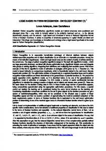
In terms of fuel economy and total energy cost improvement, an optimal control strategy like ECMS provides 7%-15% improvement for trips close to 35 km [9]. The reason for lower magnitude of improvement for longer distances lies in limited energy capacity of battery pack. A smaller battery pack depletes faster and for longer distances, it may not provide enough electric assist and ICE usually ends up for longer durations. Furthermore, driving scenarios like city are more suitable for HEV’s because of availability of recharging in form of frequent regenerative braking.
Figure 22: Potential of Performance Improvement using ECMS [26]
42
4.3.2
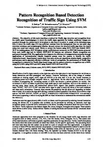
Success Rate for Driving Pattern Recognition To achieve real time Adaptive ECMS comparable results, online terrain preview
techniques need to be implemented in the HEV controller, which will enable the vehicle to adjust the controller characteristics with respect to the road conditions. This can be realized using algorithms like feature vector extraction. However, these type of pattern recognition approaches work better for comparatively large sample sizes and the accuracy varies for different driving scenarios. Feng et. al. [12] have compared various feature extraction methods for different drive cycles and were able to quantify the performance of driving pattern recognition success rate with respect to the sample size.
Figure 23: Success Rate of Real World Driving Cycle Pattern Recognition [12]
4.3.3
Simulation Strategy
In order to develop a pattern recognition algorithm using Simulink, Fuzzy Logic based approached was used where an on-the-fly algorithm was used for the estimation of driving profile. For a sample of 30 seconds, the feature parameters selected to decide the 43
driving mode were mean vehicle speed, Number of stops, stop time, acceleration and deceleration. The number of features have been kept low for simplicity, however more statistical functions like Standard deviation and variance can also be incorporated for more accurate results, for the expense of processing overhead. Figure 24 shows the overall layout of a pattern recognition controller.
Figure 24: DPR Framework The vehicle mode will be used by ECMS controller to estimate equivalence factor, which forms the basis of torque split between ICE and EM. The equivalence factor (s) for urban and highway driving profiles are given in Table 3. This number is used to determine the equivalence fuel corresponding to battery energy as discussed in section 4.2.1.
Table 3: Equivalence Factors FUDS 2.3
Equivalence parameter
44
FHDS 1.9
4.3.4
Operation
The Strategy is designed to function without any prior knowledge of future driving conditions. The energy management strategy is periodically refreshed according to the estimated driving pattern (City/Highway) so that the controller is able to perform similarly to an Adaptive ECMS strategy without having to process a number of variables in real time. This will prevent the processing complexity due to the exclusion of conventional ECMS algorithm and replacing it with a rule based algorithm which is able to replicate the behavior of ECMS to a large extent.
Figure 25: Operation of Proposed Strategy
The battery SOC will be maintained within safe boundaries while minimizing the equivalent fuel consumption for the vehicle.
45
4.3.5
Simulink Implementation of DPR In order to implement the Driving Pattern Recognition in Simulink, the vehicle
velocity is passed through a buffer, where 30 second velocity samples are converted into arrays. These arrays are processed by statistical tools in order to extract five driving profile features, these are: 1. Maximum speed 2. Minimum speed 3. Average Speed 4. Acceleration 5. Stops The Simulink block diagram for DPR is shown in Figure 26
Figure 26: Simulink Implementation Fuzzy Logic based DPR
The extracted feature vector values are used as an input for Fuzzy Logic controller, which determines the vehicle mode based upon the value of different parameters. The mode is then translated into an appropriate equivalence parameter (S
46
parameter) as shown in Table 3. This parameter is used by ECMS controller to perform Adaptive ECMS based torque spit.
5
DISCUSSION AND RESULTS
The research is focused on performing a comparative study between Rule based Control Strategy and Equivalent Consumption Minimization Strategy (ECMS) over parallel through the road hybrid power train architecture. Rule based control strategy is simple in development and implementation. This control strategy is formulated on the concepts of basic thermostatic and load following control strategies. ECMS is an optimal control strategy with primary focus of charge sustenance.
The test vehicle with 2.4L Gasoline engine was tested with the VHiL methodology for the inclusion of a hybrid electric powertrain with a 103 KW electric motor and 30KW NiMH battery pack assisting the 182 hp Gasoline engine in PTTR configuration. The fuel consumed by the vehicle under both the control strategies will determine the effectiveness of respective control strategies. Also the results of hybridized powertrain will be compared with the fuel consumption of conventional powertrain equipped in Equinox and it will help in comprehending the degree of efficiency attained by the hybridization. Performing analysis on different control strategies formulated for the Hybrid Electric Vehicles (HEV) on a real vehicle and developing a road test for the performance analysis is intangible [11]. On the other hand, relying only on the simulation results may 47
not reflect the actual performance of the control strategies due to the fact that simulation are abstract and incorporate a lot of approximation and assumptions. Thus for consolidating the results from the simulation, implementing them over a more reliable test procedures will exhibit more accuracy. The approach of Vehicle Hardware in the loop is the utmost reliable and links the simulations to the road tests. Hence it can be used to predict the performance of these control strategies more accurately.
5.1
PERFORMANCE OF RULE BASED STRATEGY AGAINST CONVENTIONAL VEHICLE The plots shown in the Figure 27 below represent the simulation results for FUDS
drive cycle. The plot represents the relation between the Electric Motor Torque, Battery State of Charge, and Fuel Consumption versus vehicle speed as computed by the simulation for the Rule Based Control Strategy over the entire drive cycle.
Froom the top, the first subplot of the Figure 27 represents the velocity profile for the FUDS drive cycle. The second subplot delineates the inverse relation between the electric motor torque and the SOC of the battery. Since the power source for the electric motor is battery, the positive torque form the electric motor results in SOC drop and negative torque at motor is a result of regeneration and hence increases in the SOC of the battery is observed. Third plot represents the torque at wheels, Fourth represents the fuel consumption between conventional and Rule Based running on the same drive cycle. The final plot represents the comparison between electric motor torque and ICE torque. It is observable 48
that during the negative torque values represented in the plot are for the regeneration. The simulation results projected the MPG of the vehicle.
Figure 27: Rule Based Strategy over FUDS Cycle
Figure 28 and Figure 29 represent the simulation results using the Rule Based Control Strategy for FHDS and US06 Drive cycle. It is important to note that there isn’t much noticeable difference between the conventional and the Rule Based over the FHDS and US06 drive cycles. However another important point to be noticed that since the power requirement for the FHDS is considerably higher, the electric motor hasn’t delivered much power from 50th second till 513th second when power requirement drops and the engine shuts off.
49
Figure 28: Rule Based Strategy over FHDS Cycle
Figure 29: Rule Based Strategy over US06 Cycle
The improvement in fuel economy for a rule based strategy enabled HEV as compared to a conventional vehicle is summarized in Table 4
50
Table 4: Rule Based vs. Conventional Fuel Economy Conventional
Rule Based
FUDS cycle
22 MPG
29.16 MPG
FHDS cycle
32 MPG
35.95 MPG
US06 cycle
20.88 MPG
22.80 MPG
These simulation results represent the decrease in the fuel consumption with increasing Miles per Gallon for a hybrid powertrain with respect to its conventional version. The simulations reflects a 29.8% improvement from conventional using Rule Based Control strategy for FUDS cycle. Clearly looking at the MPG in the above table it is easy to estimate the improvement in the fuel efficiency. Based on the FHDS drive cycle Rule Based control Strategy has 9.91 % improvement than Conventional and according to US06 drive cycle 9.19 % improvement is recorded.
5.2
PERFORMANCE OF ECMS STRATEGY AGAINST CONVENTIONAL VEHICLE
Keeping the format for ECMS plots similar to rule based results, Figure 30, Figure 31 and Figure 32 are from the simulation results with Equivalent Consumption Minimization Strategy. All the figures include different important parameter variation.
51
Figure 30: ECMS Control Strategy over FUDS Cycle
Figure 31: ECMS Control Strategy over FHDS Cycle
52
Table 5: VHiL Fuel Consumption (MPG) Modes VHiL Conventional VHiL Rule Based VHiL ECMS
FUDS 22 29.16 32.71
FHDS 32 35.95 40.7
US06 20.88 22.80 28.5
Table 5 compares the consumption of gasoline in liters for three different types of testing setup. The fuel consumption for a conventional vehicle on the chassis dynamometer is compared with fuel consumption of an equivalent HEV implementing Rule based supervisory control strategy and ECMS strategy over VHiL platform. ECMS shows tremendous reduction in fuel consumption when compared to the two other VHiL setups.
Figure 32: ECMS Control Strategy over US06 Cycle Using ECMS Control strategy the fuel consumption stated by the simulation results for city is 32.71 miles per Gallon, whereas the MPG reported by simulating the Rule Based Control Strategy for city is 29.16 MPG. The MPG reported by the conventional 53
vehicle is just 22 MPG. As looking to the table of fuel consumption it is easy to compare the efficiency of ECMS control strategy with the rule based for the Hybrid vehicles. Under the same powertrain ECMS control strategy is much more efficient than the rule based and has following percentage improvement:
Table 6: Comparison Between VHiL Results Drive Cycle
ECMS Efficiency improvement over Rule Based 12.17 % 13.19 % 24.78 %
FUDS FHDS US06
The results shows the improvement in the performance of the electric assist and the significant fuel savings due to hybridization. Successful implementation of VHiL approach reflects the impact of the new pipe lines created between the pure simulation generated during the concept/design phase and the validation phase for a complete vehicle system.
5.3
PERFROMANCE OF FUZZY LOGIC BASED ECMS CONTROLLER
The modified ECMS controller with Fuzzy Logic based DPR strategy was implemented in Simulink and the simulation was performed over US06 drive cycle, as the drive cycle consists of both city and highway driving scenarios in an aggressive manner. The simulation result shows are comparable to the results achieved by ECMS for US06 cycle, however the driving mode prediction algorithm needs to be more refined, as success rate for implementing the pattern recognition is less than anticipated. 54
Figure 33: Fuzzy Logic Based Strategy Over US06 (Simulation Only)
The simulation result shows a slight improvement in fuel economy for Fuzzy Logic based ECMS controller, as the controller can optimize the equivalence factor in real time and based upon the driving conditions the Engine torque and Motor torque can be optimized more accurately. The fuel consumption has been found to be 6% less as compared to VHiL validation of ECMS strategy. However, since the fuel economy results for Fuzzy Logic based strategy are purely simulation based, a slight difference in real world testing is anticipated. Table 7: Comparison Between ECMS and Fuzzy Logic Based ECMS Modes VHiL ECMS Fuzzy Logic ECMS (Simulation Only)
FUDS 32.71 32.33
FHDS 40.7 40.4
US06 28.5 30.21
However, for pure city and highway drive cycles like FUDS and FHDS, there is no significant improvement in fuel economy as there is no optimization with respect to road 55
conditions, as they do not change throughout the mission and the equivalence factor remains unchanged. However, the main advantage of using Fuzzy Logic based predictive strategy to implement ECMS lies in the execution of algorithm using lesser computational resources as compared to approaches like dynamic programming. Hence, average supervisory controllers can be used to implement advanced control strategies with comparable results.
6
CONCLUSION
This work implements a relatively new approach for automotive systems validation called Vehicle hardware In-the-loop “VHiL”, where vehicle test bed is utilized as a platform for HIL simulation. The VHiL approach is utilized to validate the inclusion of a hybrid electric power train into an existing conventional ICE-based platform early in the design process (i.e. concept/design phases). The hybrid electric power train modules are simulated, whereas the rest of the vehicle is real. The 250 HP conventional ICE-based power train of SUV was tested on a 4WD 500 HP chassis dynamometer for the inclusion of PTT hybrid electric power train with an efficient RB energy management strategy. The results shows the improvement in the performance of the electric assist and the significant fuel savings due to hybridization. Upon successful implementation of VHiL, this research performs a comparative study between Rule based Control Strategy and Equivalent Consumption Minimization Strategy (ECMS) over parallel through the road hybrid power train PTT-HEV configuration. The fuel consumed by the vehicle under both the control strategies assist 56
evaluation the effectiveness of respective control strategies. Also the results of hybridized powertrain are compared with the fuel consumption of conventional powertrain equipped in Equinox and will help us comprehend the degree of efficiency attained by the hybridization To address the concerns regarding real time implementation capabilities of ECMS strategies due to limited processing power of on-board ECU’s and high complexity algorithms involved in ECMS, A new methodology involving the use of Fuzzy Logic controller to estimate the Driving Pattern and scaling the torque split between ICE and electric motor was proposed. The controller uses basic features of vehicle speed like Maximum speed, stops, acceleration, average speed and deceleration to estimate the operational mode, which is used to determine the overall power output form the components. The approach has been found out to be less complex and equivalent in efficiency as compared to ECMS.
6.1
FUTURE WORK
There is a lot of scope in predictive strategies for HEV energy management. The first step in the research would be a VHiL testing of Fuzzy Logic based Adaptive ECMS strategy, which will provide a validation of the proposed methodology. Furthermore, advanced feature detection methods should be used in order to predict the driving mode in a better way [20]. Also, advanced energy management strategies involving future information like Global Positioning System (GPS), traffic signal data and traffic 57
congestion should be implemented in pattern detection in order to optimize the fuel consumption in a more efficient manner [26].
58
REFERENCES
[1] U. E. I. Administration, "Petroleum & Other Liquids," www.eia.gov, 2012. [2] U. E. P. Agency, "Inventory of U.S. Greenhouse Gas Emissions and Sinks," www.epa.gov, 1990-2013. [3] U. E. I. Administration, "Today In Energy," www.eia.gov, 2013. [4] U. E. P. Agency, "Green Vehicle Guide," www.epa.gov, 2015. [5] U. D. o. Energy, "Energy Efficiency & Renewable Energy - How Hybrids Work," www.fueleconomy.gov, 2015. [6] G. Livint, V. Horga, M. Ratoi and M. Albu, "Control of Hybrid Electricla Vehicles," in Electric Vehicles - Modelling and SImulations, InTech, 2011, pp. 41-66. [7] J. C. King, "Model-Based Design of a Plug-In Hybrid Vehicle Control Strategy," Virginia Polytechnic Institute and State University, Blacksburg, VA, 2012. [8] E. Schaltz, "Electrical Vehicle Design and Modeling," in Electric Vehicles Modelling and Simulation, InTech, 2011, pp. 1-25. [9] A. Sciarretta and L. Guzzella, "Control of Hybrid Electric Vehicles - Optimal Energy-Management Strategies," IEEE Control Systems Magazine, pp. 60-70, 2007. [10] P. Pisu and G. Rizzoni, "A Comparitive Study of Supervisory Control Strategies for Hybrid Electric Vehicles," IEEE Transactions on Control Systems Technology, pp. 506-519, 2007. [11] A. R. Mayyas, R. Prucka, I. Haque and P. Pisu, "Vehicle Hardware in-the Loop Simulation for an integration of advanced hybrid electric powertrain," International Journal of Electric and Hybrid Vehicles, pp. 215-233, 2013. [12] L. Feng, W. Liu and B. Chen, "Driving Pattern Recognition for Adaptive Hybrid Vehicle Control," SAE International, pp. 169-180, 2012. [13] Z. Yi and H. Liu, "Fuzzy Logic Torque Control Strategy for Parallel Hybrid Electric Vehicles," in Eighth International Conference on Fuzzy Systems and Knowledge Discovery, 2011. [14] F. Khoucha, M. BenBouzid and A. Kheloui, "An optimal Fuzzy Logic Power Sharing Strategy for Parallel Hybrid Electric Vehicles," University of Brest. 59
[15] T. M. Inc., "MATLAB R2014a," 2015. [Online]. Available: http://www.mathworks.com/products/matlab. [16] T. M. Inc., "Simulink," MathWorks, 2015. [Online]. Available: http://www.mathworks.com/products/simulink. [17] C. S. Inc., "PID for Dummies," Control Solutions Inc., [Online]. Available: http://www.csimn.com/CSI_pages/PIDforDummies.html. [Accessed 2015]. [18] R. N. Jazar, Vehicle Dynamics - Theory and Operation, Springer, 2014. [19] U. S. E. P. Agency, "Dynamometer Drive Schedules," US EPA, [Online]. Available: http://www.epa.gov/nvfel/testing/dynamometer.htm. [Accessed 2015]. [20] C. C. Lin, H. Peng, J. W. Grizzle and M. J. Kang, "Power management strategy for a parallel hybrid electric truck," IEEE Transactions on Control Systems Technology, vol. 11, no. 6, pp. 839-849, 2013. [21] G. Paganelli, G. Ercole, A. Brahma, Y. Guezennec and G. Rizzoni, "General supervisory control policy for the energy optimization of charge-sustaining hybrid electric vehicles," JSAE review, vol. 22, no. 4, pp. 511-518, 2001. [22] L. Guzella and A. Sciarreta, Vehicle Propulsion Systems - Introduction to Modeling and Optimization, Springer, 2013. [23] L. Serrao, S. Onori and G. Rizzoni, "ECMS as a realization of Pontrygin's Minimum Principle for HEV control," in American Control Conference, 2009. [24] L. Xu, G. Cao, F. Yang, L. Lu and M. Ouyang, "Equivalent COnsumption Minimization strategy of series hybrid city buses," State Key Lab of Automotive Safety and Energy, Tsinghua University, China. [25] C. Mursado, G. Rizzoni and B. Staccia, "A-ECMS: An Adaptive Algorithm for Hybrid Electric Vehicle Energy Management," in 44th IEEE Conference on Decision and Control, 2005. [26] C. Zhang and A. Vahidi, "Real-Time Optimal Control of Plug-in Hybrid Vehicles with Trip Preview," in American Control Conference, 2010.
60