Department of Computer Science, National Institute of Technology, Calicut, Kerala, India ... An image I(x,y) is composed of reflectance component R(x,y) ... Please cite this article in press as: Sasi RK, Govindan VK, Fuzzy split and merge for shadow detection, ... mean value of A and B planes of an LAB image is proposed.
Egyptian Informatics Journal (2014) xxx, xxx–xxx
Cairo University
Egyptian Informatics Journal www.elsevier.com/locate/eij www.sciencedirect.com
Fuzzy split and merge for shadow detection Remya K. Sasi *, V.K. Govindan Department of Computer Science, National Institute of Technology, Calicut, Kerala, India Received 20 May 2014; revised 12 September 2014; accepted 30 November 2014
KEYWORDS Shadow detection; Split and merge; Fuzzy predicate; ANFIS
Abstract Presence of shadow in an image often causes problems in computer vision applications such as object recognition and image segmentation. This paper proposes a method to detect the shadow from a single image using fuzzy split and merge approach. Split and merge is a classical algorithm used in image segmentation. Predicate function in the classical approach is replaced by a Fuzzy predicate in the proposed approach. The method follows a top down approach of recursively splitting an image into homogeneous quadtree blocks, followed by a bottom up approach by merging adjacent unique regions. The method has been compared with previous approaches and found to be better in performance in terms of accuracy. � 2014 Production and hosting by Elsevier B.V. on behalf of Faculty of Computers and Information, Cairo University.
1. Introduction Shadows are formed when light from a source is partially or totally blocked. It is difficult to catch images and videos free from shadows. Hence, the only possibility is to remove once it is caught. If we ignore the existence of shadows in images it may introduce serious issues such as alternation of object shape, object merging and object lose in various visual processing applications such as image segmentation, scene interpretation, classification, and object tracking. Hence, Shadow detection and removal is considered as a preprocessing step in various image processing applications such as automated * Corresponding author. Peer review under responsibility of Faculty of Computers and Information, Cairo University.
driving [1], surveillance system [2], satellite imaging [3] and medical imaging modalities [4]. 2. Background An image I(x, y) is composed of reflectance component R(x, y) and the illumination component L(x, y) as follows [5]: Ik ðx; yÞ ¼ Rk ðx; yÞ � Lk ðx; yÞ
where k C � {R, G, B} and ‘‘Æ’’ denotes pixel-wise multiplication. Shadow regions are formed by reduction in the illumination component, resulting in changes of image intensities by multiplicative scalars Ck(x, y). Thus, (1) can be rewritten as Ik ðx; yÞ ¼ Rk ðx; yÞ � Lk ðx; yÞ � Ck ðx; yÞ
ð2Þ
Taking the logarithm on both sides of Eq. (2) we obtain Ik ðx; yÞ ¼ Rk ðx; yÞ þ Lk ðx; yÞ þ Ck ðx; yÞ
Production and hosting by Elsevier
ð1Þ
ð3Þ
where I, R, L and C are the logarithms of I, R, L and C, respectively. Thus, in the log domain, a shadow implies an
http://dx.doi.org/10.1016/j.eij.2014.11.003 1110-8665 � 2014 Production and hosting by Elsevier B.V. on behalf of Faculty of Computers and Information, Cairo University. Please cite this article in press as: Sasi RK, Govindan VK, Fuzzy split and merge for shadow detection, Egyptian Informatics J (2014), http://dx.doi.org/10.1016/ j.eij.2014.11.003
2 additive change in intensities. Many works have been reported in the literature by trying to reduce the additive shadow component. However, finding the regions affected by shadow needs intelligent shadow segmentation methods, and hence, it is not an easy task. Self-shading, inter-reflection, non-uniform shadow, geometry of the object casting shadow, and the artifacts involved in image capturing make the process of shadow detection more complicated. The rest of the paper is organized as follows: A brief review of some of the important work in shadow detection and removal is carried out in Section 3. The proposed fuzzy split and merge approach and ANFIS architecture are presented in Sections 4 and 5 respectively. Implementation details and experimental results are given in Sections 6 and 7. Finally the paper is concluded in Section 7. 3. Related works A number of shadow detection algorithms have been proposed in the literature for still images, satellite images and videos. Most of the works reported in the area of moving shadow detection are specific to a particular domain such as traffic monitoring [1] and video surveillance systems [2]. Hence, they are not suitable for general application. Shadow detection from still images involves methodologies to detect shadows generated by nonpoint light sources called soft shadow [6] and point light sources called hard shadow [1]. A general method that can be commonly applied to all categories has not been devised till now. State of the art methods that use multiple images [7], video frames [2,8] or methods that allow user intervention [9,10] have given impressive results, but detecting shadows accurately from a single indoor or outdoor image having various geometrical features and illumination constraints remains an open problem. This is because the appearances and shapes of indoor and outdoor shadows depend on several factors such as the color, direction, size of the illuminants (sun, sky, clouds), geometry of the objects that are casting the shadows and the shape and material properties of objects onto which the shadows are cast. This section gives a brief overview of various shadow detection approaches reported in still images. Zhu et al. [9] proposed a learning based method to detect the shadows in single monochromatic image using a shadow invariant, shadow variant and near-black features. This method is based on boosted decision tree classifier which is integrated into a Conditional Random Field (CRF). To make it possible to learn the CRF parameters, they use a Markov Random Field (MRF) model for labeling. An approach to extract shadows from an image using the information supplied by the user is proposed in [10]. This method requires user help as the shadow, non-shadow and background regions are interactively specified by the user. Ruiqi et al. [11] proposed a method for detecting shadows using a relational graph of paired regions. But, this method cannot differentiate between shading differences due to surface orientation changes and due to cast shadows. Also, shadow detection fails in case of multiple light sources. Fuzzy based approach of shadow detection is proposed by Muthukumar et al. in [12]. This method is based on tricolor attenuation model (TAM), and considers shadow regions as special kind of image degradation. Shadow edge detection is
R.K. Sasi, V.K. Govindan conducted based on the color constancy. A fuzzy c-means algorithm is adopted for segmentation. In [13], trained decision tree classifier is used to detect ground shadow edges in outdoor images. The shadow edges are then grouped by a Conditional Random Field (CRF) based optimization. This method focuses on shadows cast by objects onto the ground plane. Shadow detection method that works on the basis of the mean value of A and B planes of an LAB image is proposed by Murali and Govindan in [14]. Combining the values from L and B channels, the pixels with values less than a threshold are identified as shadow pixels, and others as non-shadow pixels. The method works well only for images whose yellow to blue ratio is maintained within a range. Finlayson et al. [15] proposed a method to locate the shadows by generating an illumination-invariant image, in which the shadows do not appear. The illumination-invariant image is used with the original color image to locate the shadow edges. This method requires images acquired using a calibrated camera to get better result. A physical model of shadow based on the properties of shadow under the sun and sky is proposed in [16]. This method cannot characterize the indoor shadows. Most of the works reported on shadow detection need multiple images, user interaction/inputs and calibrated camera. Shadow detection and removal from a single image, having various geometrical features and textures exhibiting different reflection parameters remains an extremely challenging problem. 4. Proposed approach This paper proposes a split and merge approach that uses a fuzzy predicate for shadow detection from a single image. As a first step we perform a top down approach of splitting an image into four quadtree blocks and produce a sparse representation of the image in tree form. Then a Fuzzy predicate is used to check for any adjacent homogeneous region that can be merged among the quadtree blocks. Adjacent homogeneous regions are merged and the splitting merging process is repeated recursively. Fuzzy predicate is trained using ANFIS. 4.1. Fuzzy split and merge Classical split and merge is a famous algorithm developed by Horowitz and Pavlidis [17,18] during mid-1970s, and it has found application in image segmentation, data mining, etc. Split and Merge technique has a convenient representation in the form of quad-tree. The root of the tree corresponds to the entire image, each node corresponds to a subdivision and leaves of the final tree define the set of regions contained in the image. Let R represents a 2n · 2n image composed of shadow and nonshadow subregion RS and RN respectively. Fuzzy split and merge for shadow detection uses a fuzzy predicate PF which takes as input entropy, edge response, standard deviation and mean of a quadtree block for splitting merging decision. Split and merge process works by successively dividing image into smaller and smaller quadtree regions so that, for any quad region Ri C � R, PF(Ri) = TRUE. That is, if PF(Ri) = FALSE then Ri has to be newly subdivided. If only splitting was used the final partition would be likely to contain adjacent
Please cite this article in press as: Sasi RK, Govindan VK, Fuzzy split and merge for shadow detection, Egyptian Informatics J (2014), http://dx.doi.org/10.1016/ j.eij.2014.11.003
Fuzzy split and merge for shadow detection quad regions with identical properties [19]. This drawback may be solved by allowing merging, as well as splitting. Two adjacent quad regions Rj and Rk will be merged if PF(Rj [ Rk) = TRUE. This splitting merging process is repeated iteratively until size of quadtree blocks for splitting reaches minimum dimension. Thus shadow detection using split and merge may be viewed as a process that partitions R into two sub-regions, {RS, RN} such that: 1. 2. 3. 4. 5.
RS [ RN = R RS and RN are connected regions RS \ RN = B, "S,N, S „ N PF (Ri) = TRUE, " i 2 S, N PF (RS \ RN) = FALSE
where PF (Ri) is a fuzzy predicate over the set of pixels in Ri. Algorithm: Fuzzy split and merge a. Split any region Ri where PF (Ri) = FALSE into four quadtree blocks. b. Merge any adjacent block RS and RN for which PF (RS [ RN) = TRUE; c. Stop when no further merging or splitting is possible. Otherwise repeat steps (a) and (b). The Split stage is a preprocessing stage that aims to reduce the number of merge steps required to solve the problem. 4.2. Fuzzy predicate Predicate function used in classical split and merge algorithm takes mean and standard deviation as input. Since our fuzzy predicate is tuned to detect shadow it should take other features as well. We are using local maximum, entropy and edge information of quadtree blocks to detect shadow. Fuzzy predicate is implemented using Adaptive Neuro Fuzzy Inference System (ANFIS). 4.2.1. Local max In a shadow node, shadows have values that are very low in intensity; therefore, the local max value is expected to be small. On the contrary, non-shadows often have values with high intensities and the local max value is expected to be large. This cue is captured by computing average intensity of each quadtree block and comparing with neighboring blocks.
3 4.2.3. Edge response Because shadows affect the edge responses, it can be used as an important feature. It is observed that edge responses are often small in shadows. We compute this feature by summing up edge responses inside a quadtree block. 5. ANFIS ANFIS is a neuro fuzzy framework that facilitates learning, parallelism generalization and fault tolerance. The proposed fuzzy predicate is based upon Jang’s ANFIS [20], which is a fuzzy inference system implemented on the architecture of a five-layer feed forward network. Jang [20,21] combined Fuzzy inference system and Neural network to take advantages of the two techniques and developed Adaptive Neuro-Fuzzy Inference System (ANFIS). The system uses a fuzzy system to represent knowledge in a linguistic form and at the same time it uses neural network to adjust the membership functions parameters and linguistic rules directly from data in order to enhance the system performance. The ANFIS used in this paper implements a first-order Sugeno fuzzy model. This model has rules of the form If x is A and y is B then z is C � Then f ¼ pi x þ qi y þ ri z
ð5Þ
where Ai, Bi and Ci are the fuzzy sets in the antecedent and pi, qi, and ri are the design parameters that are determined during the training process. Fig. 1, shows a three input ANFIS architecture which consists of five layers with the output of the nodes in each respective layer represented by Oil where i is ith node of layer l. For the training of the network, there is a forward pass and a backward pass. The forward pass propagates the input vector through the network layer by layer. In the backward pass, the error is sent back through the network in a similar manner to back propagation. 5.1. Layer 1 Layer 1 known as a fuzzification layer, defines the membership grades for each set of input and depends on the fuzzy membership function chosen. The output of each node is given by (6–8) O1A;i ¼ lAi ðxj Þ i ¼ 1; 2; 3:
j ¼ 1; 2; 3:
ð6Þ
O1B;i ¼ lBi ðxj Þ i ¼ 1; 2; 3:
j ¼ 1; 2; 3:
ð7Þ
4.2.2. Entropy Shadows are often confused with near dark objects. Entropy feature is used to distinguish between shadow and near dark objects. Shadows have a lower entropy value compared to that of dark objects. Most of the dark objects and natural scenes are textureless. The entropy of the specular reflection object and that of shadows have an average value, but appear slightly different at their peaks [9]. Entropy of a quadtree block pi is computed using (4). X E¼ � pi � log2 ðpi Þ ð4Þ i2w
where w is a quadtree block of size 2n · 2n.
O1C;i ¼ lc ðxj Þ i ¼ 1; 2; 3:
j ¼ 1; 2; 3:
ð8Þ
O1A;i is essentially the membership grade for input xj making use of membership function lA(xj). The membership functions used in the proposed approach are bell shaped membership function given by lA ðxj Þ ¼
� 1 �2bi �xj � ci � � 1þ� � a � i
ð9Þ
where (ai, bi, ci) are the premise parameters learned using gradient descent approach.
Please cite this article in press as: Sasi RK, Govindan VK, Fuzzy split and merge for shadow detection, Egyptian Informatics J (2014), http://dx.doi.org/10.1016/ j.eij.2014.11.003
4
R.K. Sasi, V.K. Govindan
Figure 1
Proposed ANFIS architecture.
5.2. Layer 2 Layer 2 output nodes provide the firing strength wm, of the rule as the product of the membership grades given by (10) O2i
¼ wm ¼ lA ðxi ÞlA ðxi ÞlA ðxi Þ
i ¼ 1; 2; 3:m ¼ 1 to N
ð10Þ
5.3. Layer 3 Layer 3 contains fixed nodes that calculate the normalized firing strength wm of the rules as given in (11) wm O3i ¼ wm ¼ PN ð11Þ i¼1 wm 5.4. Layer 4 The nodes in this layer are adaptive and perform the consequent of the rules fm used in the system as given in (12) O4i ¼ wm fm ¼ wm ðpi x þ qi y þ ri zÞ
ð12Þ
and X is the unknown consequent value (related to the set of consequent parameters in 12) which can be obtained using pseudo-inverse of X �1
X� ¼ ðAT AÞ AT B T
ð14Þ T
�1
T
where A is the transpose of A, and (A A) A is the pseudoinverse of A if (ATA) is nonsingular. In the backward pass, the error signals are propagated and the premise parameters are updated by back propagation. Block diagram of the proposed ANFIS detector is shown in Fig. 1. In this figure, input variables of the ANFIS are local maximum, edge response and entropy of the quadtree block. ANFIS detector used in the proposed approach is a first order Sugeno type fuzzy system with three inputs and one output y(i, j). Three generalized bell type membership functions are used for all input variables whereas a linear membership function is used for output variable. The output of the ANFIS is applied to a decision maker defined in 15 which decides whether the quadtree block needs to be split or merged � Split if yði; jÞ > 10 ð15Þ Yði; jÞ ¼ Merge if yði; jÞ 6 10
where (pi, qi, ri) is a set of consequent parameters which can be identified using the Least Square Estimation (LSE). 6. Implementation 5.5. Layer 5 There is a single node in this layer that computes the overall output as the summation of all incoming signals, represented as (13) P X wm fm O5 ¼ wm fm ¼ Pm ð13Þ m wm m The LSE is used to minimize the squared error ||AX � B||2, where A is the output produced by Layer 3, B is a target output
Here we are training the fuzzy predicate using manually labeled 432 quadtree blocks prepared from database provided by Zhu et al. [9]. Each quadtree block is of dimension 16 · 16, of which 281 are shadow blocks and 151 are nonshadow blocks. The ANFIS system is initialized with the number of iterations, step size and input membership function. When the stopping criteria are achieved, the network is said to be stabilized. The number of epochs used in this work is 150. The step size for parameter adaptation is 0.01 and input
Please cite this article in press as: Sasi RK, Govindan VK, Fuzzy split and merge for shadow detection, Egyptian Informatics J (2014), http://dx.doi.org/10.1016/ j.eij.2014.11.003
Fuzzy split and merge for shadow detection
5 of different sizes and return a value between �1 and +1. A coefficient of +1 represents a perfect prediction, 0 means better than random prediction and �1 indicates total disagreement between prediction and observation. Accuracy ¼
ðTP þ TNÞ TP þ TN þ FP þ FN
ðTP � TNÞ � ðFP � FNÞ MCC ¼ pffiffiffiffiffiffiffiffiffiffiffiffiffiffiffiffiffiffiffiffiffiffiffiffiffiffiffiffiffiffiffiffiffiffiffiffiffiffiffiffiffiffiffiffiffiffiffiffiffiffiffiffiffiffiffiffiffiffiffiffiffiffiffiffiffiffiffiffiffiffiffiffiffiffiffiffiffiffiffiffiffiffiffiffiffiffiffiffiffiffiffi ðTP þ FPÞðTP þ FNÞðTN þ FPÞðTN þ FNÞ TP = Number shadow. TN = Number non-shadow FP = Number non-shadow FN = Number as shadow Figure 2
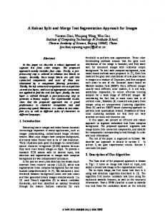
Root mean squared error of training process.
membership functions belong to the generalized bell curve category. RMSE during training process is plotted in Fig 2. Other information about the proposed ANFIS system parameters is as follows: ANFIS info: Number of nodes: 78 Number of linear parameters: 108 Number of nonlinear parameters: 27 Total number of parameters: 135 Number of training data pairs: 432 Number of checking data pairs: 0 Number of fuzzy rules: 27
7. Experimental result Performance of the algorithm was evaluated quantitatively on images from Zhu et al. [9]. The results are evaluated in terms of Per Pixel Accuracy, defined in (16) and Matthews Correlation Coefficient (MCC), defined in (17). Accuracy and MCC is computed in terms of true positives (TP), false positives (FP), true negatives (TN), and false negatives (FN). MCC is a balanced measure which can be used even if the classes are
ð16Þ
ð17Þ
of shadow pixels correctly classified as of nonshadow pixels correctly classified as of shadow pixels incorrectly classified as of non-shadow pixels incorrectly classified
Many works reported in the area of shadow detection from still images have not reported quantitative evaluation of the result [12]. Very few works have reported evaluation in terms of Accuracy [9,11,13]. But, from our experiments, it is observed that Accuracy alone may not provide a better metric in case of shadow detection. Fig. 3 gives an example of a falsely generated result that better explains the failure of shadow detection when evaluated using Accuracy metric. Fig. 3 gives input image, ground truth and result of shadow detection. From the confusion matrix given in Table 1, it is evident that the system has correctly identified the nonshadow pixels (False Negatives = 1) and reported an Accuracy value of 83.16, though the results are not at all satisfactory. However, the MCC (0.3593) value rightly indicates the impairments in performance. Hence, the performance evaluation of the proposed approach is presented in terms of MCC and Accuracy metrics. The Fig. 4(a–d) shows the results of shadow detection using the proposed approach. Input image, ground truth and shadow detected using the proposed approach are given. It is observed that various categories of shadow images such as, shadows cast onto uniform textured surface, non-uniform textured surface and images having self-shadow have provided good result in shadow detection. Confusion matrix of the images used in Fig. 4 is given in Table 2. Per pixel accuracy and MCC of the same images are given in Table 3.
Figure 3 Accuracy of resultant image is 83.16 and MCC is 0.3593. Since False Negative is 1 (see Table 1), the system reports high accuracy value, but MCC is a reasonable indicator of performance.
Please cite this article in press as: Sasi RK, Govindan VK, Fuzzy split and merge for shadow detection, Egyptian Informatics J (2014), http://dx.doi.org/10.1016/ j.eij.2014.11.003
6
R.K. Sasi, V.K. Govindan Table 1 Fig. 3.
Shadow detection confusion matrix of image in
Shadow (GT) Non-shadow (GT)
Table 2 Fig. 3.
Shadow detection confusion matrices of the images in
Shadow
Non-shadow
Fig. no.
Shadow
Non-shadow
0.1563 0.8437
0 1
4(a)
Shadow (GT) Non-shadow(GT)
0.9811 0.0416
0.0189 0.9584
4(b)
Shadow (GT) Non-shadow(GT)
0.8863 0.0311
0.1137 0.9689
4(c)
Shadow (GT) Non-shadow(GT)
1 0.2328
0 0.7672
4(d)
Shadow (GT) Non-shadow(GT)
0.9134 0.0251
0.0866 0.9749
Quantitative evaluation using confusion matrix on Zhu et al. [9] database is given in Table 4. The method has been compared with [16] and found to be better in performance in terms of Accuracy. This can be observed from Table 5.
Figure 4 (a–d) (Top to bottom): Result of shadow detection using images from Zhu et al. [9]. Input image, ground truth, and detected shadow using the proposed approach.
Please cite this article in press as: Sasi RK, Govindan VK, Fuzzy split and merge for shadow detection, Egyptian Informatics J (2014), http://dx.doi.org/10.1016/ j.eij.2014.11.003
Fuzzy split and merge for shadow detection Table 3
7
Per pixel accuracy and MCC of the images in Fig. 3.
Fig. no.
Per pixel accuracy
MCC
4(a) 4(b) 4(c) 4(d)
96.7773 94.33 90.3076 94.8730
0.9397 0.8581 0.7888 0.8900
Table 4 Shadow detection confusion matrix of the proposed approach. Shadow(GT) Non-shadow(GT)
Shadow
Non-shadow
0.9713 0.0755
0.0287 0.8095
Table 5 Quantitative evaluation using per pixel accuracy and MCC of the proposed approach and comparison with [16]. Per pixel accuracy (%) MCC Proposed approach 89.04 Performance of [16] using SVM 85.92 Performance of [16] using Adaboost 83.83
0.7912 – –
8. Conclusion and further work A fuzzy split and merge approach to detect shadow from a single image is proposed in this paper. Fuzzy predicate used in the method is tuned using ANFIS. The approach provides better acceptable performances in terms of Accuracy and Mathew’s correlation coefficient for detecting shadows. The comparative performance study carried out with the existing work demonstrates the superior performance of the proposed approach. References [1] Wu Q, Zhang W, Kumar BV. Strong shadow removal via patchbased shadow edge detection. In: IEEE international conference on robotics and automation; May 2012. p. 2177–82. [2] Lei B, Xu L-Q. Real-time outdoor video surveillance with robust foreground extraction and object tracking via multi-state transition management. Pattern Recogn Lett 2006;27(15):1816–25. [3] Sirmacek, Unsalan C. A probabilistic framework to detect buildings in aerial and satellite images. IEEE Trans Geosci Remote Sens Jan. 2011;49(1):211–21. [4] Yamamoto S, Matsumoto R, Tateno Y, Iinuma T, Matsumoto T. Quoit filter – a new filter based on mathematical morphology to extract the isolated shadow, and its application to automatic detection of lung cancer in X-ray CT. In: Proceedings of the 13th IEEE international conference on pattern recognition; 1996. p. 3–7.
[5] Barrow H, Tenenbaum J. Recovering intrinsic scene characteristics from images. In: Hanson A, Riseman E, editors. Computer vision systems. Academic Press; 1978. [6] Dong Q, Liu Y, Zhao Q, Yang H. Detecting soft shadows in a single outdoor image: from local edge-based models to global constraints. Comput Graph 2014;38:310–9. [7] Weiss Yair. Deriving intrinsic images from image sequences. In: Proceedings of eighth IEEE international conference on computer vision, British Columbia, Canada; 2001. p. 68–75. [8] Jose Jasmin T, Govindan VK. Efficient algorithm for varying area based shadow detection in video sequences. Int J Comput Appl 2013;72(16):20–6. [9] Zhu J, Samuel KG, Masood SZ, Tappen MF. Learning to recognize shadows in monochromatic natural images. In: IEEE conference on computer vision and pattern recognition CVPR, IEEE; 2010. p. 223–30. [10] Miyazaki D, Matsushita Y, Ikeuchi K. Interactive shadow removal from a single image using hierarchical graph cut. In: Proceedings of 9th Asian conference on computer vision, Berlin, Heidelberg; 2010. p. 234–45. [11] Ruiqi Guo, Dai Qieyun, Hoiem Derek. Paired regions for shadow detection and removal. IEEE Trans Pattern Anal Mach Intell 2013;35(12):2956–67. [12] Muthukumar S, Krishnan N, Tulsi Nachiyar K, Pasupathi P, Deepa S. Shadow detection in an image using fuzzy based approach. Int J Inform Comput Technol 2012;2(1):17–26. [13] Lalonde J-F, Efros AA, Narasimhan SG. Detecting ground shadows in outdoor consumer photographs. In: Proceedings of 11th European conference on computer vision, Berlin, Heidelberg; 2010. p. 322–35. [14] Murali Saritha, Govindan VK. Shadow detection and removal from a single image using LAB color space. Cybern Inform Technol 2013;13(1):95–103. [15] Finlayson GD, Hordley SD, Drew MS. Removing shadows from images. In: Proceedings of 7th European conference on computer vision –, London, UK; 2002. p. 823–36. [16] Xiang Huang, Gang Hua, Jack Tumblin, Lance Williams. What characterizes a shadow boundary under the sun and sky? ICCV. IEEE; 2011. p 898–905. [17] Horowitz Steven L, Pavlidis T. Picture segmentation by a directed split and merge procedure. In: Proceedings, 2nd international J. C. on Pattern recognition, Copenhagen; 1974. p. 424–33. [18] Horowitz Steven L, Pavlidis T. picture segmentation by a tree traversal algorithm. J ACM 1976;23(2):368–88. [19] Kelkar D, Gupta S. Improved quadtree method for split merge image segmentation. In: Proceedings, first international conference on emerging trends in engineering and technology, Washington, DC; 2008. p. 44–7. [20] Jang JSR. Anfis: adaptive-network-based fuzzy inference system. IEEE Trans Syst Man Cybern 1993;23(6):65–85. [21] Jang Jyh-Shing Roger, Sun Chuen-Tsai, Mizutani Eiji. Neurofuzzy and soft computing-a computational approach to learning and machine intelligence. IEEE Trans Autom Control 1997;42(10):1482–4.
Please cite this article in press as: Sasi RK, Govindan VK, Fuzzy split and merge for shadow detection, Egyptian Informatics J (2014), http://dx.doi.org/10.1016/ j.eij.2014.11.003