G-lambda and EnLIGHTened: Wrapped In Middleware Co-allocating Compute and Network Resources Across Japan and the US EnLIGHTened:
Steven R. Thorpe5 , Lina Battestilli5 , Gigi Karmous-Edwards5 , Andrei Hutanu6 , Jon MacLaren6 , Joe Mambretti7 , John H. Moore5 , Kamaraju Syam Sundar5 , Yufeng Xin5 G-lambda:
Atsuko Takefusa1 , Michiaki Hayashi2 , Akira Hirano3 , Shuichi Okamoto4,2 , Tomohiro Kudoh1 , Takahiro Miyamoto2 , Yukio Tsukishima3 , Tomohiro Otani4,2 , Hidemoto Nakada1 , Hideaki Tanaka2 , Atsushi Taniguchi4,3 , Yasunori Sameshima4,3 , Masahiko Jinno3 1. National Institute of Advanced Industrial Science and Technology (AIST); Tokyo, Japan {atsuko.takefusa,t.kudoh,hide-nakada}@aist.go.jp
2. KDDI R&D Laboratories; Saitama, Japan {mc-hayashi,okamoto,tk-miyamoto,otani,hide}@kddilabs.jp
3. NTT Network Innovation Laboratories; Kanagawa, Japan {hirano.akira,tsukishima.yukio,taniguchi.atsushi, sameshima.yasunori,jinno.masahiko}@lab.ntt.co.jp
4. National Institute of Information and Communications Technology (NICT); Tokyo, Japan 5. Advanced Initiatives, MCNC; Research Triangle Park, NC, USA {thorpe,lina,gigi,jhm,sundar,yxin}@mcnc.org
6. Center for Computation & Technology, Louisiana State University; Baton Rouge, LA, USA {ahutanu,maclaren}@cct.lsu.edu
7. International Center for Advanced Internet Research (iCAIR), Northwestern University; Chicago, IL, USA
[email protected]
ABSTRACT This paper describes innovative architectures and techniques for reserving and coordinating highly distributed resources, a capability required for many large scale applications. In the fall of 2006, Japan’s G-lambda research team and the United States’ EnLIGHTened Computing research team used these innovations to achieve the world’s first inter-domain coordination of resource managers for in-advance reservation of network bandwidth and compute resources between and among both the US and Japan. The compute and network resource managers had different interfaces and were independently developed. Automated interoperability among the resources in both countries was enabled through various Grid middleware components. In this paper, we describe the middleware components, testbeds, results, and lessons learned.
1.
INTRODUCTION AND MOTIVATION
Scientific discovery and innovation in the 21st century will increasingly rely on what has been called global collaboratories. This term refers to the sharing of resources, interdisciplinary knowledge, and
Permission to make digital or hard copies of all or part of this work for personal or classroom use is granted without fee provided that copies are not made or distributed for profit or commercial advantage and that copies bear this notice and the full citation on the first page. To copy otherwise, or republish, to post on servers or to redistribute to lists, requires prior specific permission and/or a fee. GridNets 2007, October 17-19, 2007, Lyon, France. Copyright 2007 ICST 978-963-9799-07-3
data via information technologies. Several consortiums, forums, and other international communities are addressing some of the many challenges arising from the sharing of resources, such as the Open Grid Forum (OGF)[1] and the Global Lambda Integrated Facility (GLIF)[2]. A key challenge now is to stitch together the resources across the many domains, projects, testbeds, and heterogeneity of the resources. In contrast to conventional Grids which uses the Internet for network connectivity, global collaboratories sometime require the use of high capacity deterministic lightpath connections between resources. In many cases, a single application requires several simultaneous lightpaths in coordination with other resources to run. In this paper we describe the collaboration of two complementary research projects and provide insights to the innovations required for resource sharing and interoperability. Japan’s G-lambda project (GL) [3][4] is a joint collaboration of the KDDI R&D labs, NTT, NICT, and AIST that was started in 2004. The goal of the project is to establish a standard web services interface between a Grid resource manager and a network resource manager provided by network operators. The United States’ EnLIGHTened Computing project (EL)[5] is an NSF seed-funded, interdisciplinary effort among MCNC, LSU, NCSU, RENCI, and several other organizations that began in 2005. It has grown to include several active industry participants (Cisco, Calient Networks, IBM, AT&T Research), national collaborating institutions (StarLight, Caltech, UNCC), and international collaborating projects (Japan’s GL, EU’s PHOSPHORUS). The project has designed an architectural framework that allows e-science applica-
tions to dynamically request in-advance or on-demand any type of Grid resource - not only high-performance computers, storage, scientific instruments but also deterministic, high-bandwidth network paths. Based on application requirements, EL middleware directly communicates with Grid resource managers and, when availability is verified, co-allocates all the necessary resources. In late 2006, these two complementary project teams collaborated to achieve the world’s first inter-domain coordination of resource managers for in-advance reservation of network bandwidth and compute resources between the US and Japan. The compute and network resource managers had different interfaces and were independently developed. Automated interoperability among the resources in both countries was enabled through various Grid middleware components and an innovative architecture. The research described here should be viewed from the perspective of several major investigative areas that are examining new architecture and methods to enhance the efficiency and resource optimization of high performance distributed infrastructure. One consists of attempts to provide for greater levels of abstraction for services supported by infrastructure, such as the trend toward services oriented architecture. Another consists of methods, such as computational grids, for creating distributed resources that can be gathered, configured and reconfigured on an ad hoc basis as required by large scale applications[1]. A third is comprised of new network architectures and techniques that are transforming communication services from static capabilities to highly dynamic directly addressable resources at all network layers, including lightpaths[6]. Projects focused on dynamic lightpath provisioning include OptIPuter, OMNInet, Phosphorus, StarPlane, and DRAGON[7]. Although the research presented in this paper utilizes capabilities from each of these areas, it also provides for a unique middleware architecture for an exceptionally high level of integration among all major distributed infrastructure components within and among distinct domains, including distributed computational grids, high performance communication services, and applications.
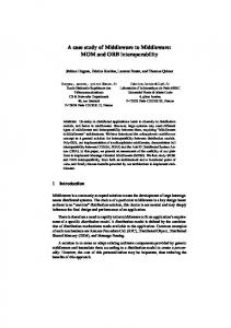
alization application and the GL team has chosen a distributed numerical simulation. Both of these applications have very demanding requirements on both the networks and compute resources as well as strict requirements on the coordination and co-allocation of these resources. Network requirements include the reservation and allocation of multiple lightpaths simultaneously per application, not just a single lightpath. EnLIGHTened Distributed Visualization: Scientific simulations are often carried out on remote computing facilities. Results are stored on one or multiple (in the case of distributed simulations) remote computers. The EL distributed visualization application is targeting the scenario where one scientist needs to interactively visualize and analyze simulation results that are stored on remote supercomputers. One possible option is to copy the entire data to a local resource. However, the dataset size can exceed the local storage capacity and the scientist may only be interested in certain sections of the data, so it would be a waste to transfer the entire dataset locally. Our application instantiates a “data server” code on demand on each of the remote resources holding data of interest, the data servers connect to the visualization client which is instantiated on one of the resources that the scientist has direct access to. Selected data is transferred from the servers to the client and interactively visualized by the user. This is illustrated in Figure 1. G-lambda Distributed Simulation: The GL team’s application was a distributed quantum mechanics/molecular dynamics simulation This surveyed a chemical reaction path by using a nudged elastic band method. The simulation was conducted in parallel, on distributed computing resources, calculating system configurations during the chemical reaction. The remainder of the paper is organized as follows. Section 2 introduces the architectures used by the two teams. Section 3 describes our testbeds. Section 4 covers additional middleware components required to enable interoperability among the two testbeds, along with our coordinated experiments. Finally, in Section 5 we conclude with some of our results, lessons learned, and future plans.
2. SOFTWARE ARCHITECTURES 2.1 Multiple Resource Managers and Brokers With Different Implementations A key goal of our collaboration was to enable interoperability across our respective testbeds and middleware stacks. The GL and EL testbeds consist of multiple domains across Japan and the United states, with each domain managed by its own Network Resource Manager (NRM) middleware. For applications requiring resources in multiple locations, coordinated bandwidth reserved between supercomputers in different domains is required. Three possible models of coordination include 1) Network Control Plane Layer interworking; 2) Local Resource Manager Layer inter-working; and 3) Global Resource Layer inter-working. Details, pros and cons of each of these models are discussed below. Figure 1: EnLIGHTened distributed visualization application
1.1
Applications
Several applications today require this type of dynamic global sharing of resources. Many more are predicted due to the extremely high volume of data being generated in all disciplines. For the interoperability experiment, two representative applications were chosen. The EL team has chosen an experimental distributed visu-
An example of Network Control Plane Layer inter-working would be GMPLS E-NNI. The flow of communication would be from a user program, to a resource coordinator software agent (or broker), to an NRM, to the control plane (e.g. GMPLS). Pros include users not having to care about “multiple domains”. Cons include a) GMPLS is an on-demand protocol and does not support in-advance reservations; and b) a very close relationship between domains is required, which may not always be possible.
Local Resource Manager Layer inter-working refers to a scenario where at path reservation time, an NRM would communicate with “peer NRMs” in adjacent domains to calculate a suitable multidomain path. Then at path instantiation time, each NRM responsible for a portion of the path would issue commands to the underlying control plane in its domain to set up its part of the path. As with the previously described case, pros include users not having to care about “multiple domains”. Cons include a) the complexity introduced by the interworking of NRMs, such as possible political issues to achieve interoperation among NRMs of multiple carriers and b) users can’t control the (intermediate) domains they traverse. In the Global Resource Layer inter-working scenario, a single Resource Coordinator (or Resource Broker) in a user’s local domain communicates with NRMs in multiple domains, and each NRM communicates with its own control plane; there is no communication between NRMs or between the control planes of different domains. Pros include a) the user can control the combination of domains; and b) there is no lower-layer interaction required. It is especially useful for the user to control the domains selected, since it is not just the network provisioning alone that needs to be optimized, but the selected compute and other resources attached to that network also need to be optimized. A Global Resource Layer method allows optimization of network, compute, and other resource choices collectively rather than individually. One con is the broker is required to have knowledge of inter-domain connections. We chose the Global Resource Layer approach for handling our inter-domain connections. In our ongoing research we are studying ways to optimize and share the knowledge of inter-domain connections. At present this issue is largely dealt with using statically configured topological descriptions, but in the longer term we hope to have a more automated resource registry system enabled. The GL and EL teams developed their own resource coordinator and resource manager middlewares independently. Both teams had the goal of achieving in-advance and coordinated reservations of multiple types of resources – especially compute and network. In order to enable interoperability between the projects, we needed to develop software wrappers (described later, in Section 4).
2.2
G-lambda Architecture
work Resource Managers (NRMs), and Compute Resource Managers (CRMs). The GRS reserves overall resources and NRMs and CRMs manage reservation timetables of managed resources and activate the resources at each reservation time. For each user requirement of resources, such as the number of clusters, the number of CPUs, network bandwidth between the clusters, and reservation time, the GRS negotiates with related NRMs and CRMs and books the resources simultaneously based on distributed transactions via a WSRF (Web Service Resource Framework)-based interface[8]. For the interface between the GRS and NRMs, the GL project defines GNS-WSI2 (Grid Network Service - Web Service Interface version 2), a WSRF-based interface for network resources for Grid middleware and applications[9]. GNS-WSI2 provides a two-phase commit protocol to enable a generic and secure advance reservation process based on distributed transactions. GNS-WSI2 provides a polling-based interface and also a notification-based interface using WS-Notification[10]. The GNS-WSI2 reservation process is: 1. A client sends an NRM a creation request of a service instance for resource reservation. The NRM creates a ReservationResource, which is a service instance, and returns an endpoint reference (EPR) to the requested client. The ReservationResource stores reservation property information for each request. 2. Using 1)’s EPR, the client sends a resource reservation request to the NRM. The NRM creates a ReservationCommandResource, to manage information on this reservation request, then returns an EPR to the ReservationCommandResource. 3. Using 2)’s EPR, the client checks the reservation status of at the NRM. After the NRM has prepared the requested resources, the NRM returns status “Prepared”. This completes phase 1 of the two-phase commit protocol. 4. In order to confirm the reservation, the client sends a commit request using 2)’s EPR, completing phase 2. User/GRS and GRS/CRM interfaces also use a WSRF-based twophase commit protocol similar to that of GNS-WSI2. This hierarchical two-phase commit protocol enables the GRS to itself be a resource manager, so it can easily coordinate with other global schedulers or co-allocators. For description of compute resources, we extended JSDL (Job Submission Description Language)[11] to represent requirements of advance reservations. In the experiment with the EL team, we used GridARS (Grid Advance Reservation-based System framework) GRS[12] and multiple NRM implementations developed by KDDI R&D Labs., NTT, and AIST, respectively. For CRMs, we used a GridARS WSRF interface module and existing compute resource schedulers, PluS[13] and GridEngine[14]. PluS is a plug-in scheduler enabling advance reservation capability for existing queuing systems.
Figure 2: G-lambda middleware architecture The architecture of the GL middleware is shown in Figure 2. The middleware consists of a Grid Resource Scheduler (GRS), Net-
To perform the GL distributed simulation application, an application portal was developed. The portal architecture is shown in Figure 3. The portal frontend was developed using Java Script and a Java Applet; it calls GRS reservation operations via an HTTP interface. For each user request from the frontend, GL middleware books suitable network and compute resources. After the reservation has completed, the user launches an application result viewer from the portal frontend and the portal submits user jobs in the reserved queues via WS-GRAM, as provided by Globus Toolkit 4.
distributed operation for multi-layer provisioning and synchronization of the network state.
Figure 3: G-lambda’s application portal architecture When a parallel application is executed using multiple clusters, we may need provisioned paths between some cluster pairs, but we may not need paths between certain pairs of clusters since the traffic is low between these pairs. In such cases, user process should communicate both using the provisioned data plane paths (where available) and ordinary (but always available) routed network. To realize this, we set and reset routing tables of computing nodes before and after a provisioning. Before executing a scheduled job, PluS activates a pre-job, in which the routing table of each node is set appropriately for the execution of the job. After job execution, the routing tables are reset to the original state by a post-job. Using this function, user processes can communicate with nodes in other sites through data plane and cluster management plane using a single IP address. The GL team’s north and south domains (described in Section 3) are managed by NRMs developed by KDDI R&D labs. and NTT respectively. These two NRMs have different implementation, while both support the same GNS-WSI2 interface.
2.2.1
NRM developed by KDDI R&D Laboratories
A concept of network resource management system (NRM) has been proposed to provide the network service via WSI, and that was demonstrated using JGN II GMPLS testbed for the first time [15]. Moreover, to support latency-aware advance reservation with optimized network resource utilization, adaptive path discovery and allocation schemes with optimized bandwidth resource scheduling mechanism were introduced[16]. The NRM developed by KDDI R&D Laboratories Inc. mainly consist of three functional modules: WSRF-based Web services module, mediation module, and network control and management (C&M) module) [16], as shown in Figure 4. A Web services module cooperates with the GRS through the GNS-WSI2 web-services API. The NRM provides guaranteed and scheduled network service to network service clients. A Web service module of NRM handles service messaging using Web application server (Web AS). Following a request processed by Web service module, a mediation module assigns appropriate resources using optimized-path discovery and scheduling functions. A mediation module allows both on-demand and in-advance network services. The information of reservation and network resource are dynamically managed by a transaction and a resource databases, respectively. A network control and management (C&M) module interworks with the control plane (e.g. MPLS, GMPLS) of physical network and utilizes its
Figure 4: Architecture of NRM developed by KDDI
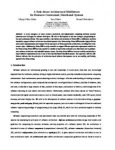
Figure 5: Path discovery operation up to 3rd stage from nodeA in IP/optical network. The shortest path first (SPF) algorithm is used in IP and optical networks to find the shortest path based on a current topology, and the constraint-based SPF widely implemented to GMPLS networks allows handling of TE-link attributes. However, these techniques are not essentially designed to handle resource availability with the time domain and latency as constraints. We have proposed a path discovery scheme based on the breadth first search to obtain possible paths[16]. Using a currently available topology stored in the resource database of NRM, possible end-to-end routes are discovered in advance considering the link attributes. Figure 5 shows the breadth first search-based discovery operation up to the 3rd stage in the case of a 2.4 Gbit/s path from a packet switch capable (PSC)node A through lambda switch capable (LSC) transit nodes. The stage progresses on a per hop-basis and possible links with the same attributes are selected to produce an end-to-end route that is managed as a logical tunnel (LSP). Then, each LSP has an end-to-end latency value that is integrated from component links. In the 3rd stage shown in Figure 5, discoveries from nodes C and I detect the loop for a route to node B. Based on this scheme, the NRM allocates appropriate LSPs based on conditions injected from clients.
2.2.2
NRM developed by NTT
In the GL/EL collaboration, a network resource manager[17] developed by NTT is responsible for management of the JGN II south domain’s network, over which GMPLS control plane has been superposed[18]. This NRM consists of Web Service (WS)-adapter, scheduler, path data base, and path control manager modules as shown in Figure 6. The scheduler module is invoked by a reservation request received from the AIST-GRS via WS-adapter which is compliant to GNS-WSI2. The scheduler module computes an available route according to the reservation request. If it finds a
route, it registers the route in the database and returns the result to the GRS via the WS-adapter. Several seconds prior to the reserved time, the path control manager initiates GMPLS RSVP-TE signaling to provide the requested connections in time for the application. Then when the ending time comes, it invokes tear down signaling.
resources. To co-allocate a resource set, clients send their request (expressed as a single XML message) to the Acceptors. For HARC to be able to book the multiple requested resources in an atomic fashion, a phased-commit protocol is used. HARC uses the Paxos Commit protocol [20], which allows the system to function normally, provided a a majority of the Acceptors remain operational. The current implementation of HARC includes:
Figure 6: NTT-NRM architecture
2.3
EnLIGHTened Computing Architecture Figure 8: HARC Network Resource Manager
Figure 7: EnLIGHTened middleware architecture The architecture of the EL middleware is shown in Figure 7. The middleware doesn’t yet include automated resource selection, often referred to as resource brokering. In the current implementation, this is manually performed by users, who specify the exact compute and network resources they wish to use, and at which times. To initiate its activities, the application uses a set of scripts we call the Application Launcher/Steerer (ALS). The ALS requests resources for the application from the Highly-Available Resource Co-allocator (HARC) Acceptors. The HARC Acceptors attempt to co-allocate the required resources for the selected time range by using the HARC Network Resource Manager (NRM) and the Compute Resource Managers (CRMs). HARC is an extensible, open-source co-allocation system that allows clients to book multiple heterogeneous resources in a single transaction [19]. It consists of a set of Acceptors, which manage the co-allocation process, and a set of Resource Managers, that provide the interfaces for HARC to make reservations on individual
• Network Resource Manager (NRM): for reserving dedicated lightpaths on a single-domain optical network such as the EL testbed. The HARC NRM’s components are illustrated in Figure 8. Within the HARC NRM, a model of each link within its domain’s topology is maintained, along with a timetable for each link that contains a set of time ranges that link has been reserved for. The domain’s topology and link characteristics are loaded when the NRM starts, and this HARC NRM is assumed to have complete control over its domain’s paths. For paths connecting any two end points in the topology, the HARC NRM has TL1 commands specifying an Explicit Route Object (ERO) to connect those end points. These paths and corresponding links and timetables are searched at user request time, in order to choose an appropriate answer to service the request. At connection reservation time, TL1 commands are sent to Calient Diamondwave PXCs to initiate lightpaths by GMPLS RSVP-TE. Ideally timetables would not actually be maintained within the HARC RM, but rather any HARC RM would be a much thinner layer between the Acceptors and a true resource manager underneath (as is the case with the CRM, described below). However, as the network has no such resource manager, keeping these in this prototype HARC NRM was simpler. • Compute Resource Managers (CRMs): for reserving time on High-Performance Computing resources, via existing batch schedulers such as PBSPro, Torque with Maui, etc. In essence, the CRMs wrap an existing scheduler so that it can work with other middleware components. The reservation ID is passed back to the requestor, and is used when submitting the job to the scheduler via the Globus GRAM protocol.
3.
NETWORKS AND GRID TESTBEDS
The foundation for success of the middleware development is to equip the underlying physical network elements with necessary dynamic provisioning capabilities. There are two interesting areas that most of the research and development efforts have been put on: (1) To better understand the control and management capabili-
also uses this plane. The control plane is for GMPLS messages.
Figure 9: Map of network and compute resources ties that the network system can provide in the near future. Therefore the middleware development can be done in a most efficient way by making the best use of these capabilities. (2) In parallel, to understand and experiment the most updated control and management capabilities in the network system. The objective is to find the optimal meeting point for middleware development and Grid network and compute system development. To emulate a wide area environment with a meaningful scale, the EL project has developed a testbed with a national footprint. On the GL side, the testbed consists of compute resources distributed in multiple sites connected by the JGN II research and education network. Figure 9 illustrates the combined resources. The most advanced network control feature deployed in both testbeds is GMPLS and PXC (Photonic Cross Connect) technologies, which gives capability to provision on-demand high-speed circuits in multiple granularities, up to 10 Gbps. While some arguments are still ongoing regarding the appropriateness of deploying GMPLS in a wide-area Grid system with multiple domains, we have concluded that GMPLS can give multiple options for the middleware and applications to call upon in a generic manner. These include topology discovery, traffic engineering, path computation, path reservation, and signaling capabilities provided by the LMP, OSPF-TE, RSVPTE, and ENNI protocols within the GMPLS protocol suite. Two different methods of inter-domain circuit provisioning were demonstrated. The first was achieved with middleware, as described in the rest of this paper. The other was via manual inter-domain provisioning using ENNI between domains, as described in [21].
3.1
G-lambda Testbed
Network Resources: The GL testbed uses the JGN II research network, including the Tokyo-Chicago international line. JGN II is an open testbed network established by NICT in April 2004 for the purpose of promoting R&D activities of advanced networking technologies and network-related applications [22]. It includes two GMPLS administrative domains: Japan North and Japan South. Each domain consists of multiple OXCs and GMPLS routers. In the GL testbed, there are three network planes: the data plane, the cluster management plane and the control plane. Data plane paths are provisioned according to reservation requests from users. The data plane is a Layer 3 network. Communication among middleware uses the cluster management plane, a best-effort always available network. Non bandwidth demanding user communication
We have demonstrated control plane interoperability by advanced GMPLS ENNI [21] [23]. However, in this experiment, GMPLS was not used for inter-domain connections. An inter-domain path is realized by a back-to-back static route connection of GMPLS routers at the edge of intra-domain paths. Two virtual domains, X1 and X2, were used to support inter-domain path provisioning. These are modeled as exchange points at which paths in two domains are interconnected – an OXC or equipment with some switching capability is assumed. However, due to a lack of such functionality in our network equipment, the virtual domains are implemented using ordinary L3 routers. The NRM which manages these domains, developed by AIST, does not actually manage equipment. However, the NRM regulates the reserved bandwidth between domains by summing up the requested bandwidth of reservations. If the sum exceeds a pre-determined threshold, a reservation is not granted. Compute Resources: Seven sites each with a computing cluster are connected by the testbed network: the sites TKB, KMF, KAN and FUK in the north domain; and AKB, OSA and KHN in the south domain, as shown in Figure 9. Each of these clusters (which are dedicated to this experiment) consists of between 3 and 32 computing nodes (either IA32 or Opteron based), and is connected to the data plane through a router by a Gigabit Ethernet link.
3.2
EnLIGHTened Testbed
Network Resources: The EL testbed is a national-footprint optical (Layer 1) network deployed to facilitate middleware and application goals, as well as to support investigations into new network and control plane architectures. The core of the testbed is built using Calient Networks Diamond Wave photonic cross-connect switches interconnected by 10-GbE circuits provided by Cisco Systems and National Lambda Rail. GMPLS is used as the control plane protocol to allow dynamic instantiation of end-to-end paths across the testbed. Each site that hosts a PXC also provides 10-GbE-attached switches and/or end hosts as well as the potential to extend connectivity to users and resources via local Regional Optical Networks. In the experiment, the EL testbed becomes a GMPLS domain that is connected to the two JGN II domains via the virtual domain X1. Compute Resources: The EL testbed interconnects five geographically-distributed compute cluster facilities: (1) Los Angeles, CA (Caltech), (2) Baton Rouge, LA (CCT at LSU), (3) RTP, NC (MCNC), (4) Raleigh, NC (VCL at NCSU) and (5) Chicago, IL (StarLight). These dedicated clusters consist of high-end PCs with 10 GE network interface cards or a cluster of up to 64 CPUs.
4.
EXPERIMENT INTEROPERABILITY
A major goal of our collaboration that started in 2006 was to achieve an inter-domain coordinated in-advance reservation of both network bandwidth and compute resources between multiple domains on both continents. Another goal was to continue using our independently developed middleware stacks on our respective testbeds. In order to reach these goals, a set of wrappers were written to bridge the differences between the two teams’ APIs. The wrappers are shown within Figure 10, and described in this section.
4.1
Wrappers Around EnLIGHTened
The EL->GL GNS-WSI Wrapper translates requests from the GL GRS to the EL HARC middleware. The GRS invokes the wrapper
Figure 10: EnLIGHTened / G-lambda interoperability using GNS-WSI2 (as it would to a native GL NRM); the wrapper then makes requests to the HARC acceptors to realize the management of network resources – setup, teardown, canceling, etc. The EL->GL CRM Wrapper was implemented by the GL team, to make advanced reservations of EL compute resources available to the GL GRS. This component talks the GL team’s CRM protocol with the GRS, but acts as a client to the HARC Acceptors, translating between formats accordingly. Both of these wrappers are implemented as WSRF services, running within GT4 containers.
4.2
Wrapper Around G-lambda
Figure 11: Map of network and compute resources as displayed by G-lambda’s Reservation Resource Monitor viewer • [NRM/CRM] Start time, End time, endpoints from NRM, reserved bandwidth/number of CPUs, and reservation statuses The EL Grid Resource Coordinator (GRC), a Tomcat-hosted webservice, enabled the GL RRM Viewer to visually display resources reserved by the EL middleware in a color-coordinated fashion, alongside the GL initiated requests. When any reservation was made (or canceled) by the HARC acceptors, an XML message was pushed to the GRC. The GRC parses this XML to extract the IDs needed to service getReservationIDMap() requests from the RRM.
The GL->EL Wrapper is a perl-based component that provides a single HARC Resource Manager interface to the G-lambda team’s network and compute resources. Requests for combined G-lambda network and compute resources are sent from the HARC Acceptors to the GL->EL Wrapper. The wrapper reformats then communicates these to the GL GRS for realization. This method of wrapping is not as elegant, as the EL Application Launcher must package requests for the GL resources in a different way from the EL resources. However, the alternative—i.e. the construction of two wrappers around each of the GL CRM and NRM components— was not possible given the time-frame.
In addition to the information from the middleware, in the EL testbed we monitored the ongoing reservations by talking directly to the network elements and clusters. For this, we used Caltech’s MonALISA [24]. We monitored our clusters, Ethernet switches and Optical switches. Using MonALISA we also created a centralized repository for a unified view of the resource status and statistics. Using MonALISA’s Optical Module we communicated to the optical switches and retrieved port optical power level and crossconnect information. We used MonALISA’s GUI to watch in realtime the setting up and tearing down of the lightpaths and the load on the Ethernet switches and the clusters.
4.3
5.
Experiment Monitoring
Although the wrapper modules enable reservation of inter-domain resources, they do not address the complexity of monitoring all the resources across the two testbeds. To resolve this problem, the GL Reservation Resource Monitor (RRM) system was used to collect reservation information from both coordinators (GL GRS and EL GRC), NRMs, and CRMs. The RRM consists of a Viewer and Aggregator. In the GL and EL middleware stacks, NRMs and CRMs manage the status of reserved resources, such as Reserved, Activated, Released, or Error, and coordinators manage mapping information of each user reservation requirement and resource reservation. The Aggregator periodically collects the following information (formatted in XML) from the GL GRS, EL GRC, NRMs, and CRMs; the Viewer then displays a dynamic representation of all the ongoing reservations as shown in Figure 11: • [GRS/GRC] Coordinator name (EL / GL), resource reservation (request) ID, CRM and NRM names of the coordinator-domain resources, and the other coordinator name (GL / EL) for the other domain resources for each user request.
CONCLUSIONS AND FUTURE WORK
We were delighted to achieve our collaboration’s initial goal of inter-domain coordinated in-advance reservation of both network bandwidth and compute resources among multiple domains on two continents, and in time for demonstrations at the GLIF 2006 and Supercomputing 2006 meetings. This effort has reinforced our understanding that writing software wrappers to translate among different interfaces is a difficult, timeconsuming, and error prone task. In fact this effort could easily increase exponentially as additional peer projects get added to the mix. We emphasize the importance of agreeing upon API standard definitions that can be commonly adopted by all such collaborating projects. Regardless of the underlying implementation of e.g. Network Resource Manager, Compute Resource Manager, and Resource Broker functionality, it is imperative to work towards common APIs these stacks can all avail themselves of. In this way we can cooperate much easier on the widely distributed collaborative eScience projects of the future. Therefore we intend to work with the high performance networking and computing communities to
[5] EnLIGHTened Computing Project Website. http://www.enlightenedcomputing.org. Here we focused on achieving interoperability to allocate compute [6] G. Karmous-Edwards et al. Grid networks and layer 1 and network resources. However we need to mention that achievservices. Grid Networks: Enabling Grids with Advanced ing interoperability to the level where applications can take adCommunication Technology (F. Travostino and J. Mambretti vantage of the infrastructure requires much more than that. One and G. Karmous-Edwards (Ed.)), Sep. 2006. important issue is the interoperability of the respective compute [7] J. Mambretti and T. Aoyama. Report of the Interagency “grids”. Independent of the network connectivity of the resources Optical Networking Workshop 3, Networking and in the two domains, the grid middleware needs to be configured Information Technology R & E Program’s Large Scale such that seamless integration of the two or more virtual organizaNetworking Group, May 2007. tions is possible. This is still an area of research in Grid computing [8] Web Services Resource 1.2 (WS-Resource) OASIS Standard, and something we need to address in the future in order to have a April 2006. clean integration of the two testbeds. Another important issue is [9] A. Takefusa et al. GNS-WSI2 Grid Network Service - Web to consider application-specific requirements. For example the disServices Interface, version 2. OGF19, GHPN-RG, 2007. tributed simulation run by the GL team requires a specific type of [10] Web Services Base Notification 1.3 (WS-BaseNotification) a grid-enabled MPI platform which requires the grid middleware Public Review Draft 02, November 2005. interoperability described above. While running the distributed vi[11] A. Anjomshoaa et al. Job Submission Description Language sualization experiment we realized that the performance of the TCP (JSDL) Specification v1.0, 11 2005. transport protocol across wide-area networks using the default TCP [12] A. Takefusa et al. GridARS: An Advance Reservation-based parameters is disastrous (under 10 Mbps for a 200 ms RTT, 1 Gbps Grid Co-allocation Framework for Distributed Computing link from Japan to US). The solution was not different transport and Network Resources. In Proceedings of the 13th protocols, but rather configuring the TCP parameters on the endWorkshop on Job Scheduling Strategies for Parallel hosts for particular application scenarios is required. Because the Processing (To appear), 2007. configuration of these parameters depends on the resources used by [13] H. Nakada et al. Design and Implementation of a Local the application, this probably needs to be done on-demand. Scheduling System with Advance Reservation for Co-allocation on the Grid. In Proceedings of CIT2006, 2006. Future work also includes software design changes within our re[14] Grid Engine. http://gridengine.sunsource.net. spective stacks. We will introduce security functions where possi[15] M. Hayashi et al. Managing and controlling GMPLS ble. We plan to refactor the timetable and network management canetwork resources for Grid network service. In OWQ3, pabilities of the HARC NRM into a separate NRM implementation, OFC2006, 2006. with a thin HARC RM interface to that NRM. An ongoing discussion and investigation is considering whether to move towards plain [16] M. Hayashi et al. Advance reservation-based network Web Services or RESTful XML over HTTP(s) SOA models, rather resource manager with adaptive path discovery scheme for than the more heavyweight WSRF-based method currently being SOA-based networking. In OWK2, OFC2007, 2007. used. Finally, we have involved third partner in 2007: the EU’s [17] Y. Tsukishima et al. The first optically-virtual-concatenated PHOSPHORUS project[25]. Our goal is a common interface that lambdas over multiple domains in Chicago metro area enables interoperability among multiple organizations’ resources. network achieved through interworking of network resource managers. In Tech. Digest of OECC/IOOC2007 (in press), 2007. Acknowledgments [18] W. Imajuku et al. GMPLS Based Survivable Photonic EL is partially funded by NSF award #0509465. AIST is partially Network Architecture. In IEICE Trans. Commun. (in press), funded by the Science and Technology Promotion Program’s ”OpAugust 2007. tical Paths Network Provisioning based on Grid Technologies” of [19] HARC: Highly-Available Resource Co-allocator. MEXT, Japan, which AIST and NTT are jointly promoting. Thanks http://www.cct.lsu.edu/∼maclaren/HARC. also to: C. Hunt, A. Mabe, M. Johnson, G. Allen, L. Leger, E. Sei[20] J. Gray and L. Lamport. Consensus on transaction commit. del, R. Paruchuri, M. Liˇska, P. Holub, A. Verlo, X. Su, Y. Xia, Technical Report MSR-TR-2003-96, Microsoft Research, M. Vouk, H. Perros, S. Tanwir, B. Hurst, L. Ramakrishnan, D. Reed, January 2004. A. Blatecky, F. Darema, K. Thompson, D. Fisher, T. West, J. Boroumand, [21] S. Okamoto et al. First demonstration of end-to-end W. Clark, R. Gyurek, K. McGrattan, P. Tompsu, S. Hunter, J. Bowinter-domain lightpath provisioning using gmpls e-nni ers, O. Jerphagnon, M. Hiltunen, R. Schlichting, Y. Tanaka, F. Okazaki, between us and japan for high-end data and grid services. In S. Sekiguchi, H. Takemiya, M. Matsuda, S. Yanagita, K. Ohkubo, IEEE OFC’07, Mar. 2007. M. Suzuki, M. Tsurusawa, R. Suitte, T. Leighton, S. Rockriver, [22] JGN II. http: T. Koga, Y. Okano, Y. Takigawa, W. Imajuku and T. Ohara. //www.jgn.nict.go.jp/english/index.html. [23] Y. Sameshima et al. JGN II Testbed Demonstration of 6. REFERENCES GMPLS Inter-Carrier Network Control with Actual [1] Open Grid Forum. http://www.ogf.org. Operational Consideration. In We4.1.5, ECOC2006, 2006. [2] Global Lambda Integrated Facility (GLIF). [24] MonALISA Web Page. http://www.glif.is. http://monalisa.cacr.caltech.edu, February [3] G-lambda Project Website. 2006. MONitoring Agents using a Large Integrated Services http://www.g-lambda.net/. Architecture. [4] A. Takefusa et al. G-lambda: Coordination of a Grid [25] PHOSPHORUS Project Website. Scheduler and Lambda Path Service over GMPLS. Future http://www.ist-phosphorus.eu. Generation Computing Systems, 22(2006):868–875, 2006. achieve definitions for APIs such as these.