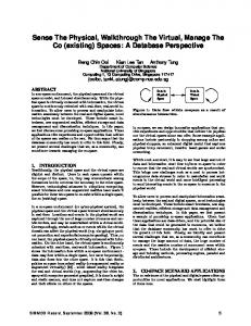
Jun 22, 2005 - Figure 1: Four small patches are extracted from an input texture to form 16 different texturing blocks; .... the four sides of I. The curve is also restricted to lie inside a ..... tuples with âdon't careâ conditions for their fourth elements.
Generating an ω -Tile Set for Texture Synthesis Tuen-Young Ng†, Conghua Wen, Tiow-Seng Tan†
Xinyu Zhang‡, Young J. Kim‡
School of Computing National University of Singapore, Singapore
Dept of Computer Science and Engineering Ewha Womans University, Korea
Figure 1: Four small patches are extracted from an input texture to form 16 different texturing blocks; an example of such a block is shown on the left. A tile is cut from the center of each block to obtain in total 16 ω-tiles as shown on the right. The color at each corner of an ω-tile indicates the color of the patch that contributes to the corner. The interior (shown within each curve) of each ω-tile is obtained by sampling another patch from the input texture.
Abstract This paper presents an effective approach to generate a set of small textures from an input texture that can be tiled together to synthesize large textures. Such a small set can be useful in texturing any large area realistically and efficiently while consuming only a small amount of texture memory. Our approach is advantageous in its ability to generate a smaller number of tiles that can embed much more texture patterns and with less conspicuous seams within each tile than earlier approaches. As a result, our approach can generate large textures that look as if each were from a continuous part of the input texture while avoiding highly repetitive patterns. In general, our approach performs very well and shows a particular strength, compared to earlier approaches, for input textures of elaborate or relatively large features, or with distinctive colors. CR Categories: I.3.3 [Computer Graphics]: Picture/Image Generation; I.3.6: [Computer Graphics]: Methodology and Techniques; I.4.3 [Image Processing]: Smoothing Keywords: non-repetitive tiling, Wang tile, image generation 1. INTRODUCTION From a given input texture, texture synthesis is to generate large textures, i.e. synthesized textures that maintain the underlying global distribution pattern of the input texture. In some applications, a large synthesized texture is pre-computed from a small input texture to texture map a large area; see, for example, the pixel- [4, 6, 9, 21] and patch-based [1, 5, 13, 15] synthesis approaches. In other, a set of small textures is pre-computed from an input texture for use to tile into a large texture (during real-time rendering). This avoids the need for a large texture memory when texturing a large area. The main focus of this paper lies in the latter usage of texture synthesis. †
e-mails: {ngtuenyo, tants}@comp.nus.edu.sg e-mails: {zhangxy, kimy}@ewha.ac.kr
‡
The 2005 Computer Graphics International, 22-24 June, Stony Brook, New York, USA.
Our work is motivated by the approach provided in [3] that generates a set of square texture tiles, called Wang tiles, for tiling to form large textures. We propose a novel and competitive approach to create a new set of texture tiles, called ω-tiles. The approach first extracts four small patches from an input texture S to arrange them into blocks to derive ω-tiles; see Figure 1. Our approach addresses the following three important issues arising in generating a set of tiles for texture synthesis: • • •
The content of each tile should look as if it were a continuous part of S. Tiles should be seamless across the boundaries in their synthesized textures. A large synthesized texture from these tiles should maintain the underlying global distribution pattern of S.
Our approach, first of all, addresses the possible seams occurring inside a tile by providing a large search space so as to control the seams that can result from combining patches in S. Furthermore, seams within each tile form a closed curve (rather than a cross as in previous approaches), and they can be softened using a Poisson approach [16]. Secondly, the seams between two ω-tiles adjacent to each other are avoided by matching the sides of two patches from S. Note that the junctions where four patches from S meet must be treated with care, as they are particularly conspicuous to human eyes [8, 19]. Our approach allows a high degree of control of the content at junctions as two of the four textures at each junction are obtained by a careful searching. Finally, our approach achieves a good underlying global distribution pattern of S in the synthesized texture as it can embed diverse texture patterns in ω-tiles. The patterns in ω-tiles are not restricted to the four patches initially extracted from S. The rest of the paper is organized as follows. Section 2 highlights previous work on texture synthesis, in particular the approach of Wang tile [3]. Section 3 describes the creation of ωtile in our approach. Section 4 presents our approach to generate a set of ω-tiles and synthesize large textures with less repetitive patterns. Section 5 presents our experimental results, and Section 6 concludes the paper with limitations of our approach and suggestions on future work.
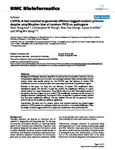
2. PREVIOUS WORK There are a few methods to synthesize a large texture. First of all, the procedural texturing [7, 17, 22] can generate details at arbitrary resolutions with no periodicity and very low memory. However, there are certain material aspects of textures that cannot be generated using these techniques. Secondly, pattern-based texturing uses a set of different, small texture patches to define a pattern. These small patches are used to tile a large area while avoiding the periodicity and repetitiveness of a naïve tiling. Examples of this method include aperiodic tiling [20], triangular patterns [14], virtual atlases [18], sparse convolution [12], chaos mosaic [23] and Wang tile [3]. These approaches generally need more texture memory than the procedural texturing, but require a lower computational cost during rendering. Lastly, the pattern-based procedural texturing [11] combines the aforementioned two methods. It determines the texture value at any surface location by combining the provided patterns in an aperiodic manner according to user-defined controls such as a probability distribution and animation of textures. This method provides a sophisticated control to texture a large area with the texture indirection ability available in recent graphics processing units. In general, the method requires more computations during rendering than the pattern-based texturing. Our work is related to that of Cohen et al. [3] on Wang tiles. A set of Wang tiles is created where each tile is obtained from a different arrangement of four (or more), not necessarily distinct, patches overlapping in small regions, as shown in Figure 2(a). The overlapping regions are used to compute cutting paths to define the four partitions contributed by each patch. Cutting paths can result in prominent seams between patches and are thus computed with different criteria such as minimizing the difference in pixel values across the patches. We note that the generation of Wang tiles as implemented by Burke [2] adapts an alternative overlapping arrangement to combine four sample patches; see Figure 2(b). The sample patches used are of the same size as the output Wang tiles. In general, this alternative is easier to implement and provides a larger overlapping area to search for better cutting paths. 3. CONSTRUCTION OF A TILE Our approach starts with randomly obtaining a set F of four small square patches from the input texture S. With these, it forms each time a square block to construct eventually an ω-tile. Each block is a non-overlapping arrangement of four (not necessarily distinct) patches of F. Figure 3 shows an example of four such blocks A, B, C and D (obtained from different arrangements of the four patches in F) and the intermediate tiles Ai, Bi, Ci, and Di cut from the center of A, B, C and D. The seams in each intermediate
(a)
(b)
Figure 2: (a) Four square patches (shown in different colors) are combined to form a diamond block to extract a Wang tile at the center. (b) An alternative overlapping arrangement used by Burke [2] to combine four square patches to extract a Wang tile (of the same size as the square patches).
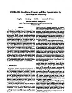
tile are removed by replacing the interior of the tile with other pattern from S to generate an ω-tile. Sections 3.1 and 3.2 discuss the removal of the vertical and horizontal seams in an intermediate tile with cutting curve, and Section 3.3 the softening of seams around the cutting curve with Poisson smoothing [16]. 3.1 Cutting Path and Cutting Curve We note that the middle of each Wang tile is a junction where four patches meet; see Figure 2. Such a kind of a junction, due to cutting paths, also occurs at the corners of each Wang tile in tiling a large area. These are the seams that can be prominent to the naked eyes; the contents around them should be controlled if possible. For junctions at the corners of four Wang tiles, there is no known, good way to control the cutting paths to minimize the prominence of junctions. Cohen et al. call this the corner problem, and suggest, for example, expanding from a set of 8 Wang tiles to at least 64 Wang tiles with matching corners. This, however, demands more texture memory during rendering. One of our aims is to reduce the prominence of junctions. Our approach searches a good pattern C to replace the interior portion inclusive of the vertical and horizontal seams in each intermediate tile. Such a pattern is enclosed by a closed curve, termed a cutting curve, passing through the middle point of each side of the intermediate tile. As a result, when these tiles are laid on a large area with matching sides, the junctions where four textures meet appear in the middle point of each side; see the center picture of Figure 3. In Wang tiles, junctions are resulted from a fixed set of patches that generates the Wang tiles, whereas in ω-tiles, two out of four patches meeting at a junction are obtained by searching good patterns in S. Thus, our approach has good control of the content at each junction and thus good chances to avoid the prominence of junctions.
Figure 3: Four intermediate tiles Ai , Bi , Ci and Di cut from blocks A, B, C and D, respectively, are used to generate four ω-tiles Aω , Bω , Cω and Dω , which, in turn, tile the 2-by-2 area in the middle.
3.2 Computation of Cutting Curve From S, we can pick a patch O (Figure 4(b)) of the same size as the intermediate tile I (Figure 4(a)) to be a candidate with a part of its interior to replace the corresponding part of the interior of I. Each candidate O is first superimposed on I to compute a cutting curve (Figure 4(c)), passing through the middle points of the four sides of I. The curve is also restricted to lie inside a (pink) circle with the same center as I and having the diameter equal to the width of I. The area of I within the cutting curve is then replaced by the corresponding content C in O (Figure 4(d)). The best C, from all possible candidates O available from S, is one where the seams along the cutting curve are least prominent. Figure 5: A schematic diagram of the graph problem to compute a cutting curve within the circle.
(a)
(b)
(c)
(d)
Figure 4: (a) Intermediate tile I with vertical and horizontal seams across patches. (b) A candidate O extracted from S. (c) The intermediate tile of (a) with its interior removed along a cutting curve. (d) The removed part is replaced by the corresponding part C of O to obtain an ω-tile as shown.
To derive a C, we adopt the method of Kwatra et al. [10]. In essence, their work formulates the problem of calculating a cutting path for a given pair of patches I and O as a graph problem. The method regards pixels in the overlapping area as nodes and the link between any two neighboring pixels as an edge in the graph. Moreover, each edge is assigned a weight as a flow capacity which is the sum of the transition errors of the two nodes divided by the sum of their gradients in the patches:
Weight ( s, t ) =
I ( s ) − O( s ) + I (t ) − O(t ) GI ( s ) + GI (t ) + GO ( s ) + GO (t )
where s, t are neighboring pixels (sharing a side) in the overlapping area; I(s) and I(t) are the values of pixels s and t, respectively, in patch I; O(s) and O(t) are the values of pixels s and t, respectively, in patch O; GI ( s ) denotes the gradient of pixel s in the patch I along the gradient direction from s to t, and GI (t ), GO ( s ), GO (t ) are similarly defined. Then, the cutting path is calculated as a min-cut which cuts the graph edges with a minimum sum of flow capacities from the source pixels of I to the sink pixels of O. We adapt the above technique to find a cutting curve shown as in Figure 5. We have (shaded) pixels of I outside the circle defined as sources, two vertical columns and two horizontal rows of (shaded) pixels at the center of O defined as sinks, and weights
of edges incident to white pixels defined as in the above Weight function. In practice, one can employ heuristics to avoid computing the above cutting curve for all possible choices of O to locate the best C. We can choose to examine just a single or a few O’s to compute a good enough C. One possible heuristic is to pick O with the smallest sum of weights for the pixels around the (pink) circle (in Figures 4(a) and 4(b)). This is an attempt to select O that is similar to I and thus with a good chance of obtaining a cutting curve with less prominent seams. We use this heuristic in our experiments reported in Section 5. An alternative choice is to pick O with the smallest sum of weights for the pixels near the middle of the four sides. This is to emphasize the importance of having matching contents at junctions. With the above process, each ω-tile obtained has generally less than a half of its area occupied by patches in F and the remaining occupied by some other patch in S. The interesting result is that for a set of 16 ω-tiles, for example, used in synthesizing a large texture, there are twenty different patches (randomly chosen) from S appearing in the large texture, and less than half of the area is occupied by the patches in F. Due to the many sample patches, all or large aspects of the source texture S generally do appear in the synthesized texture. This is observed in our experiments as long as each of the twenty sample patches has size at least twice the sizes of prominent patterns/objects in S. In comparison, large texture synthesized by Wang tiles is fully filled by, for example, the four patches initially generating the set of Wang tiles. Thus, a set of ω-tiles is a more attractive option than a set of Wang tiles in avoiding repetitive patterns in synthesizing large textures, and can better preserve the underlying global distribution pattern of S. 3.3 Poisson Smoothing For some input textures, it remains challenging to obtain good cutting curves (as well as cutting paths) to avoid prominent seams in resulting ω-tiles. We observe one such class of input textures as having elaborate or large features or with distinctive colors. For these input textures (such as the two shown in Figure 10), we have found that the Poisson approach to guided interpolation in [16] is effective in removing prominent seams in ω-tiles. Using the approach and the terminology defined in [16], we let C (as defined in Section 3.1) be the source image, and I (as defined in Section 3.2) be the destination image with those pixels of I adjacent to the cutting curve as the boundary ∂C. We want to insert a modified version C’ of C into I under the gradient field of C. The insertion is such that it minimizes the sum of difference in gradient between C’ and C at each pixel, while obeying the constraint that the content of I and C’ along ∂C is the same.
As shown in Figure 6(a), the application of Poisson smoothing to an ω-tile is very natural with the source and destination being C and I, respectively. The result of the Poisson approach is that the seams along the boundary ∂C are softened with color interpolation to converge near the center of the tile. On the other hand, we do not know of a good way to smooth Wang tiles due to the different topology of (“cross”) seams in Wang tiles. Though we have experimented with different ways to define the source and destination images for a Wang tile, we do not find any particular satisfactory one. For example, the choice of source and destination used as in Figure 6(b) can soften the seams between them, but, at the expense of convergence of colors on the left and right edges of a Wang tile. The consequence is that vertical seams can appear in a tiling (such as in Figure 10(a)(iii) and Figure 10(b)(iii)) due to matching Wang tiles no longer having matching colors for all pixels across a boundary.
∂C
I (a)
C
C’
source
destination
(b)
J
R
G
G
B
B
Y
Y
R
B
Y
Y
R
R
G
G
B
(a) A set of ω-tiles of size 4 R
G
G
B
B
Y
Y
R
B
Y
Y
R
R
G
G
B
G
B
B
Y
Y
R
R
G
B
Y
Y
R
R
G
G
B
(b) A set of ω-tiles of size 8
Figure 7: Sets of ω-tiles of size 4 and size 8.
R
G
R
B
R
G
R
B
G
B
G
Y
B
Y
B
R
G
B
G
Y
G
B
G
Y
B
Y
B
R
Y
R
Y
G
B
Y
B
R
B
Y
B
R
Y
R
Y
G
R
G
R
B
Y
R
Y
G
Y
R
Y
G
R
G
R
B
G
B
G
Y
(a)
J D source
D’
∂D destination
Figure 6: (a) Our use of Poisson approach to smooth an ω-tile. (b) One attempt to apply Poisson approach to smooth a Wang-tile. The bowtieshaped source, D, is cut from the Wang tile. The destination, J , is obtained by combining the lower half of the northern sample (shown in red) and upper half of the southern sample (shown in blue).
4. FORMATION OF A SET OF TILES
We use a set of patches F ={R, G, B, Y} obtained from S to form blocks and then extract intermediate tiles to finally derive a set of ω-tiles to tile a large area. The tiling using ω-tiles is carried out from left to right and top to bottom. 4.1 Sets of 4 and 8 ω -tiles Figure 7 shows examples of a set of 4 and 8 ω-tiles that can tile any large area. However, for the former, once the top-leftmost ω-tile is fixed, the rest of the ω-tiles in the tiling are decided from left to right, and top to bottom; for the latter, there is an additional choice of an ω-tile at the leftmost column. Thus, both may generate undesirable repetitive patterns for a large synthesized texture. One way to overcome this is to retain in the set two good ω-tiles from the computation with each intermediate tile in Section 3.2. This method effectively doubles the number of ωtiles, but provides at least two choices of tiles at each tiling step.
R
G
R
B
R
B
R
G
G
Y
G
R
B
Y
B
R
Y
G
Y
B
Y
G
Y
B
G
R
G
Y
B
Y
B
R
B
R
B
Y
B
R
B
Y
R
B
R
G
Y
G
Y
B
G
R
G
Y
G
R
G
Y
R
G
R
B
Y
B
Y
G
(b) Figure 8: Sets of ω-tiles of size 16.
4.2 Sets of 16 ω -tiles There are many possible sets of ω-tiles that can tile any large area without seams across the tiles’ boundaries. Still, we would like to avoid repetitive patterns in synthesized textures. Our experiments on sets of 16 ω-tiles such as those in Figure 8 have been encouraging. Using either set in Figure 8(a) or 8(b), we can always make at least two choices of ω-tiles at the top row and the leftmost column. Again, we can have a variant to this technique by generating two ω-tiles from an intermediate tile and thereby obtaining a total of 32 ω-tiles. This larger set provides at least two choices of ω-tiles at each tiling step.
We note here that the sets in Figure 8 possess four important properties; we refer the readers to the appendix for a full discussion. With these (particularly Property 1), no two tiles sharing a side in a synthesized texture are the same ω-tile, i.e. in a large synthesized texture, a tile is never the same as any of its four neighboring tiles (left, right, top and bottom). This can avoid significantly repetitive patterns in a synthesized texture as the same ω-tile does not appear very close to each other. We note, however, that the same ω-tile can still appear sharing a corner, i.e. immediately diagonal to each other. 5. EXPERIMENTAL RESULTS
We implement our ω-tile generation algorithm using C# under MS Windows on a Pentium P4 1.6GHz CPU with 256 MB main memory. For purposes of comparison, we also implemented the Wang tile generation algorithm similar to that of Burke [2]. Besides the dynamic programming approach of [5] (as originally used in [3]), we incorporated the alternative option of using graph-cut to search for cutting paths in generating Wang tiles. Also, we implemented the Poisson approach to guided interpolation of [16] as an option to smooth ω-tiles and Wang tiles. To test the above algorithms, we used input textures of size 128×128 from http://astronomy.swin.edu.au/~pbourke/texture/, http://vismod.media.mit.edu/vismod/imagery/VisionTexture/viste x.html, and http://www.ux.his.no/~tranden/brodatz.html. The algorithms output tiles of size 64×64 to tile large textures. The comprehensive set of our results and comparisons can be found at http://www.comp.nus.edu.sg/~tants/w-tile/. It contains a few sets of results for Wang tiles generated by dynamic programming, Wang tiles generated by graph-cut, and ω-tiles generated by graph-cut, with and without smoothing of tiles, and for different sizes of synthesized textures. Some samples of our texture synthesis results produced by ω-tiles are shown in Figure 9. On the whole, we observe that ωtiles generally outperform Wang tiles when synthesizing large textures. Synthesized textures by ω-tiles have less prominent junctions as explained at the end of Section 3.1, and can better preserve the global distribution of the underlying pattern of the input textures as explained at the end of Section 3.2 and Section 4.2. On the other hand, for input textures with significantly straight features (such as a regular brick wall), the synthesized textures by ω-tiles are inferior to that by Wang tiles as the “straightness” quality of the input texture is better preserved in Wang tiles than in ω-tiles. In general, for a highly structured input texture, our approach may not perform well as it tends to “destroy” the structure with more patterns embedded in each ωtile. Figure 10 (see also the color plate) shows two extreme examples when comparing large textures generated by Wang tiles and ω-tiles. These examples can be categorized as having elaborate large features and distinctive colors. In these cases, the seams in the synthesized textures are rather prominent (Figure 10(a)(i) and (ii), and Figure 10(b)(i) and (ii)). But Poisson smoothing on ω-tiles can produce very convincing results (Figure 10(a)(iv) and Figure 10(b)(iv)). As mentioned, we do not know of a good way to smooth Wang tiles. Our simplistic smoothing approach of Figure 6(b) on Wang tiles produces no better results (Figure 10(a)(iii) and Figure 10(b)(iii)). Worst still, it amplifies the vertical seams some what because smoothing is applied towards the left and right sides of each Wang tile.
6. CONCLUDING REMARKS
This paper presents a novel technique to generate a small set of ω-tiles to synthesize a large texture. It proposes the use of cutting curve to be found in a large area to generate a seamless tile, and discusses a few schemes to generate a small set of 4, 8, 16 or 32 ω-tiles that can tile any large area without seams. Our approach allows for the embedding of many texture patterns of input texture into ω-tiles to synthesize textures. This can better preserve the underlying global pattern of the input texture. Our current approach, adopted from [10], only uses the pixel values in finding a good cutting curve. However, it does not take into account of the structure of patterns in textures. As such, the algorithm may not produce satisfactory results as a cutting curve can cut through patterns and cause unnatural “half” or overlapping patterns. It may be interesting to investigate the possibility of incorporating pattern detection in the search of good cutting curves. For the aim to maintain the underlying global pattern distribution of the input texture, our ω-tiles only attempt to avoid periodic patterns. There are possibly other factors such as scaling of features that one could further explore. ACKNOWLEDGEMENTS
The authors would like to express their thanks to Tony Tan for providing programming assistance, and anonymous reviewers for their constructive comments. This project is supported under grant R-252-000-124-112 of the National University of Singapore, and in part under grant R08-2004-000-10406-0 of MOST, the Ewha SMBA consortium and the ITRC program. REFERENCES
[1] M. Ashikhmin. Synthesizing natural texture. Proceedings of Symposium on Interactive 3D Graphics, pp. 217-226, 2001. [2] R. Burke. August 2003.
http://www.heroicsalmonleap.net/mle/wang/,
[3] M. F. Cohen, J. Shade, S. Hiller and O. Deussen. Wang tiles for image and texture generation. Proceedings of SIGGRAPH, pp. 287-302, 2003. [4] J. S. de Bonet. Multiresolution sampling procedure for analysis and synthesis of texture image. Proceedings of SIGGRAPH, pp. 361-368, 1997. [5] A. A. Efros and W. T. Freeman. Image quilting for texture synthesis and transfer. Proceedings of SIGGRAPH, pp. 341346, 2001. [6] A. A. Efros and T. K. Leung. Texture synthesis by nonparametric sampling. Proceedings of International Conference on Computer Vision, Vol. 2, pp. 1033-1038, 1999. [7] D. Ebert, K. Musgrave, D. Peachey, K. Perlin and Worley. Texture and modeling: a procedural approach. Academic Press, ISBN 0-12-228760-6, 1994. [8] M. Fahle. Human pattern recognition: parallel processing and perceptual learning. Perception Vol. 23, pp. 411-427, 1994. [9] D. J. Heeger and J. R. Bergen. Pyramid-based texture analysis/synthesis. Proceedings of SIGGRAPH, pp. 229-238, 1995.
[10] V. Kwatra, A. Schodl, I. Essa, G. Turk and A. Bobick. Graphcut texture: image and video synthesis using graph cuts. Proceedings of SIGGRAPH, pp. 277-286, 2003. [11] S. Lefebvre and F. Neyret. Pattern based procedural texture. Proceedings of Symposium on Interactive 3D Graphics, pp. 203-212, 2003. [12] J. P. Lewis. Algorithms for solid noise synthesis. Proceedings of SIGGRAPH, pp. 263-270, 1989. [13] L. Liang, C. Liu, Y.Q. Xu, B. Guo and H.Y. Shum. Real-time texture synthesis by patch-based sampling. ACM Transactions on Graphics, Vol. 20, No. 3, pp. 127-150, 2001. [14] F. Neyret and M. Cani. Pattern-based texturing revisited. Proceedings of SIGGRAPH, pp. 235-242, 1999. [15] A. Neubeck, A. Zalesny and L. van Gool. Cut-primed smart copying. Proceedings of Texture Workshop, pp. 71-76, 2003. [16] P. Pérez, M. Gangnet and Blake. Poisson Image Editing. Proceedings of SIGGRAPH, pp. 313-318, 2003. [17] K. Perlin. An image synthesizer. Proceedings of SIGGRAPH, pp. 287-296, 1985. [18] C. Soler, M. P. Cani and A. Angelidis. Hierarchical pattern mapping. Proceedings of SIGGRAPH, pp. 673-680, 2002. [19] I. A. Shevelev, V. M. Kamenkovich and G. A. Sharaev. The role of lines and corners of geometric figures in recognition performance. Acta Neurobiol Exp, Vol. 63, No. 4, pp. 361368, 2003. [20] J. Stam. Aperiodic texture mapping. Tech. Rep. R046, European Research Consortium for Informatics and Mathematics (ERCIM), 1997. [21] L. Wei and M. Levoy. Fast texture synthesis using treestructured vector quantization. Proceedings of SIGGRAPH, pp. 479-488, 2000. [22] S. P. Worley. A cellar texturing basis function. Proceedings of SIGGRAPH, pp. 291-294, 1996. [23] Y. Y. Xu, B. Guo, and H. Shum. Chaos mosaic: fast and memory efficient texture synthesis. Technical Report, MSRTR-2000-32, Microsoft Research, 2000. APPENDIX
This appendix shows that a set W of 16 ω-tiles possess four properties defined below can tile any large area without seams across tiles’ boundaries. This serves as a showcase for designing other sets of ω-tiles. To discuss the properties, we first need some notations. An ω-tile has four corners contributed by patches R, G, B, and Y in F. We use a tuple −, −, −, − with four elements to represent the four corners where each element in the tuple, from left to right, represents, respectively, the top-left, bottom-left, top-right, and the bottom-right corners in an ω-tile. We use “–” in the tuple to mean “don’t care”. For example, R, G, −, − means any ω-tile with the left column occupied by R on top of G, while we have no information about its right column.
Let a ↓ b , where a, b ∈ F, denote that there is no tuple of the form a, b, −, − in W. For example, R ↓ Y means there does not exist a tuple of the form R, Y , −, − in W. For Figure 8(a), we have R ↓ Y , G ↓ R, B ↓ G , and Y ↓ B; for Figure 8(b), we have R ↓ Y , Y ↓ R, B ↓ G , and G ↓ B. With these, we can now state the four properties: 1. Each ω-tile a, b, c, d in W where a, b, c, d ∈ F is such that a ≠ b, a ≠ c, b ≠ d and c ≠ d . 2. (i) For any a ∈ F, there exists a unique a ' ∈ F such that a ↓ a ' and a ≠ a' , and
(ii) For any a, b ∈ F and a ≠ b, if a ↓ a ' and b ↓ b ' where a ', b ' ∈ F, then a ' ≠ b '. 3. For each a, b, −, − in W, we have a tuple a, −, b, − in W and vice versa. 4. For each a, b, c, d in W, d is such that neither b ↓ d nor c ↓ d is true. Property (1) requires that no two quadrants sharing a side come from the same patch of F. The consequence is that ω-tiles sharing a side in a synthesized texture are never the same tile. Property (2) states that (i) each patch (when placed at the top-left quadrant of a ω-tile) has a forbidden counterpart (at the bottom-left quadrant), and (ii) two different patches have different forbidden counterparts. With the first two properties, we have two scenarios for distinct elements a, b, c, d ∈ F : (1) a ↓ b, b ↓ c, c ↓ d and d ↓ a (such as in Figure 8(a)) and (2) a ↓ b, b ↓ a, c ↓ d and d ↓ c (such as in Figure 8(b)). Also, there can exist only 4 × 2 = 8 different tuples a, b, −, − where a ≠ b. From Property (3) and continuing with the example in Figure 8(a), we can have R, G, G, − , R, G, B, − , R, B, G, − and R, B, B, − . With the first three properties, there are now 16 tuples with “don’t care” conditions for their fourth elements. Property (4) defines the fourth element. We get R, G, G, B , R, G, B, Y , R, B, G, Y and R, B, B, R where the first and the last tuples have the alternative choices of R, G, G, Y and R, B, B, Y , respectively. Formally, we show in the next paragraph that W that possesses all four properties is non-empty. There are two types of tuples obtained from the first three properties: a, b, b, − and a, b, c, − where a, b, c in F and a ≠ b ≠ c. For a, b, b, − , it is clear that Property (4) has two choices to assign a patch to the fourth element. For a, b, c, − , we derive from Property (3) that a ↓ c is not true. Thus, by Property (2)(i), a ↓ d for an unique d ∈ F − {a, b, c}. By Property (2)(ii), neither b ↓ d nor c ↓ d is true, so Property (4) can thus generate a, b, c, d (and possibly a, b, c, a if neither b ↓ a nor c ↓ a is true). We next show that W that possesses the four properties can tile any large area without seams across the boundaries of ω-tiles. That is, at any tiling step to place a tile at ith row and jth column, i.e. position (i, j), we can find one tile in W to match (if any) the bottom side of the tile at (i–1, j), and (if any) the right side of the tile at (i, j–1). If the needed tile is of the form a, b, b, − , then Property (4) applies to the tile at (i, j–1) means that a ↓ b is not true, and thus the needed tile is in W by Properties (1) to (3). If the needed tile is of the form a, b, c, − where a ≠ b ≠ c, then a ↓ b is not true as before, and a ↓ c is not true by Property (4) applied to the tile at (i–1, j). We thus have the needed tile in W by Properties (1) to (3).
(a)
(b)
(c)
(d)
(e)
(f)
(g)
(h)
Figure 9: Texture synthesis results produced by a set of 16 ω-tiles, each having 64×64 pixels. For each example, the small image is the input texture of 128×128 pixels, and the large image is the synthesized texture on a 4-by-4 tiling area (i.e. 256×256 pixels).
(a)
(i) Wang-tiles (dynamic programming)
(ii) ω-tiles (graph-cut)
(iii) Wang-tiles with smoothing
(iv) ω-tiles with smoothing
(i) Wang-tiles (dynamic programming)
(ii) ω-tiles (graph-cut)
(iii) Wang-tiles with smoothing
(iv) ω-tiles with smoothing
(b)
Figure 10: Comparison of synthesized textures by the Wang tiles and the ω-tiles. For each example, the leftmost image shows the input texture of 128×128 pixels. (i) shows a result of 4-by-4 tiling area using a set of 18 Wang tiles, each of size 64×64 pixels, and (ii) shows a result of 4-by-4 tiling area using a set of 16 ω-tiles, each of size 64×64 pixels. The outcomes of smoothing are shown in (iii) for Wang tiles and (iv) for ω-tiles.