Department of Electronics and Telecommunications. University of Florence. Via C. Lombroso 6/17, 50134 Florence, Italy. G. Bellaveglia. Space Engineering.
Progress In Electromagnetics Research, PIER 83, 335–352, 2008
GENETIC ALGORITHM OPTIMIZATION OF HIGH-EFFICIENCY WIDE-BAND MULTIMODAL SQUARE HORNS FOR DISCRETE LENSES E. Agastra Department of Electronics and Telecommunications University of Florence Via C. Lombroso 6/17, 50134 Florence, Italy G. Bellaveglia Space Engineering Via de’ Berio, 91, 00155 Rome, Italy L. Lucci Department of Electronics and Telecommunications University of Florence Via C. Lombroso 6/17, 50134 Florence, Italy R. Nesti Arcetri Astrophysical Observatory National Institute for Astrophysics L.go E. Fermi, 5, 50125 Florence, Italy G. Pelosi Department of Electronics and Telecommunications University of Florence Via C. Lombroso 6/17, 50134 Florence, Italy G. Ruggerini Space Engineering Via de’ Berio, 91, 00155 Rome, Italy S. Selleri Department of Electronics and Telecommunications University of Florence Via C. Lombroso 6/17, 50134 Florence, Italy
336
Agastra et al.
Abstract—By properly exciting higher order modes at an aperture it is possible to achieve higher aperture efficiencies. High efficiency antennas are mandatory in many applications, as discrete lenses, since the single element efficiency deeply affects the efficiency of the whole lens. In this contribution a genetic algorithm is applied to the mode matching analysis of square horns to achieve high radiation efficiency over a relatively wide band.
1. INTRODUCTION Economic growth of society, together with a higher global competition pushes for advanced technological solutions in information technology, especially for global broad-band multi-media connections. A field of prominent economical and technological interest is that of wireless communications, especially satellite-based. Space-borne communications requires special care essentially due to the peculiar working environment (outer space). Key issues are the lowest possible dimensions and weight for the system, a high fault tolerance to single components failures, linked to a possible software reconfigurability of the system for fault recovery. The antenna sub-system, in particular, must provide a wide coverage angle on the ground, to cover, for example, the North American continent or the European Union, yet presenting a gain high enough to guarantee wide band bi-directional communications. Of course with the additional requirement that weight and dimensions must be as low as possible, both on the satellite, where mass and size limitations are extremely strict, and on the land-based station which, if personal or anyhow mobile, must be lightweight, cheap and low-power consumption. The current trend in space-born antennas is to use multiple beams generated by a single multiple beam antenna (MBA). These allows the coverage of a wide area (a whole continent) with multiple, partially overlapping, very high gain (and hence narrow) beams. This not only allows for lower powers, thanks to the high gain, but also allows for frequency reuse, since non-adjacent beams can use the same frequency to transmit or receive different signals without causing interference. This can be enhanced even more if polarization diversity is also used [1– 3]. To generate a high gain beam the MBA must of course exhibit an aperture which is large in terms of wavelength. Typically these large apertures are realized via a single or a double reflector antenna. Other possibilities, which have been less exploited up to now technologically,
Progress In Electromagnetics Research, PIER 83, 2008
337
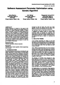
are the phased array antennas [4, 5] and the lens antennas [6, 7] and in particular the discrete lens antenna (DLA) [8–11]. Reflector antennas are technologically very mature but nevertheless have very serious drawbacks and, in particular, for feed cluster packing problems it is impossible to generate all the required beams with a single reflector. Direct radiating arrays might still be unfeasible due to the very large and complex feeding network. DLA, on the other hand, looks very promising. Lens antennas are exactly equivalent to optical lenses and are basically designed according to the geometrical optics (GO) principles. The optical ray paths which impinge on the lens propagate according to Snell’s law of refraction and wave fronts are reconstructed according to the various different ray lengths within and outside the lens. In a discrete lens antenna, on the other hand, pairs of elementary antennas are placed one on each face of the lens and interconnected via a transmission line. The rays impinging on a face are received by an antenna and the signal is transferred to the corresponding antenna on the other face via a transmission line. The lens effect of focusing the rays is re-created with appropriate lengths in the transmission lines (Fig. 1). By appropriately bending this line the two surfaces of the lens might indeed be made flat. DLA can be made perfectly flat and can be realized with mature technologies like those of microwave planar circuits. Interesting DLA applications in which the elementary radiators are patches are present in literature [8–11]. Furthermore DLA exhibits additional degrees of freedom, which have no correspondence in reflector antennas and dielectric lenses, which allows building feed clusters generating all the required beams through a single lens, hence reducing the number of antennas on the satellite. This characteristic is mainly due to the fact that interconnected elements on the two faces of the lens need not to be at corresponding points on the faces (Fig. 1). Figure 1 shows the basic layout of a DLA. It comprises two arrays of N elements, one on the fore, or radiating, side, pointing to the Earth, and one on the back, or feed, side, where the focal plane array of feeds is located. Each element on one face is linked to a corresponding element on the other face. For what concerns the focal plane cluster of feeds some results with 1, 3 or 7 horns are reported in [12], where it is also shown how the single beam gain can be augmented by using more horns and maintaining the same lens aperture. It is important to note that discrete lenses can be made active (ADLA - Active DLA) by embedding active elements (low noise amplifier - LNA; power amplifier - PA) within the lens and between each pair of radiating elements. This configuration is not only efficient
338
Agastra et al.
A2
B1 A1
B2
B2
A1 A2
Feed side
B1 Delay lines
Radiating side
Figure 1. Synoptic of a discrete lens array. but also fault-tolerant [13]. To reduce the lens dimension and to augment its performance we need efficient radiating elements to build the lens arrays. Technologically the easiest radiating elements providing good electromagnetic characteristics are the horn antennas. Horns are the most used feeders for reflector and lens antennas, and can be also used as elements in directly radiating arrays. In this latter case they are usually quite directive so as to minimize the number of elements of the array yet obtaining the desired gain. A requirement which is particularly critical in DLA is the aperture efficiency, which must be the highest possible so as to better exploit the lens surface. There are several kind of horns, square, rectangular circular, etc., the square looks the best for packing it tightly on a lens yet maintaining dual polarization capabilities. Furthermore horns can be smooth walled or corrugated. These latter are usually more appealing for cross-polarization levels, but they need thick walls to accommodate corrugations and hence cannot be tightly packed. An overview of hard e soft horns and their possible applications can be found in [15]. In this paper a smooth walled square horn will be design to achieve maximum efficiency. This requires to design horn walls so that higher order modes are excited and combined at the horn aperture to attain a field as uniform as possible. In the following section the relative amplitude an phase of the modes leading to the highest field uniformity are derived. Section 3 presents the horn geometry and Section 4 the mode matching analysis technique and the genetic algorithm optimizer used to achieve the required modal amplitudes and phases. Finally Section 5 will present optimization results and Section 6 will draw some conclusions.
Progress In Electromagnetics Research, PIER 83, 2008
339
2. DETERMINATION OF APERTURE MODAL CONTENT Is well known that, to attain maximum aperture efficiency along the bore-sight direction, the transverse electric field at the radiator aperture Eap t , should be uniform in amplitude and in direction: ˆ Eap t = E0 c
(1)
The electric field distribution at the horn aperture can be written as a series of modes: Eap t =
∞ � � TE TE � Vp ep + VpT M eTp M
(2)
p=0
being VpT E e VpT M are the modal amplitudes of the TEz and TMz modes, respectively, and eTp E and eTp M are the corresponding normalized transverse modal field distributions. Being the modes an orthogonal basis for the space of the solutions of Maxwell equations, and considering a square horn aperture, is possible to obtain the amplitudes of all modes, given a desired or computed field distribution [16]. Anyway, for electric field which is uniform in direction no TMz modes can be present. In this hypothesis (2) becomes: Eap t
=
∞ �
� � � � � TE (x) Vm,n x sin βn(y) y x ˆ cos βm
m,n=0
� � � � � (x) − sin βm x cos βn(y) y y ˆ
(3)
were we explicitly noted how TEz modes depends on two integer indices, rather than one, which cannot be both zero at the same time. (x) (y) a and b are the waveguide dimensions; βm , βn are the wavenumbers for the mode in the corresponding directions: (x) = βm
πm ; a
βn(y) =
πn b
(4)
If we assume that the horn is fed by a single-mode waveguide with a y-polarized electric field (TE10 ), then the birth of an x component in (3) is undesired. This implies that all TEmn modes with a nonzero n are undesired and that, in (1), cˆ = yˆ. Furthermore, for symmetry reasons, if a Cartesian co-ordinate reference centred at the horn aperture is chosen, then only odd values for m are acceptable.
340
Agastra et al.
The modal amplitudes are then those representing the Fourier series of a pulse along x in the [−a/2, a/2] interval, namely: TE TE TE V10 : V30 : V50 : . . . = 1 : 1 : 1 : . . . 3 5
(5)
This permit, for a y-polarized fed waveguide of the horn, to write the aperture electric field as: � ∞
� (2i − 1) π ap TE V(2i−1)0 (z) sin Et = x y ˆ (6) a i=1
If we consider a purely theoretical analysis, by approximating the square pulse with a finite number of its Fourier harmonics the energy associated to these harmonics with respect to the total energy of the pulse can give an idea of how good the pulse is approximated. If only the first harmonic is considered (TE10 mode) then this ratio is only 81%; this means that the first harmonic carries 0.81 of the power of the square pulse. If the first two harmonics are considered (TE10 and TE30 ) then the ratio is 90%, with three (TE10 , TE30 and TE50 ) it is 93%, and with four (TE10 , TE30 , TE50 and TE70 ) it is 95%. These same theoretical considerations hold for aperture efficiency, which is represented by the same number giving the power ratio. Hence by exciting the first three modes (TE10 , TE30 and TE50 ) with the correct amplitudes given by (5) and with the same phase a maximum theoretical value of 93% aperture efficiency is possible. 3. MULTIMODE HORN GEOMETRY A very interesting dual-polarization high aperture efficiency square horn is that presented in [14]. This soft horn structure allows for an 85% to 90% aperture efficiency and a cross-polarization lower than 25 dB. The creation of the desired higher order mode, and the suppression of the undesired, is controlled in [14] via the two abrupt step discontinuities, (Fig. 2). To obtain a propagating TE30 mode the first discontinuity must widen the waveguide up to at least 1.5λ, while, for the TE50 , the second discontinuity must widen up the waveguide up to at least 2.5λ. A similar horn structure has also been presented in [18]. To achieve dual polarity the steps must be present, and identical, on both planes. This inevitably leads to the birth of TE12 and TM12 modes, at the first discontinuity (Step-1), both of which with lower cut-off with respect to TE30 and hence propagating. These modes are of course unwanted and the second discontinuity (Step-2) is also
Progress In Electromagnetics Research, PIER 83, 2008
Step-1
TE10
TE10 TE30 TE12 TM12
341
Step-2
TE10 TE30 TE50
Figure 2. Two-step high efficiency horn geometry, after [14]. designed so as to generate again these two modes but with a suitable phase difference, and the same amplitude, so that the two pair of modes reciprocally cancels out. The optimization of such a structure is hard since the number of degrees of freedom on which to optimize is limited, and the recombination/cancellation of modes depends on the discontinuity distance in terms of wavelength, hence high efficiency and low cross-polarization can be attained only on a relatively narrow band. The aperture size is bound to the number of elements required to cover the whole lens surface. Small horns need to be large in number; large horns can be relatively few. Hence using large horns is advantageous economically. Furthermore, larger horns allow for a higher number of modes at the aperture, hence a greater efficiency, but the task of controlling a large number of modes is very demanding and this poses an upper limit to dimensions. If the horn is 4.5λ or less this technique is feasible since the TE50 mode is the highest propagating mode. Horns with apertures larger than 4.5λ, might propagate also the TE70 mode, possibly achieving higher efficiencies, but will also propagate other unwanted modes, so at least another step is required to keep these further modes under control, leading to an even more difficult design and narrower bands. As already mentioned, the geometry in [14] is inherently narrow band, since it relies on the distance between the two abrupt discontinuities to cancel out undesired modes. To attain better performance on a wider band we will resort in this paper to slope only discontinuities, which allows for a softer transition and birth of desired modes (Fig. 3). It can be shown that the ratio between slope angles allows obtaining the desired amplitude of the modes [17].
342
Agastra et al.
θ3
θ2 θ1
a0
L0
L1
a1
ap
a2
L2
L3
L4
Figure 3. Horn profile with a view of the angle meaning. 4. ANALYSIS AND OPTIMIZATION The parameterized geometry in Fig. 3 is optimized by resorting to a genetic algorithm technique. Genetic algorithms are stochastic search techniques that guide a population of solutions towards an optimum using the principles of evolution and natural genetics [19]. In recent years, genetic algorithms have become a popular optimization tool for many areas of research, including electromagnetics [19–27]. Both a proprietary GA-based optimizer [20–24] and the internal Matlab GA toolbox will be used here. Both implement a standard GA exploiting elitism. The fitness function the GA has to maximize is evaluated on the numerical results attained via a proprietary [21, 22] full-wave Mode Matching-based (MM) solver [28–32]. This optimization problem is particularly tough also because the design parameter of the problem (geometrical dimensions) are fewer than the constraints (amplitude and phase of all generated propagating modes - TE10 , TE30 , TE50 and undesired TE12 , TM12 plus eventual other higher modes generated at the second discontinuity). This leads to a family of nearly-optimal solutions rather than a single optimal one or, in other words, to many local maxima of the fitness function. This calls for a stochastic procedure able to avoid local maxima as the aforementioned GA. The Horn has to be decomposed into rectangular waveguide sections as in Fig. 4 for the MM to be appliable. In the figure it is evident how the slanted walls are staircased. These steps must be short and narrow so as to approximate well the smooth slanted walls without introducing a real abrupt discontinuity. Waveguide sections are 20/λ0 long, as suggestd by common practice [24]. The fitness function to be maximized is the average aperture efficiency on the desired band. This fitness function calls a very
Progress In Electromagnetics Research, PIER 83, 2008
343
Mode Matching (a) Structure
a1
a0
ap
a2 Real structure (b)
L0
L1
L2
L3
L4
Figure 4. Horn longitudinal section: (a) equivalent, approximated, structure, which can be solved via the MM; (b) real structure. efficient FORTRAN MM code to evaluate the horn electromagnetic characteristics [21, 22]. Within the fitness function, from the gain evaluated from the MM subroutine, it is possible to obtain the aperture efficiency: ef f =
λ2 G 4πA
(7)
and to average it over the band of interest. The horn return loss is not explicitly included in the fitness function since the allowable parameter ranges for the horn throat are selected, according to our experience, so as to have a good horn matching. This will of course be verified a posteriori. For what concerns the other GA details, results presented in the following are attained over a population of 20 members and on at least a 300 generation. Each gene of the chromosome represents one of the geometrical parameters which are let to vary. In particular, only a1, a2, L1, L2, L3 and L4 (Fig. 4) are inserted in the chromosome; a0 is fixed and matches the dimensions of the standard feeding waveguide and the aperture size ap is fixed too for lens packing issues. The variation range of transverse dimensions (a1 and a2) is set so that that they are always smaller than the aperture dimension (which is ap wavelengths) and greater than the smallest dimension that permit the propagation of the desired mode at each pertinent section. These, as well as the number of bits used in the discretization are summarized in Table 1, were λ0 is centre-band wavelength.
344
Agastra et al.
Table 1. GA parameters. Quantity
min
max
bits
a1 a2 L1 L2 L3 L4
1.5λ0 2.5λ0 0.7λ0 0.2λ0 1.0λ0 (2ap − 4)λ0
apλ0 apλ0 2.7λ0 2.2λ0 3.0λ0 2apλ0
5 5 5 5 5 5
Table 2. Transverse and longitudinal normalized dimensions [λ0 ] of each horn section for the two structures. Horn
L1
L2
L3
L4
a0
a1
a2
ap
3λ0 × 3λ0
2.115
1.238
2.164
2.842
0.667
1.98
2.922
3
4λ0 × 4λ0
2.149
1.528
2.904
5.311
0.667
2.193
3.442
4
5. NUMERICAL RESULTS As a first test case for the geometry and optimization technique, a horn structure with a 3λ0 × 3λ0 aperture and one with a 4λ0 × 4λ0 aperture are considered so as to compare with results in [14]. The normalized dimensions, with respect to the wavelength, obtained from the optimization process are presented on Table 2. Figs. 5 and 6 show both the attained efficiency and the return loss for the two cases on a 20% band around the design normalized frequency. It is apparent from these figures that the first horn structure (3λ0 × 3λ0 ) presents an aperture efficiency better than 85% all over the band with a mean aperture efficiency of 90.2% and a maximum of 92.24% that is closer to the theoretical value of 93%. The return loss is everywhere better than 26 dB, validating the assumption of the previous paragraph. The second horn structure (4λ0 × 4λ0 ) has an aperture efficiency better than 84% all over the band with a maximum one of 90.72%. Both horns present better electromagnetic performances than the equivalent one with abrupt discontinuities presented in [14] and, even more important, shows an efficiency which has smaller variations over the band of interest. The price to pay lies in the relatively longer horn attained, as Fig. 7, reporting the horn profiles, shows. The actual aperture dimensions of the horn are set by the specific
Progress In Electromagnetics Research, PIER 83, 2008 (a)
(b)
0
95
-10
85
-20
75
-30
65
-40 0.9
Ap.ef f.[%]
Mag.[dB]
ap =3 λ
345
55 1.1
0.95 1.05 1 NormalizedFrequency
Figure 5. Aperture efficiency and return loss of horn structure with a 3λ0 × 3λ0 aperture dimensions: present paper (a) and reference [14] (b). Bullets are relative to Ansoft HFSS simulation results. (a)
(b) 95
-10
85
-20
75
-30
65
-40 0.9
0.95 1.05 1 Normalized Frequency
Ap. eff. [%]
Mag. [dB]
ap = 4 λ 0
55 1.1
Figure 6. Aperture efficiency and return loss of horn structure with a 4λ0 × 4λ0 aperture dimensions: present paper (a) and reference [14] (b). application, in our case the DLA application. In particular, for the DLA case, for a given lens dimensions the larger the horns are, the fewer of them are needed to cover the lens, and the more economical the design is. In the following three different fixed dimension of the aperture will be chosen for the horn optimization: 60 × 60 mm2 (3.75λ0 × 3.75λ0 ), 70 × 70 mm2 (4.375λ0 × 4.375λ0 ), and 80 × 80 mm2 (5λ0 × 5λ0 ), central frequency being 18.75 GHz. The genetic optimization described earlier leads to the geometrical
346
Agastra et al.
Aperture [λ]
2.5 (a) 0
3
6
12
9
15
(b) 2.5
Normalized Length [λ]
Figure 7. Longitudinal horn profile with a physical aperture of 3λ0 × 3λ0 (dotted line) and 4λ0 × 4λ0 (solid line): (a) present paper (top half); and (b) reference [14] (lower half). Aperture [mm]
40 20
(a) (b) (c)
0 -20 -40 50
0
100 150 Length [mm]
200
250
Figure 8. Longitudinal horn profile for the three horns in Table 3. dimensions reported in Table 3. The profiles are sketched in Fig. 8, while Fig. 9 shows a typical convergence curve for the GA, in particular that for the larger horn (80 × 80 mm2 ). Table 3. Transverse and longitudinal dimensions [mm] of each horn section. Horn
L1 2
L2
L3
L4
a0
a1
a2
ap
(a) 60×60 mm
26.285 17.847 32.968 80.232 10.668 31.9
(b) 70×70 mm2
24.258 18.28 41.538 104.016 10.668 32.6 53.853 70.0
48.25 60.0
(c) 80×80 mm2
22.132 18.314 39.447 132.02 10.668 32.65 54.32 80.0
Concerning the geometry one must note that an increase in the aperture size varies significantly only the length of the last section (Fig. 8). This behaviour indicates that the sizing of the previous three sections is the correct one to obtain the desired amplitude and phase for each mode at least until after the second discontinuity. The proper amplitude development is obtained from the slant
Progress In Electromagnetics Research, PIER 83, 2008
347
95
Fitness
85 75 Best fitness Mean fitness
65 55 0
50
100
150 Generation
200
250
300
Figure 9. Performance graph of the optimization process, searching for the best aperture efficiency. variation at each section compared to the previous section. The appropriate phase is achieved by the mutual distances between the sections themselves. Hence an increase of the horn aperture maintaining the slant angle of the horn walls that permit to obtain the wanted mode amplitudes, leads automatically to a length increases of the last section. By increasing the path each mode has to travel within the last section of the horn, and considering that the wavenumbers of the modes are different, it is easy to comprehend how phase matching at the aperture deteriorates. This behaviour leads to a non-perfect satisfaction of the requirements of phase matching and consequently to a distribution of electromagnetic field on the horn aperture that gets worse as the horn length, and hence aperture size, increases. Table 4. Comparison between the three designed horns. Efficiency [%]
Horn Min (a)60×60mm2
83.56 @
Av. 88.36
16.87 GHz (b)70×70mm2
83.24 @ 79.02 @ 16.87 GHz
90.56 @
S11
CX [dB]
Length
[dB]
@ 19 GHz
[mm]