regular data transmission, and performance degradation. In this paper, we describe the implementation of BLR on a GNU/Linux platform comprising laptops equipped with. 802.11b ..... bors, and recovery is left to TCP or the application. This.
GNU/Linux Implementation of a Position-based Routing Protocol Marc Heissenb¨uttel, Torsten Braun, Tobias Roth, Thomas Bernoulli Institute of Computer Science and Applied Mathematics University of Bern 3012 Bern, Switzerland {heissen, braun, roth, bernoull}@iam.unibe.ch
Abstract The Beacon-Less Routing protocol (BLR) is a positionbased routing protocol for mobile ad-hoc networks that makes use of location information to reduce routing overhead. However, unlike other position-based routing protocols, BLR does not require nodes to periodically broadcast hello messages and thus avoids drawbacks such as extensive use of scarce battery-power, interferences with regular data transmission, and performance degradation. In this paper, we describe the implementation of BLR on a GNU/Linux platform comprising laptops equipped with 802.11b WLAN cards and GPS receivers. We present results of BLR’s performance obtained from laboratory experiments, which were conducted to validate the implementation for future planned outdoor experiments.
1 Introduction In position-based routing protocols forwarding decisions are solely based on location information. Each node is aware of its own position, e.g., through GPS, and of its immediate one-hop neighbors by the periodical broadcast of hello messages. Additionally, a location service is required that allows determining the position of the destination node, e.g., GLS [1]. Each node simply forwards a packet to a neighbor which is closer to the destination until the packet eventually arrives at the destination. Many position-based routing protocols have been proposed such as GFG [2], GPSR [3], GOAFR [4]. An overview can be found in [5]. A major drawback of those protocols is the proactive transmission of hello messages which uses scarce network resources such as battery power and bandwidth. Recently, the Beacon-Less Routing protocol BLR was proposed in [6] based on a new routing paradigm enabled by the broadcast property of the wireless propagation medium. Unlike all other routing protocols, forwarding decisions are not taken at the sender of a packet, but in a completely dis-
tributed manner at the receivers. A sender does not have to be aware of its neighbors and consequently nodes do not have to proactively transmit hello messages (beacons) as in other position-based protocols, which also saves scarce network resources like battery energy and bandwidth. The performance and the behavior of BLR was studied analytically and by simulations in [6]. Results show that BLR provides efficient and robust routing in highly dynamic ad-hoc networks and is immune to topology changes. Therefore, BLR is especially suited for vehicular and sensor networks with frequently changing topologies. The promising results are the motivation to go a step further and implement the protocol in a real testbed. We developed a prototype system and conducted measurements to obtain more insight on the protocol’s performance and behavior in a real world environment. In Section 2, we briefly review the BLR protocol and describe its main features. Afterwards, the implementation on a GNU/Linux platform is presented in Section 3 and encountered real world challenges are discussed in Section 4. Section 5 describes the experimental setup and provides measurement results. Finally, Section 6 concludes the paper.
2 Beacon-Less Routing Protocol (BLR) Unlike other position-based routing protocols, BLR does not require the periodic broadcast of hello packets. BLR selects a forwarding node in a distributed manner among all its neighboring nodes without knowing the existence or positions of neighbor nodes. BLR has three main modes of operation; greedy mode, backup mode, and unicast mode.
2.1 Greedy mode Packets are routed in greedy mode whenever possible because only in this mode BLR is really stateless and does not require the transmission of hello packets, i.e., nodes are normally not aware of any neighboring nodes. Therefore, when a node has to send a packet it simply broadcasts the packet.
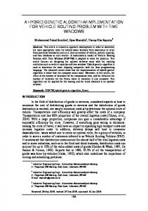
Consequently, all neighbors receive the broadcast packet. The protocol ensures that just one of the receiving nodes relays the packet further. This is accomplished by different forwarding delays and restricting the nodes that are allowed to forward the packet to a certain area, called forwarding area. Nodes within this area can mutually receive each others transmissions. For the forwarding area BLR uses a circle with diameter r relative to the forwarding node S in the direction of the final destination D as depicted in Fig. 1. A Forw arding Area
r
B p
S
D A
2.2 Backup Mode If no node is located within the forwarding area, greedy routing fails. This is detected if a node does not overhear a further rebroadcast within M ax Delay of its previously broadcasted packet. This node forwards the packet via unicast further in backup mode. Therefore, the node broadcasts a request for a beacon packet. All neighbors that receive this packet reply with a beacon indicating their positions. The packet is then forwarded to the replying node that is closest to the destination. If none of the neighbors is closer to the destination than the requesting node, the packet is routed according to the face routing algorithm based on the ”righthand” rule, a concept known for traversing mazes, on the faces of a locally extracted planar subgraph, see for example GOAFR [4] for more details. As soon as the packet arrives at a node closer to the destination than where it entered backup mode, the packet switches back to greedy mode.
C
2.3 Unicast Mode Figure 1. Forwarding Area with potential forwarders A and B receiving node can determine if it is within the forwarding area from its own position and the positions of the destination D and the previous node S. Both positions of S and D are stored in the packet header. Nodes in the forwarding area are called potential forwarders, e.g., A and B in Fig 1. Potential forwarders calculate a Dynamic Forwarding Delay (DFD) in the interval [0, M ax Delay] depending on their position relative to the previous and the destination node. The DFD is calculated by (1) with r as the transmission radius of a node, p the node’s progress towards the destination, and M ax Delay as a system parameter. Nodes outside the forwarding area simply drop the packet (node C). µ ¶ r−p Add delay = M ax Delay · (1) r According to this DFD function, the node with the most progress (e.g., node B), i.e., closest to the destination, calculates the shortest Add Delay and thus rebroadcasts the packet first. The other potential forwarders (e.g., node A) overhear this further relaying and cancel their scheduled transmissions of the same packet. The rebroadcast packet is also received by the previous transmitting node and acknowledges the successful reception at another node. Simultaneously, the neighbors of the rebroadcasting nodes also received the packet and they determine if they are within the forwarding area relative to node B and destination D. Potential forwarders calculate an Add Delay and compete to rebroadcast the packet again.
Routing in greedy mode makes BLR susceptible to packet duplication as data packets are broadcast over multiple hops. Packet duplication occurs for each node in the forwarding area, which does not detect that a packet was already rebroadcast. In reality, there are many reasons that prevent nodes from successfully receiving the rebroadcast packets such as irregular transmission ranges, obstacles, and simultaneously on-going transmissions in the vicinity. BLR implements the unicast mode to minimize the number of duplicated packets. After a node has detected that another node has rebroadcast the packet, it is also aware of the forwarding node’s position. Thus, the node may send the subsequent packets to the same destination via unicast to the node which relayed the broadcast packet. Due to the mobility of the nodes, nodes located at a better position may enter into the node’s transmission range. In order to be able to detect these new nodes, a packet is broadcast in greedy mode after a certain time again such that potential forwarders compete to rebroadcast the packet.
3 Implementation 3.1 Overview The target platform of the implementation is GNU/Linux. We used Gentoo Linux [7], although any other GNU/Linux distribution based on Linux 2.6 will work for our implementation. We integrated BLR within the protocol stack as depicted in Fig. 2, i.e., between the IP and the link layer. Therefore, it is transparent to the upper layers and applications. Consequently any application such as HTTP, ssh, ping and also ICMP can run unmodified.
The BLR protocol was however implemented in the user space of Linux due to simplicity reasons. Therefore, outgoing packets (solid line) have have to be intercepted and processed accordingly before being passed to the wireless network adapter. More specifically, we introduced a virtual interface tun0 provided by the tuntap [8] device. A new route that redirects all traffic to the BLR network (private destination IP-Addresses 10.0.1.0/24) through tun0 is added to the system routing table. Consequently, Internet traffic is not affected by the BLR application and routed as normal directly to the 802.11 interface. By listening on tun0, the BLR application can catch all traffic sent to the BLR network and inserts the BLR header and updates the IP header. Afterwards, packets are sent via the pf_packet facility, which allows the sending of Ethernet and IP packets directly to the 802.11 network adapter. Incoming packets (dashed line) are passed User Space
BLR
Application
TCP/ UDP IP pf_packet
tun0-I f.
802.11
has to be blocked somehow. This is achieved by deploying the IPtables [9] packet filter right after the pf_packet facility. This filter blocks all incoming traffic that has the protocol number of BLR set in the IP header. For broadcast packets, this blocking would not be necessary since the kernel simply drops broadcast traffic with a protocol number for which there is no open socket. However, when the kernel receives unicast traffic with an unknown protocol number, it sends an ICMP destination unreachable message back to the sender, which has to be avoided.
3.2 BLR Application The BLR application is split into three separate processes as depicted in Fig. 3. The main process receives/sends the packet from/to the localhost/network, transforms and updates headers, calculates the Add Delay, and manages packet timeouts, unicast route information, as well as a list of duplicate packet IDs. The GPS process is connected to an external GPS device and provides location information. The sendqueue process receives outgoing packets together with the calculated Add Delay from the main process and sends the packet after the indicated delay. If the main processes receives a packet from pf_packet, it calls the sendqueue process in order to determine if the packet is queued for transmission. If so, another node forwarded the packet first and the sendqueue process can remove the packet from the queue. The size of the BLR header is 32 bytes and has the following fields.
Kernel
• Packet type (1 byte): Data, Location request, LocationReply, Request for beacon, Beacon.
Figure 2. Implementation of BLR in the protocol stack
• Original protocol (1 byte): Protocol number of TCP, UDP, ICMP, etc. This corresponds to the protocol field in the IP header, because the BLR header is inserted between the IP and transport layer header.
over pf_packet to the BLR application and are either forwarded to the next hop or passed to localhost, depending on the destination address in the IP header. When packets are forwarded, the BLR application only updates the BLR header and additionally delays the packets by the newly calculated Add Delay before the packets are passed again via pf_packet to the network adapter. On the other hand, when the packet is destined for this host, the BLR header is stripped off and the IP header modifications done by the BLR application at the sender are reversed. Afterwards, the packet is forwarded through the tun0 to the application. A problem occurs because pf_packet actually creates a copy of all incoming packets. One copy is passed to the BLR application, while the original packet is passed to the kernel and from there to the application. The original packet
• Sequence number (2 bytes): This number together with the source address allows to unambiguously identify a packet. • Backup distance (4 bytes): This field is used to indicate the distance to the destination from where greedy routing failed, which is required in order to determine when to switch back to greedy routing. • Position information (8 bytes each): Position of the previous, source, and destination node. The previous and destination node positions are required to calculate Add Delay. The source node’s position is used to update location information at the destination in case of bidirectional traffic. In the following, we describe in more detail the processes and how packets are handled.
WLAN
• The packet length fields needs to be increased by the size of the BLR header.
pf_packet tun0-I f.
main tun0-I f.
localhost
localhost Position/ Time
GPSrecv.
GPS
• The protocol field is changed to 254, which we used for the BLR protocol. The original protocol number is stored in the BLR header. • Finally, the header checksum needs to be recalculated.
sendqueue
pf_packet
WLAN
serial ( NMEA)
Figure 3. Running processes in the BLR application
GPS Process The GPS process is connected to an external GPS device, which it polls for changes in location information. It parses the GPS data and passes position updates to the main process. The connection is established through an RS-232 interface and the GPS information is transferred with the NMEA-0183 protocol [10] from the GPS receiver to the laptop. Sendqueue Process The sendqueue process is responsible for queuing the packets according to their respective dynamic forwarding delay. It receives packet/delay tuples from the main process and maintains an ordered list of all pending packets. When the associated timer expires, the packet will be sent to pf_packet. The sendqueue is implemented separately from the main process since it its only tasks are to manage packet delays and to queue and send packets. The sendqueue further handles the deletion of packets from the queue, whenever the main process detects that another node has already forwarded a pending packet. Main process This is by far the most complex process and is responsible for switching packets between components, management and coordination of the other components, execution of the BLR functions, etc. When the main process receives an IP packet through tun0, it inserts the BLR header and updates the IP header. Changes are necessary in four IP header fields. • The source address needs to be changed from the IP address of the tun0 interface to the IP address of the outgoing interface.
Furthermore, the main process calculates Add Delay and forwards this along with the packet to the sendqueue process. It also maintains a hosttable to store information about known destinations, namely their most recent positions and the next hop to reach them if unicast mode is used. The packetlist caches packets that have been sent and have not yet been acknowledged, together with a timeout value for each packet. packetlist also handles retransmissions in case of timeouts. Whenever BLR has to switch to backup mode, it takes some time until the next hop is determined due to the sending of the beacon request packet and the time until the beacons from the neighbors are received. The backupqueue caches outgoing packets that have to wait to be forwarded until the backup mode setup is completed.
4 Challenges In this section, we briefly review the main challenges we faced during the implementation in the Linux testbed as opposed to the previous implementation in the simulator.
4.1 Location Service Location services that provide the position of nodes is a research aspect in itself and several solutions have already been proposed (see [5] for an overview). Therefore, a common assumption of most position-based routing protocols is that the position of the destination is somehow known. In the network simulator, it can be implicitly assumed that this position information is available. In reality, we have to implement a mechanism that provides the position. As it was not our goal to implement a fully functional location service and it would not be appropriate for a small testbed with a few laptops, we chose to implement a simple request-reply mechanism based on flooding. The request and the reply with the geographical position are piggybacked on data traffic whenever possible. In case of unidirectional traffic, position information is invalidated periodically, and the source broadcasts a new location request. In case of bidirectional traffic, or simply if TCP is used, destination locations are not invalidated, but the position can be simply extracted from packets returning from the destination, namely from the source field in the BLR header. Thus, the overhead can be reduced to the initial flooding of one location request packet in case of bidirectional traffic.
4.2 Duplicated Packets
4.5 Interrupt granularity
The objective of the unicast mode is to reduce the number of duplicated packets. However, still transmissions are broadcast over intermediate hops. In ideal conditions of a network simulator, radio propagation is modeled by simple isotropic transmission ranges. In reality however, we observed many duplicated packets due to irregular transmission ranges. Therefore, we additionally implemented a filtering mechanism. Each node compares the uniquely identifying source address and sequence number of a packet against a table containing the recently received and also overheard packets. If this packet is a duplicate of a previously received or overheard packet, the node broadcasts a control packet suppressing the further forwarding of that duplicated packet by its neighbors. Therefore, the duplicated packet can be again disposed.
The M ax Delay can be chosen in the order of some milliseconds based on the experienced network simulator results. Basically, M ax Delay indicates the range over which potential forwarders schedule their retransmissions. The Linux kernel has a limitation that severely affects the possible value of M ax Delay, namely the granularity of the timer interrupts. This granularity is defined by a compile-time kernel constant called HZ. On Linux kernels 2.6 or newer, this constant is set to 1000 resulting in timer interrupts every 1 millisecond. (In kernel 2.4 and older, the HZ was set to 100). This means that the select() system call returns at 1 millisecond intervals only. Consequently the granularity of Add Delay is also only 1 millisecond. Therefore, a rather long M ax Delay has to be chosen to reduce the risk that all nodes transmit simultaneously and limit the usefulness of the DFD concept. In [6], it was proposed to set M ax Delay = 2 ms based on simulation results, which is definitely too short for the Linux implementation. However, the longer M ax Delay also increases the end-to-end delay. While possible in theory, a further increase of the HZ value is not yet completely supported by the Linux kernel. Even if possible, increasing HZ also increases the overall timer overhead, because more timer interrupts are generated. This may not be an issue for our testbed where no other applications are running, but definitely it will be an issue for small mobile devices with limited computation resources.
4.3 IP Fragmentation The BLR header is part of the IP payload in the current implementation. Thus, if fragmentation occurs, only the first IP fragment will contain the BLR header. The header is however required to route packets by BLR. Subsequent fragments will not contain the BLR header and will simply be dropped, because nodes do not know how to process them. Therefore, IP fragmentation has to be avoided. To achieve this, the MTU of the virtual tunnel interface is decreased by the size of the BLR header, which is inserted before Transport layer header, in order to avoid fragmentation at the source node. Additionally the DF (Don’t Fragment) bit is set in the IP header such that intermediate nodes do not fragment the packet. PMTU (Path MTU) discovery is used to handle links where the standard MTU is too large.
4.4 MAC layer control If a unicast packet is not acknowledged, the 802.11 MAC layer retransmits a packet up to seven times before giving up. In the network simulator implementation, the MAC layer can signal a failed transmission to the upper layer, which in turn selects another next hop and passes the packet again to the MAC layer. This mechanism is also applied by BLR [6] and GPSR [3]. Without this optimization, many unicast packets would be dropped due to unreachable neighbors, and recovery is left to TCP or the application. This severely decreases network performance as retransmissions are end-to-end and not link retransmissions. In a Linux implementation of BLR with WLAN cards however, the MAC protocol is largely implemented in the firmware of the 802.11b card, which makes accessing the mentioned functions in today’s card nearly impossible.
5 Experiments 5.1 Equipment and Configuration The testbed consists of 5 laptop computers running Linux 2.6. Each laptop is equipped with an IEEE 802.11b WLAN cards. The cards are configured to run in ad-hoc mode without RTS/CTS, i.e., the DCF of 802.11b is used, and the data rate is set to 2 Mbps. The hardware equipment is heterogenous, i.e., the laptops are from different manufacturers. The same applies to the WLAN cards, some laptops have built-in cards, while other use Orinoco WLAN cards plugged in the PCMCIA-slot. Each laptop also has a GPS receiver connected via the serial RS-232 line. The GPS devices are not only used for providing positioning information to the nodes, but we also use GPS for timing information. This information is provided once per second. The GPS timing information is actually not required for the BLR protocol, but only for performance measurements. The accuracy of the information is below 5 m and 200 ns for the positioning and timing information, respectively. In this paper, we present the results from experiments that were conducted in the laboratory in order to validate
the implementation and for reference purposes, which allow a comparison with future outdoor experimental results. As the GPS receivers do not work in indoor environments, the position of the laptops had to be hardcoded to yield a virtual topology. Therefore, the positions and the distances between nodes in this virtual topology do not match the actual physical location of the laptops. Furthermore, all laptops are placed on a table within a few meters of each other and thus could physically receive all transmissions of all nodes. To ensure that a laptop only processes the packets from laptops within the transmission range in the virtual topology, a filter based on MAC addresses has been implemented. This filter operates directly on the pf_packet socket and simply drops packets from out-of-range nodes in order to match the physical and the virtual topology such that the BLR application never sees packets from virtually out of range nodes. This approach saves processing work on the side of the BLR application since the kernel does all the necessary filtering. The implementation of the MAC filter is done by means of the Berkely Packet Filter (BPF) language [11]. The GNU/Linux implementation is called Linux Socket Filter (LSF) and is compatible with the BPF language.
249m S
D
249m
249m
S
D 20m
Chain
Pairs
20m 249m
S
D
Contention
249m
Backup S
D
Figure 4. Topologies for the experiments Traffic is sent by the ping utility, which yields the round trip time RTT. For each measurement, 2000 ICMP echo requests were sent, which together with the echo replies result in 4000 total data packets. The transmission rate had to be limited to 10 echo request per second, because all nodes are physically within each other transmission range. A transmission of a node blocks all other nodes on the MAC layer, and not only the neighbors in the virtual topology. Therefore, experiments with higher data rates where a new IMCP echo request is sent out before the previous echo reply arrived back at the source do not make sense. The default packet size was set to 56 bytes. Including the ICMP, IP, BLR, and MAC header this yields 180 transmitted bytes. The experiments were conducted with a rather long M ax Delay of 5 ms and 25 ms to reduce the risk that nodes transmit simultaneously due to the low interrupt granularity as explained before in Section 4.5. The transmission range for calculating the Add Delay was set to a 250 m. Except for one experiment, we did not use the unicast mode in order to route packets as often as possible in greedy mode. We used four topologies for the laboratory experiments as depicted in Fig. 4, called chain, pairs, contention, and backup topology. Additionally, we also compared the measurements of these experiments with results obtained from simulations conducted with the Qualnet [12] network simulator and from analytical prediction. The scenarios for the simulations were identical to the experiments, specifically the network topologies and the parameters of the BLR protocol such as M ax Delay.
5.2 Chain Topology The chain topology is the most simple topology as no contention occurs and only one node always will forward the packet. The forwarding node is located at the boundary of the transmission range and almost immediately forwards the packet without introducing Add Delay. Thus, the RTT is basically independent of the M ax Delay as shown in the histogram in Fig. 5, which shows the distribution of the measured RTTs. The average is in both cases 17.4 ms and the delivery ratio was always 100%. Considering the fact that a packet pair is transmitted over eight hops (four hops from the source to the destination for the echo request and four hops back to the source for the echo reply), the measured RTT is approximately only 2 ms per hop. When we roughly estimate that 180 Bytes are transmitted over 8 hops with a bandwidth of 2 Mbps, we would expect an RTT of approximately 6 ms. The Add Delay does only contribute marginally to the RTT and is much less than 1 ms per hop, because the progress of 249 m almost equals the transmission radius. In the simulations, we measured an RTT of approximately 8 ms, which is close to the analytical estimation, considering that we did not take into account the influence of the MAC layer. However, the RTT is only about half the RTT measured in the experiments. The reason is that the Qualnet network simulator does not introduce any delay for processing packets at the nodes, i.e., the
1200
5ms 25ms
Number of packets
Number of packets
5ms mean = 29.618
1000
1000 800 600 400
800 600 400 200
200
0
-3
.0
36 -3
.0
34 -3
9
6.
9
4.
9
2.
topology
Number of packets
with
25ms mean = 83.684
1000 800 600 400 200 0
.9 90
.9 88
.0
90
.9 86
.0
88
.9 84
.0
86
.9 82
.0
84
.9 80
.0
82
.0
The results from the pairs topology are given in Fig. 6 and Fig. 7. In this topology, a packet pair is again transmitted over eight hops. However, the RTTs now vary strongly for the two different M ax Delay as expected. The two transmissions from the nodes with only 20 m progress are delayed significantly as they calculate a long Add Delay, which is close to M ax Delay according to (1). In the pairs topology, this yields RTTs of approximately 30 ms and 80 ms for M ax Delay = 5 ms and M ax Delay = 25 ms, respectively. The delay introduced by BLR is approximately three times 230 250 · M ax Delay, two times from S to D and only once from S back to D, which is approximately 14 ms and 69 ms for a M ax Delay of 5 ms and 25 ms, respectively. Together with the transmission delay of 6 ms, we obtain an expected RTT of 20 ms and 75 ms for the two different M ax Delay values. The respective measured RTTs were 21 ms and 77 ms in the simulations. These results are again approximately 8 ms shorter than in the experiments, independent of the M ax Delay, which confirms the previously stated reasons for the longer delay, namely the zero processing time at the nodes in the simulator and the interrupt granularity of the Linux implementation. In the pairs topology, we also evaluated the impact of the unicast mode. Although packet duplication is not an issue as only one potential forwarder exists, the RTT is af-
.0
Figure 6. Pairs Max Delay = 5 ms
80
5.3 Pairs Topology
9
packets can be forwarded immediately, which is definitely not the case in reality. Furthermore as mentioned in Section 4.5, the Add Delay has only a granularity of 1 ms in the experiments. This is unlike for the simulations were the Add Delay is really the calculated value and not ”rounded up” to the next millisecond.
0.
9
8.
9
9
9
9
9
9
Delay [ms]
Delay [ms]
Figure 5. Chain topology with Max Delay = 5 ms and Max Delay = 25 ms
32 -3
.0
30 -2
.0
28 9
. 20
6.
0-
. 19
0-
. 18
0-
. 17
0-
. 16
0-
. 15
0-
-2
. 20
. 19
. 18
. 17
. 16
. 15
.0
26
0
Delay [ms]
Figure 7. Pairs Max Delay = 25 ms
topology
with
fected. Recall that in unicast mode, the packets are forwarded without introducing Add Delay if the next hop is known. In Fig. 8, the histogram of the measured RTTs with M ax Delay = 5 ms is shown. The RTT is significantly shorter than when packets are always broadcast in greedy mode and is reduced from 29 ms to 16 ms. We can also see that there are some packet with longer RTTs around 25 ms. The reason is that the unicast mode switches to greedy mode every 5 s in order to detect possibly better located neighbors. Packets transmitted in greedy mode are again dynamically delayed at each node and not immediately forwarded as in unicast mode.
5.4 Contention Topology In the contention topology, three nodes receive the transmitted packet from the source node and schedule the packet for forwarding as they are all within the forward-
Number of packets
5.5 Backup Topology
5ms, with unicast mean = 16.205
1200 1000 800 600 400 200 0
-2
.0
25 -2
.0
23 -2
.0
21 -1
.0
19 -1
-1
.0
17
.0
15 -1
.0
13
9
5.
9
3.
9
1.
9
9.
9
7.
9
5.
9
3.
Delay [ms]
Figure 8. Pairs topology with unicast mode and Max Delay = 5 ms
ing area. They calculate different Add Delay however and the first transmitting node suppresses the others accordingly. In Fig. 9, the distribution of the RTTs is shown for a M ax Delay of 5 ms. The results were almost identical for M ax Delay = 25 ms due to the same reasons as for the chain topology. We can observe that the RTT is quite short compared to the previous investigated topologies because a packet pair is only transmitted over four hops (two hops to the destination and two hops back to the source). The the-
In a last experiment, we validated the backup mode of BLR. There is no node located in the forwarding area and the packets are routed in backup mode for three hops until arriving at the node closer to the destination than the source. We measured two different RTTs of approximately 40 ms and 60 ms as depicted in Fig. 10. The reason is that while the backup mode acquires neighbor information if greedy forwarding failed, i.e., during the beacon request reply dialog, other arriving packets are queued in the backupqueue. When the backup mode setup is completed and the forwarding node has determined the next hop by the “right-hand”, all queued packets are sent immediately to this next hop, thus, some packets in the queue encounter shorter RTTs. The backup mode is also stateless and does not store positions of neighboring nodes, therefore the first following packet after the queue has been emptied again has to wait until the request reply dialog is completed in order to acquire the positions of the neighboring nodes. The RTT is still quite short considering the fact that nodes have to transmit a request for beacon packet and wait until neighbors have replied. In the simulations, we measured an RTT of 51 ms which is again approximately 1 ms less delay per hop than in the experiments due to the same reasons as mentioned before. 700
5ms mean = 50.807
Number of packets
1200
Number of packets
600 5ms mean = 7.849
1000 800 600
500 400 300 200 100
400
0
9 4. -6 .0 .9 64 -62 .0 .9 62 -60 .0 .9 60 -58 .0 .9 58 -56 .0 .9 56 -54 .0 .9 54 -52 .0 .9 52 -50 .0 .9 50 -48 .0 .9 48 -46 .0 .9 46 -44 .0 .9 44 -42 .0 .9 42 -40 .0
40
200 0
49
1.
-1 49
0.
49
49
49
49
-1
.0 11
.0 10
9.
0-
9.
8.
7.
0-
8.
0-
7.
6.
0-
6.
Delay [ms]
Delay [ms]
Figure 10. Backup Max Delay = 5 ms Figure 9. Contention Max Delay = 5 ms
topology
topology
with
with
5.6 General Observations oretical transmission delay is approximately 3 ms because of the reduced hop count. Since the Add Delay is again for all nodes significantly below 1 ms, the expected RTT is around 3 ms, which matches the measured RTT of 4 ms in the simulations. The difference to the RTT of the experiments is again because of the required processing time at the laptops.
Until now, we only considered the measured RTTs in the experiments. We can conclude that the RTTs are short, are as expected, and vary only slightly around the mean. Other quantitative performance measurements are briefly discussed in the following. In all four topologies, the delivery ratio was always 100%. This is not surprising consider-
ing the fact that the nodes are physically close to each other, even if they are distant in the virtual topology. Furthermore, we observed that in the chain, pairs, and contention topology, there was approximately one packet per thousand packets transmitted unexpectedly in backup mode. The reason was that very rarely some packets showed a higher RTT and collided with subsequent transmitted packets which caused the required retransmissions in backup mode. This effect is especially obvious in the laboratory where all nodes are within transmission range. Furthermore, we observed very infrequently duplicated packets, again in the order of some few per thousand. However, they could be successfully suppressed at the next node by transmitting a control packet as described in Section 4.2. Thus, no duplicated packet arrived at the destination node. Especially for the contention topology, the few duplicated packets indicate that the first transmitting node is able to successfully suppress the other potential forwarders.
6 Conclusions In this paper, we presented an implementation of the position-based routing BLR on a GNU/Linux platform using laptops equipped with 802.11b WLAN cards and GPS receivers. The advantages of BLR are that it is stateless and does not require to have knowledge about its neighbors, which allows the disposal of the periodical transmission of hello messages and makes it immune to frequently changing network topologies. The BLR was implemented in the user space of GNU/Linux and is transparently integrated in the protocol stack, which allows to run arbitrary applications without modification. We discussed several problems encountered during the implementation and the experiments and described possible ways to solve them. BLR is implemented to retrieve position information provided by GPS receivers. Unfortunately, this information could not be used in our laboratory experiments as all laptops were within a single transmission range and a virtual topology had to be configured manually. We conducted several laboratory experiments to validate the implementation. The forwarding of the packets in the greedy, unicast, and backup mode of BLR was as expected. The results also indicate that BLR is able to deliver packet over multiple hops in a short time. Packets are forwarded reliably and the delivery ratio was always 100%. Furthermore, the forwarding nodes successfully suppressed the other potential forwarders and acknowledge also the previous node reliably, because basically no duplicated packets were observed. In a next step, we will conduct outdoor experiments and use GPS position information. In these experiments, the results may differ from the laboratory experiments because nodes may no longer be within transmission range, which can cause duplicated packets and longer RTTs. We also plan to conduct
experiments with high mobility, for which BLR was originally designed, where the laptops are transported in cars.
References [1] J. L. et al., “A scalable location service for geographic ad-hoc routing,” in Proc. of MOBICOM ’00, Boston, USA, Aug. 2000, pp. 120–130. [2] P. Bose, P. Morin, I. Stojmenovic, and J. Urrutia, “Routing with guaranteed delivery in ad hoc wireless networks,” in Proc. of DIALM ’99, Seattle, USA, Aug. 1999, pp. 48 – 55. [3] B. Karp and H. T. Kung, “GPSR: Greedy perimeter stateless routing for wireless networks,” in Proc. of MOBICOM ’00, Boston, USA, Aug. 2000, pp. 243– 254. [4] F. Kuhn, R. Wattenhofer, and A. Zollinger, “Worstcase optimal and average-case efficient geometric adhoc routing,” in Proc. of MobiHoc ’03, Annapolis, Maryland, USA, June 2003, pp. 267 – 278. [5] M. Mauve, J. Widmer, and H. Hartenstein, “A survey on position-based routing in mobile ad-hoc networks,” IEEE Network, vol. 15, no. 6, pp. 30–39, Nov. 2001. [6] M. Heissenb¨uttel, T. Braun, T. Bernoulli, and M. W¨alchli, “BLR: Beacon-less routing algorithm for mobile ad-hoc networks,” Elsevier’s Computer Communications Journal (Special Issue), vol. 27, no. 11, pp. 1076–1086, July 2004. [7] (2005, Apr.) Gentoo linux website. Gentoo Foundation, Inc. [Online]. Available: http://www.gentoo.org [8] (2005, Apr.) Virtual point-to-point(tun) devices. Maxim Krasnyansky. [Online]. Available: http://vtun.sourceforge.net/tun/index.html [9] (2005, Apr.) The netfilter website. Harald Welte. [Online]. Available: http://www.netfilter.org [10] (2002, Jan.) National Marine ics Association (NMEA). [Online]. http://www.nmea.org/pub/0183/
ElectronAvailable:
[11] S. McCanne and V. Jacobson, “The BSD packet filter: a new architecture for user-level packet capture,” in Proceedings of the 1993 winter USENIX conference, San Diego, CA, USA, Jan. 1993, pp. 259–269. [12] (2004, Nov.) Qualnet. Scalable Network Technologies (SNT). [Online]. Available: http://www.qualnet.com/