GraCAD - Graph-Based Tool for Conceptual Design Janusz Szuba1 , Andy Sch¨ urr2 , and Adam Borkowski1 1
2
Institute of Fundamental Technological Research, Polish Academy of Sciences, ul. Swietokrzyska 21, 00-049 Warsaw, Poland {jszuba, abork}@ippt.gov.pl Institute for Software Technology, University of the German Armed Forces Munich, D-85577 Neubiberg, Germany
[email protected]
Abstract. This paper proposes a new methodology for computer-aided design of layouts of buildings. The presented methodology addresses the very early phase of designing that is called Conceptual Design. In this methodology the architect does not pay attention to layout details, but operates on functional requirements, constraints, and high-level architectural concepts such as functional areas and rooms. The GraCAD system realizes this methodology by adding a high-level design tool to the wellknown commercial program ArchiCAD. This design tool has been realized using graph-based knowledge representation techniques and graph grammars as offered by the system PROGRES. Preliminary results show that the developed ArchiCAD add-on and the formalism of graph grammars seems to be useful in aiding architectural design.
1
Introduction
The main aim of this project is to create a system based on graph transformations which supports architects in the early phase of architectural design. Contrary to conventional expert systems proposed previously in this domain (compare, e.g.[8]) our system can be seen as a knowledge-based add-on for a standard CADtool. We restrict our considerations to a rather simple example of designing a single-store family house, but the methodology remains valid for designing other types of buildings. The system, called GraCAD, helps the architect to create a prototype design that fulfils a given set of high-level requirements. GraCAD is integrated with the commercial program for architects ArchiCAD [1]. The graphbased knowledge representation of family house requirements and corresponding layouts forms the theoretical background of our system. The graph rewrite tool PROGRES developed at the RWTH Aachen [15] is used to manipulate these graph representations and to translate high-level requirements graphs into lowlevel graphs reflecting the internal data structures of ArchiCAD. Pioneered by N. Chomsky [6], the linguistic approach to world modeling found applications in many areas. The core idea in this methodology is to treat certain primitives as letters of an alphabet and to interpret more complex objects
2
and assemblies as words or sentences of a language based upon the alphabet. Rules governing generation of words and sentences define a grammar of the regarded language. In terms of the world, modeling such a grammar generates a class of objects that are considered plausible. Thus, grammars provide a very natural knowledge representation formalism for computer-based tools that should aid the design. Since G. Stiny [16] has developed shape grammars many researchers showed how such grammars allow the architect to capture essential features of a certain style of buildings. However, the primitives of shape grammars are purely geometrical, which restricts their descriptive power. Substantial progress was achieved after graph grammars were introduced and developed (cf. e.g. [14]). Graphs are capable to encode much more information than linear strings or shapes. Hence, their applicability for CAD-systems was immediately appreciated [9]. A special form of graph-based representation has been developed by E. Grabska [10]. In 1996-98 Grabska’s model served as the basic knowledge representation scheme in the research reported by the third author at the conferences in Stanford [11], Ascona [3], and Wierzba [4]. It turned out that by introducing an additional kind of functionality graphs Grabska’s model one can conveniently reason about conceptual solutions for the designed object. The functionality analysis of houses as the starting point of the conceptual design has been proposed by several researchers (compare, e.g. [5], [7]). Such a methodology allows the designer to distract himself from details and to consider the functionality of the designed object, the constraints and the requirements to be met, and the possible ways of selecting optimum alternatives more clearly. The results described in Sections 2 to 4 can be viewed as the further development of the research reported previously in [17], [18], and [19]. The novelty is twofold. First, an intermediate functionality graph has been inserted between the initial specification of the project and the decomposition graph (former CP-graph). Second, the PROGRESS transactions allowed us to implement rule checkers that were missing in the previous versions of software.
2
Early Phase of Designing - Conceptual Design
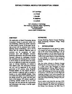
This section concerns the early phase of designing called conceptual design. This is the phase when the architect, knowing functional requirements and constraints from the conversation with the client, sketches the layout of the building (compare the part of Fig.1 above the horizontal line and Fig. 2). These sketches, prototype designs, are presented to the client and discussed with him. Finally, one of the created prototype designs becomes the basis for the complete design (compare, e.g. [12] or [13]). Rapid prototyping is important in many areas and architecture is no exception. It enables the designer to present the draft of the design to the client in short time and to achieve approval or disapproval of the presented proposition. The scheme given in Fig.1 is deliberately simplified. The real design process includes repetitive loops, abandoning partial solutions and backtracking.
3
The aim of this scheme is merely to emphasize the role of sketching conceptual alternatives at the initial stage.
Designer's Conversation With Client About Designed Object Specifying Functional Requirements And Constrains
Sketching Skeleton Design
Sketch 1
Sketch 2
Sketch 3
.......
Sketch n
------------------------------------------------------------------------------------------------------Some Design Tasks
Complete Design
Fig. 1. Activity diagram of design process
Fig. 2. Use case diagram for architectural design
3
GraCAD - Aiding Conceptual Design
GraCAD aids the phase of designing described in the previous section. Our system helps architects rapidly creating prototype designs for given functional requirements and constraints. Using GraCAD, the architect works on the level of functional areas and rooms. He does not operate on the level of detailed geometrical descriptions of the regarded object, a house: exact coordinates and dimensions would distract him from conceptual thinking. The architect avoids details not important in the conceptual phase of designing. GraCAD is equipped with a set of functions aiding in rapid prototyping:
4
– – – – – –
checking if specified functional requirements are coherent, sensible checking if the created design fulfils specified functional requirements checking if basic architectural norms are not violated in the design automatically inserting windows and doors adjusting the rooms to the chosen contour of the house generating standard solution layouts
In the following subsections of this chapter details of using the system are presented. 3.1
Basic parameters
The first step is to specify the basic functional requirements for a designed object. As mentioned before, we restrict our consideration to designing a single-store family house. The functional requirements for such a house are straightforward: – number of inhabitants – total area of the house – functional areas of the house The user specifies the basic parameters by filling the form shown in Fig.3a. 3.2
Functionality graph
The next step is to specify the functionality of the house. This is done by drawing a functionality graph (Fig. 3b). The nodes of this graph represent areas that are supposed to carry out specific functions. The edges describe relations between such areas. For example, the edge AreaAccess between the areas a1 and a2 indicates that the area a1 is accessible directly from the area a2 . In this way the user specifies the accessibility of the areas. 3.3
Decomposition graph
The next step is to map functional requirements to rooms. Fig. 4a shows GraCAD in the mode of drawing the decomposition graph of the building. Each node of this graph represents a room of the designed house, an edge RoomAccess between two rooms indicates that one room is accessible directly from the other. Above each node a list of the room functions is displayed. Thus, creating the decomposition graph, the user specifies simultaneously the accessibility and the function of each room. 3.4
Room editor
After specifying the functional requirements (steps 1-3) the architect starts to work on the prototype design that matches defined functional requirements. Fig. 4b shows the module Room Editor that is used to create a prototype floor layout.
5
Fig. 3. GRACAD a) Input form for basic parameters b) Functionality graph
Fig. 4. GRACAD a) Decomposition graph b) Rooms before adjustment
Fig. 5. GRACAD - Rooms after adjustment
6
The top window displays the elements that should be assembled like windows, doors, house contour and the rooms from the decomposition graph. The bottom window shows the top view of the floor layout. How the prototype design is created? First, the architect chooses the house contour element from the top window, drags it and drops in the bottom window. The square contour of the house (dark walls) appears in the bottom window. The total area of this contour is specified by the basic parameters entered in the first step of the design process. Then the architect can modify the shape of the contour. In the present version of GraCAD only rectangular rooms and contours are allowed. In the next step the rooms are created. The user chooses the room from the top window, drags it and drops in the bottom one. The place in the bottom window, which the user pointed out, becomes the center of the square that appears. That square has the minimal surface suggested in architectural norms (compare Fig.6). That square/room is associated with the node/room chosen from decomposition graph and has the minimal surface suggested in architectural norms (compare Fig.8).This way the user positions approximately all the rooms of the building. After that the architect can either adjust the rooms manually or call a Room Adjuster described in the next section. 3.5
Room adjuster
The Room Adjuster module is able to move and resize rooms automatically. As it can be seen in Figs. 4b and 5, the rooms retain their relative positions but fill the entire contour of the building and obey constraints on their area and on the ratio between their width and length. Moreover, the Room Adjuster may insert automatically the doors and windows. It accomplishes these tasks because the module knows functional requirements of the designed object as well as architectural norms and rules. After using the Room Adjuster the architect usually returns to the manual design mode. 3.6
Rule checkers
Each design created by the architect may be checked upon request whether it fulfils a given set of rules (constraints). In the present version of GraCAD three types of checkers are available: 1. checking if requirements imposed by the basic parameters are coherent 2. checking if the floor layout matches specified functional requirements 3. checking if architectural norms are not violated The checker of the first type check the following rules: – if there is an edge AreaAccess between the areas a1 and a2 in the functionality graph, then either a room r1 belonging to the area a1 and a room r2 belonging to the area a2 connected by a RoomAccess edge should exist or a room r belonging simultaneously to both areas a1 and a2 should exist;
7
– if a it guest area is present in the basic requirements, then the room intended for guests should appear in the decomposition graph (analogous rules apply for other functional areas); – whether the decomposition graph contains sufficient number of sleeping rooms for the given number of house inhabitants; – whether the bathroom and the WC are be separated if the house is intended for more than five inhabitants; – if the sum of minimal areas for all rooms does not exceed the total living area specified in the basic parameters. The checker of the second type takes into account: – whether there exists a room corresponding to each node of the decomposition graph; – whether nodes connected by the RoomAccess edge in the decomposition graph correspond in the floor layout to rooms that are adjacent and accessible via properly placed doors; – whether the area inside the contour coincides with the total area specified in the basic parameters.
Fig. 6. Architectural norms a) minimal surface for the room of given type b) the best location of the room in the house with regard to world directions
Finally, the third type checker takes care of the following architectural norms (Fig. 6): – – – –
whether windows provide rooms with enough light; whether the ratio width to length of each room is appropriate; whether each room has adequate spacing; whether the location of each room with regard to the world directions is appropriate.
8
3.7
Generators for standard solutions
The next feature of GraCAD aiding conceptual design is the mechanism of generators that play the role of providers of standard solutions. After basic parameters of the house were specified, the user may request templates of functionality graphs and decomposition graphs. Having chosen some of them, the architect asks the system to generate the corresponding floor layouts. These layouts are then evaluated and possibly adjusted manually for the needs of the current design goal. The option of using generators is complementary to adjusting and checking solutions developed from scratch manually. 3.8
Transforming rooms into walls
After the prototype design accepted by the client is finished, the architect starts working on detailed design. In contrast to the conceptual phase, where the architect works with rooms and functional areas, in the detailed design phase he operates on the walls. The ArchiCAD environment is more suitable for the detailed design than GraCAD. Therefore, a special module called Rooms To Walls Transformer has been developed. This module transforms the GraCAD project into the format accepted by ArchiCAD. As the result of this transformation – some walls from GraCAD model (every room contains four walls in GraCAD representation) are skipped in ArchiCAD model (compare wall between WC and Bath in Fig. 7) – some walls from GraCAD model are merged in one in ArchiCAD model (compare contour walls in Fig. 7).
Livingroom
Livingroom
Transform Diningroom
WC
Diningroom
Hall Kitchen
GraCAD Model
WC Hall
Bath
Kitchen
Bath
ArchiCAD Model
Fig. 7. Transforming from GraCAD model to ArchiCAD model
9
3.9
Integrated environment
The MS-Windows version of the popular commercial system ArchiCAD serves as the basis for our prototype. GraCAD is implemented using the Microsoft Visual C++ 6.0 as an add-on of ArchiCAD according to the requirements specified in the ArchiCAD API Development Kit 2.2. The graph-oriented part of our system uses the Linux version of the graph rewrite tool PROGRES created at the RWTH Aachen. The add-on communicates with PROGRES using a CORBA protocol (version Mico Corba 2.3.3).
Fig. 8. Components of GraCAD System
Fig. 9. Activities of the architect while using the GraCAD system
10
The UML diagrams shown in Figs. 8 and 9 supplement the description of GraCAD presented in this chapter. The first diagram shows the component structure of the system, the second one depicts the architect’s activities when designing with GraCAD. Attributed graphs and graph grammars are chosen as the main knowledge representation techniques in GraCAD. In our representation nodes represent concepts that are used by the architect during the conversation with the investor, specifying functional requirements and creating the prototype design. Examples of such nodes are a house, a functional area, a wall, a window, etc. The nodes have attributes that describe specific properties. In the case of a house, these attributes would be the total area of the house, the number of inhabitants (adults, children, guests) and the functions of the house. In the case of a wall, we have attributes describing the location of the wall in the system of co-ordinates, the height, the width, and the texture of the wall. The edges represent relations between objects (for instance, relations of accessibility, adjacency or containment). In each system aiding design it is necessary to represent certain rules. In our system we have the following types of rules: – checking whether the created design fulfils functional requirements – checking whether architectural norms are not violated – automatically inserting doors, windows or adjusting the prototype design We represent these rules using the formalism of graph grammars or, more precisely, the formalism of PROgrammed Graph Rewrite Systems. As mentioned before, we use the graph-rewrite system PROGRES for this purpose. It allows us to represent all necessary rules in terms of graph transformations. In the next section, more details about our graph-based knowledge representation approach can be found.
4
House Specification in PROGRES
The graph rewrite system PROGRES serves in our prototype the following purposes: – It provides access to the domain knowledge stored in the form of a graph grammar. At present this grammar encompasses single-family houses, but the knowledge base can be easily extended to cover other domains. – It provides means of constructing graphs that describe the currently designed object. – It allows the user to trigger rules that check whether the current design fulfills architectural norms and other constraints. 4.1
Class diagram
The knowledge about a specific domain is represented in our system in an objectoriented manner. Fig. 10 shows the collection of classes used in the description of single-family houses.
11
Fig. 10. Class diagram for single-family house
The most important class in the specification is the concrete class House (concrete classes with instances are called ”node types” in PROGRES and depicted as rectangles with round edges) that represents the entire building. The basic parameters concerning the designed house (see section 3.1) are stored in the attributes of this class. The abstract class Area (depicted as a regular rectangle) is the base class for the subclasses SleepingArea, CommunicationArea, RelaxationArea, EatingArea, GuestArea , CleaningArea. These subclasses represent the main functions of the house. The abstract class Room is the base class for subclasses BedRoom, WCBath, Kitchen, DinningRoom, Hall, LivingRoom that represent a physical decomposition of the building. Wall, Window and Door are subclasses of GeoObject corresponding to the class of geometrical objects available in ArchiCAD. The abstract class Object not shown in the diagram is the base class for House, Area, Room and GeoObject. The following relations are defined between classes: – – – – – – –
hasArea between House and Area; hasRoom between Area and Room; hasWall between Room and Wall; hasWindow between Wall and Window; hasDoor between Wall and Door; roomAccess - between two Areas; areaAccess - between two Rooms.
12
4.2
Creating internal structure of the house
In GraCAD every operation that is used to specify functional requirements or to create a prototype design is invoking a PROGRES graph transformation that modifies the graph of the house structure. For example, assigning a function to the room is equivalent to invoking the following PROGRES rule (production):
This rule matches with its left-hand side (above ”::=” a node with identifier roomId belonging to the class Room and an Area node with identifier areaId. Its right-hand side (below ”::=”) creates a hasRoom edge between the two given nodes. Note that in ArchiCAD the layout of the building is coded in terms of walls, whereas the main building block in GraCAD is a room. Therefore, seamless transformation between both formats of knowledge representation must be granted for the user. Each time when the user inserts a room into the prototype design window the system creates four instances of the class Wall. Their attributes contain data defining the location of each wall in the global co-ordinate system. The relation between the room and its walls is established by connecting Wall nodes with the Room node by means of the hasWall edges. The graph of the house structure created this way is passed to the Room Adjuster and to the rule checkers. 4.3
Implementation of rule checkers
In this subsection a simple example of an architectural norm checker is presented. The PROGRES transaction findTooSmallRooms finds the rooms that are too small according to architectural norms. The class Room
13
has two attributes: minSurface and surface. The first one is a meta-attribute (attribute with constant value for all nodes of the same class/type) that is redefined in the classes inheriting the Room class. An example is the class LivingRoom
The minSurface attribute indicates the minimal surface area for the given type of room. The attribute surface is derived on the basis of the known attributes of walls, namely, their co-ordinates. The surface area of the room is automatically re-evaluated whenever the positions of walls change. The PROGRESS restriction tooSmall
is used in the transaction findTooSmallRooms:
to find the rooms that are not big enough. In this restriction the attributes surface and minSurface are compared. In the further version of GraCAD PROGRES specification all kinds of constraints/norms would be translated into incrementally checked constraints of the PROGRES language (or derived boolean attributes). Some of them would have useful automatic repair actions, others not. GraCAD tool equipped with such specification could be used in several modes: – constraint checking deactivated – constraint checking activated: violated constraints are displayed, a user is responsible for eliminating violations – repair actions activated: existing repair actions eliminate violated constraints if possible; remaining inconsistencies are displayed/highlighted – constraints enforcement activated: any transaction/action leading to a violation of a constraint without repair action results in aborting the intended editing process
5
Summary
The interviews with architects confirm that an add-on to a standard CAD-tool aiding the conceptual phase of design is worth developing. It may increase the architect’s productivity, shorten the way from the talk with the client to the prototype design, help the designer to operate on the abstract conceptual level, and facilitate the communication with the investor.
14
GraCAD is a suggestion of such a system in which graph-based knowledge representation techniques are used. The proposed methodology seems to be appropriate for architects because they often use graphs - sometimes being unaware of it. The experience gained so far suggests that it is possible to hide the formalism of a graph-oriented language from the user allowing him or her to work comfortably at the level of a graphical interface. GraCAD add-on and the PROGRES specification are still in a process of constructing. Further GraCAD development will be continued in a co-operation of architects from the Computer Modeling Department at Cracow Technical University. In collaboration with them we will attempt to find useful checkers, various adjustment generation strategies and realistic design constraints. The other interesting task to consider would be a transformation from an ArchiCAD representation into a graph one, however such reverse engineering seems to be quite difficult (or even impossible) because of the lack of semantic information about the rooms’ purpose in standard ArchiCAD model. As a result of the research we intend to create a tool useful in praxis that aids designing objects more complex then a single-store family house.
Acknowledgement This research was partly supported by the Federal Ministry of Education and Research (BMBF) under the joint Polish-German research project ”Graph-based tools for conceptual design in Civil Engineering” coordinated by M. Nagl (RWTH, Aachen).
References 1. ArchiCAD 6.5 Reference guide, Graphisoft, Budapest, 2000 2. Booch, G., Rumbaugh, J., Jacobson, I.: The Unified ModelingLanguage User Guide. Addison Wesley Longman, Reading(1999) 3. Borkowski, A., Grabska, E.: Converting function into object. In: I. Smith, ed., Proc. 5th EG-SEA-AI Workshop on Structural Engineering Applications of Artificial Intelligence, LNCS 1454, Springer-Verlag, Berlin (1998), 434-439 4. Borkowski, A. (ed.): Artificial Intelligence in Structural Engineering, WNT, Warszawa (1999) 5. Borkowski, A., Grabska, E., Hliniak, G.: Function-structure computer-aided design model, Machine GRAPHICS & VISION, 9, Warszawa (1999), 367-383 6. Chomsky, N.: Aspects of Theory of Syntax, MIT Press, Cambridge (1965) 7. Cole Jr., E.L.: Functional analysis: a system conceptual design tool, IEEE Trans. on Aerospace & Electronic Systems, 34 (2), 1998, 354-365 8. Flemming, U., Coyone, R., Gavin, T., Rychter, M.: A generative expert system for the design of building layouts - version 2, In: B. Topping, ed., Artificial Intelligence in Engineering Design, Computational Mechanics Publications, Southampton (1999), 445-464 9. G¨ ottler, H., G¨ unther, J., Nieskens, G.: Use graph grammars to design CAD-systems! 4th International Workshop on Graph Grammars and Their Applications to Computer Science, LNCS 532, Springer-Verlag, Berlin (1991), 396-410
15 10. Grabska E.: Graphs and designing. In: H. J. Schneider and H. Ehrig, eds., Graph Transformations in Computer Science, LNCS 776, Springer-Verlag, Berlin (1994), 188-203 11. Grabska, E., Borkowski, A.: Assisting creativity by composite representation, In: J. S. Gero and F. Sudweeks eds., Artificial Intelligence in Design’96, Kluwer Academic Publishers, Dordrecht (1996), 743-760 12. Korzeniewski, W.: Apartment Housing - Designers Guide (in Polish), Arkady, Warszawa (1989) 13. Neufert, E.: Bauentwurfslehre, Vieweg & Sohn, Braunschweig-Wiesbaden (1992) 14. Rozenberg, G. (ed.): Handbook of Graph Grammars and Computing by Graph Transformation, World Science, Singapore (1997) 15. Sch¨ urr, A., Winter, A., Z¨ undorf, A.: Graph grammar engineering with PROGRESS. Proc. 5th European Software Engineering Conference (ESEC’95), W. Sch¨ afer, P. Botella (Eds.), LNCS 989, Springer-Verlag, Berlin (1995), 219-234 16. Stiny, G.: Introduction to shape and shape grammars, Environment and Planning B: Planning and Design, 7, 1980, 343-351 17. Szuba. J.: Applying generative systems in design (in Polish). Master Thesis, Jagiellonian University, Krak´ ow (1999) 18. Szuba, J., Grabska, E., Borkowski, A.: Graph visualisation in ArchiCAD. In: M. Nagl, A. Sch¨ urr, M. M¨ unch, eds., Application of Graph Transformations with Industrial Relevance, LNCS 1779, Springer-Verlag, Berlin (2000), 241-246 19. Szuba, J., Borkowski, A.: Graph transformation in architectural design, Computer Assisted Mechanics and Engineering Science, to appear