Graph-based Implicit Knowledge Discovery from. Architecture Change Logs. Aakash Ahmad, Pooyan Jamshidi,. Muteer Arshad, Claus Pahl. School of ...
Graph-based Implicit Knowledge Discovery from Architecture Change Logs Aakash Ahmad, Pooyan Jamshidi, Muteer Arshad, Claus Pahl School of Computing, Dublin City University, Ireland Lero - the Irish Software Engineering Research Center
[aaakash|pjamshidi|amuteer|cpahl]@computing.dcu.ie ABSTRACT Service architectures continuously evolve as a consequence of frequent business and technical change cycles. Architecture change log data represents a source of evolution-centric information in terms of intent, scope and operationalisation to accommodate changing requirements in existing architecture. We investigate change logs in order to analyse operational representation of architecture change instances to discover an implicit evolution-centric knowledge that have been aggregating over time. Change instances from the log are formalised as a typed attributed graph with its node and edge attribution capturing change representation on architecture elements. We exploit graph matching as a knowledge discovery technique in order to i) analyse change operationalisation and its dependencies for ii) discovering recurrent change sequences in the log. We identify potentially reusable, usage-determined change patterns.
Categories and Subject Descriptors D.2.8 [Software Engineering]: Software Evolution.
General Terms Patterns, Maintenance & Evolution
Keywords Service-Driven Architecture, Reuse, Evolution Knowledge
1. INTRODUCTION Service-Oriented Architecture (SOA) is a business-centric architectural approach that models business processes as technical software services. Once deployed, continuous change in business and technical requirements leads towards frequent evolution cycles [14] also providing a source of operational knowledge [7, 18]. Although architecture-centric
maintenance and evolution [6] proved successful in adjusting software structure and behavior at higher abstraction levels, it lacks any concrete efforts in supporting a reusecentered approach to manage architectural change execution [11]. The need for change reuse is evident in the research taxonomy for SOA maintenance and evolution [14]. We aim at supporting pattern-driven reuse in architecturecentric evolution for service software [2]. We focus on an analysis of architecture ‘change history’ [7] to discover an implicit evolution-centric knowledge that can be shared and reused to guide architecture evolution. We exploit architecture change logs to provide us with a transparent repository of fine-granular instances of sequential change. Analysing sequential composition is particularly significant to operationalise frequent process-based change patterns [16, 14]. We formalise change instances in the log as a typed attributed graph [10] with its node and edge attribution capturing change operations on architecture elements. This allows a formal and efficient analysis. We utilise graph matching to investigate change representation and operational dependencies formulating foundations and to discover recurrent change sequences in the log. Analysing sequential operational compositions, we apply sub-graph mining [8] - a formlised knowledge discovery technique - to identify recurring operationalisation that represent reusable, usagedetermined change patterns [1]. A fine granular change representation helps in representing the intent and scope of individual changes explicitly that facilitates: - Discovering implicit evolution knowledge in terms of operationalisations and architecture change patterns that support reuse for common evolution tasks. - Flexible storage and retrieval of identified pattern instances as a catalogue framework that enables sharing and reusing whenever needs for architecture evolution arises. We formalise change log data in Section 2 to analyse change operationalisation and its dependencies in Section 3. We exploit sequential change abstractions to identify architecture change patterns in Section 4 with an elaboration of pattern catalogue in Section 5. Related research is presented in Section 6, followed by conclusions in Section 7.
2. .
FORMALISING CHANGE LOG DATA
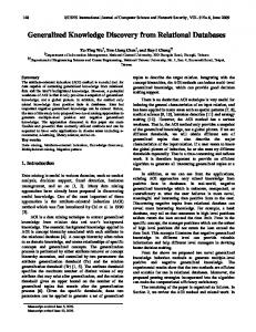
The primary focus of this research is to utilise graph-based formalism to investigate evolution-centric knowledge that
a) Architectural Change
exists in the change log as presented in Figure 1. In this section, we elaborate on the anatomy of change log data and its formalisation using attributed typed graphs [10], illustrated in Figure 1a). This allows us to discover implicit knowledge from logs in terms of analysing change representation and identifying change patterns that can be shared and reused by querying the pattern catalogue in Figure 1b). Architecture Change Log
op1
BillerCRM sendBill () out
Attributes
Attributes
Attributes
Opr
Opr m
Opr
n
Opr
leaf
root
getBill() op3
op1:= ADD(custPayment:CMP, Payment :CFG) op2:= ADD(custBill ("in") :POR,custPayment:CMP) op3:= ADD(getBill: OPT,custBill: PORT) op4:= ADD(billAmount:CON, Payment :CFG) op5:= ADD(billPay:EPT,billAmount: CON) {src = "biller.sendBill ",trg= "custBill.getBill "}
-uID:=aakash_ADM1 -cDate:= 2012-02-17 -cTime:= 13:02:27 -sysID: =EBPP
b) Change Instances in Log
Opr
n
Opr
AE
AE
in
Attributes
m
m
billAmount
custPayment
m
Opr
Opr
m
AE
op2
op4
Architecture Change Graph root
op5
leaf
m
AE
Figure 2: Capturing Change Instances in the Log. Capturing Change Instances
hasConstraints
1..*
Operation
ChangeOperationalisation
Composite
Atomic
Composite
appliedTo
Log Data Classification Change Data
Operational Dependencies hasorder
1..*
Auxiliary Data
Commutative
Dependent
has
Architecture Change Graph
Change Patterns Discovery Exact
Attributes
Attributes
InExact
Opr
m
Opr
Opr root
n
m
leaf
as AD =< uID, cDate, cT ime, sId > captured automatically that consists of user id (aakash−ADM 1), date, time (2012−02−17 13 : 02 : 27 U T C) and the system identifier (EBP P ) to which the change is performed. This is particularly useful for architectural change analysis based on the source, intent, time of change and facilitates in extracting specific (time/user-based etc.) change sessions from log.
Opr
m
AE
AE
a) Change InstanceFormalisation
Pattern Catalogue b) Discovery of Evolution-centric Knowledge
Figure 1: Knowledge Discovery from Change Logs.
2.1 The Anatomy of Change Log Data An architecture change log [7, 18] is a recorded collection of changes (addition, removal or modification) applied to architecture elements. An architecture change log (ACL) captures a sequential list of individual architecture change (AC) instances ACL =< AC1 , AC2 , . . . , ACN >. - Evolution Knowledge Source - In a collaborative environment for architectural development, a change log is a transparent and centrally manageable repository to maintain history of sequential change [7]. It represents a source of evolution knowledge to facilitate with ‘post-mortem’ analysis for architectural change instances. - Architecture Composition - The SOA principles [14] support composition or association type dependencies in service composites. Our architecture meta-model is consistent with the Service Component Architecture that include typed instances of configurations (CFG) among a set of service components (CMP) linked through connectors (CON). Components contain ports (POR) to expose operations (OPT), while connectors provide binding (BIN) among component endpoints (EPT).
- Change Data (CD): contains the core information about individual change instances in the log. This is expressed as CD =< cID, cDesc, OP R, AE[paramList] > representing change id, change description, change operation and the affected architecture elements with its parameter. In the previous example, op1 represents addition of a new component custPayment inside Payment configuration. The source of sample log data are architectural changes for an Electronic Bill Presentment and Payment (EBPP) system and an online Tour Reservation System (TRS). We use the EBPP case study here that involves architectural evolution of an electronic payment system. During change operationalisation for EBPP and TRS individual change instances are automatically recorded in the log that currently comprises of a couple of thousands of changes (AC > 2000). The granularity of change representation ensures completeness of syntax and semantics for recorded changes.
2.2
Graph-based Modeling of Changes
We formalise change instances in the log as an attributed graph (AG) with nodes and edges typed over an attributed typed graph (ATG) [10] with an attributed graph morphism t : AG → AT G as illustrated in Figure 3. The ATG provides formal semantics to allow efficient searching and formal analysis of log data. Regarding the granularity of architectural changes a unified representation for architectural evolution views is lacking [13] that satisfies all stakeholder perspectives. A software developer might be more interested in analysing the modification of a specific operation signature, while an architect would be exclusively concerned with affected component-level interconnections.
An example of architectural change is a sequence of operations that enable addition of a new component custPayment along with its port custBill and corresponding operation getBill (op1, op2, op3). The newly added component custPayment is connected to BillerCRM with addition of a connector billAmount. It provides endpoint binding (op4, op5) among the operations of BillerCRM and custPayment inside Payment configuration. Once sequential architectural changes are captured, change log data is classified as Auxiliary Data (AD) and Change Data (CD) in Figure 2b).
- Analysing operationalisation and dependencies, graph lifting is not utilised in order to study change representation and impact propagation across architecture hierarchy.
- Auxiliary Data (AD): provides the additional details about individual change instances in the log. This is expressed
Creating Change Session Graph: In order to customise change view, we provide a utility method as ses-
- During pattern identification graph lifting [13] is particularly beneficial as it abstracts low-level changes (affecting port, operations, endpoints, binding) into the evolution of configuration, components and connectors in architecture.
on intent, scope or time of architectural changes. In this section, we apply graph matching techniques on change session graph to analyse operationalisation and dependencies for change instances. By abstracting individual change instances into sequential operational compositions we apply sub-graph mining [8] to identify recurring operationalisation that represent patterns of architectural changes as captured in change logs over time. Although a recent emergence of evolution styles [11, 12] promotes architecture evolution reuse, it falls short of addressing frequent demand-driven process-centric changes [16] that are central to maintenance and evolution of SOAs. This motivates the needs to systematically investigate architecture change representation that goes beyond frequent addition or removal of individual components and connectors to operationalise recurrent process-based architecture changes [1] (detailed in Section 4).
sionGraph(uID, strTime, endTime) to automatically create the change graph based on a particular change session in the log. The change session is determined by the identification of the user (uID) who applied changes in a specific time interval (endTime - strTime). For experimental purposes, we consider all the changes in the log as a single session to extract the attributes of change instances that, we generate the lifted change graph (Figure 3a - dotted square) with a concrete represention using the Graph Modeling Language (.GML) format. The result is a directed graph representing sequential composition of change operationalisation, illustrated in Figure 3b. For simplicity, some additional attributes (like date, time, committer of change etc.) from the actual graph are hidden to focus on the sequencing of operations on architecture elements. The attributed graph morphism t : AG → AT G is defined over graph nodes with t(MetaData) = ChangeData that results in t(ChangeOperation) = ADD(), t(ArchitectureElement) = custPayment, billAmount, BillerCRM, t(hasType) = CMP, CON in Figure 3 (constructed with example in Figure 2). We summarise the graph-based formalisation of architectural change instances as:
3.1
Change Operation Classification
Operational classification is vital to enable a fine-granular change representation that goes beyond the fundamental change types [7] to provide the necessary syntax, semantics and composition to operationalise architecture evolution. In the change log, an overlay of architectural changes results in a) atomic changes that can be sequentially combined to enable b) composite changes. Operational classification allows i) quantitative assessment to determine the exact number of change operations required, the cascaded change effects on dependent elements along with ii) qualitative assessment in terms of change consistency and structural validity of architectural hierarchy during evolution.
- Graph Nodes NG = {n(gi )|i = 1, ..., k} represent a set of change operation as t(NG ) = OP R . - Attributed Nodes NA = {n(ai )|i = 1, ..., l} is the set of attribute nodes that are of two types: i) attribute nodes with auxiliary data, and ii) attribute nodes representing architecture elements, where t(NA ) = (AE : hasType). - Graph Edges EG = {e(gi )|i = 1, ..., k − 1} connect source n(g)src and target n(g)trg nodes as the sequencing of change operations, where t(EG ) = eID(NGisrc , NGitrg ).
3.1.1
Atomic Change
It represents the most fundamental unit of architecture evolution in terms of a single change operation applied to an individual architecture element represented as an individual graph node. It builds-up the hierarchical composition of architecture change operations and allows quantitative assessment in terms of total change operations required to execute a specific change. The operational syntax is presented in Table 1, where OP R represents a given change operation applied on the given architecture element (parameter for change operation) and its cascaded impact on other elements in architectural hierarchy. In Table 1, cID repre-
For example in the context of Figure 3b (graph lifting [13] for Figure 2), it is safe to ignore the port and operation level details to argue that the component custPayment used billAmount for inter-connection to BillerCRM inside Payment configuration. The graph nodes are linked to each other using graph edges e(g) as applied sequence of operations.
3. ANALYSING CHANGE INSTANCES The change session graph enables extraction of a (userspecifed) subset of all the change instances in the log based Lifted ATG
oprT ype
ADD REM
oprName ID
Integer nID
totalParam
1456
oprName totalParam
oprName
totalParam
eID
order
Integer
ADD() 1
(typedOver)
AG
CFG
POR
CON
parameterList
String
order
billAmount
(BillerCRM, custPayment )
hasType
hasType
hasType
CON
2
hasParameter
custPayment
CMP
b) AG for Change Operations typed over ATG
EPT
Integer
BIN
totalEndPoints
returnType OPT
1
hasParameter
CMP CMP
order
hasParameter
t ATG
hasType
totalOperations
2
nID
ADD()
Architecture Element
Integer
Add Connector
1 e1
Change Operation order hasParameter
MOD
Add Component
1455
String
endpointBinding
Graph Node
Graph Edge
Attribute Node Attribute Node
Node Attribute Edge
Edge Attribute Edge
a) ATG for Change Operation Syntax
Figure 3: Attributed Graph to Formalise Architecture Change Operationalisation.
sents addition a new operation (OPT) getBill to an existing port (POR) custBill as: ADD(getBill : OPT, custBill : POR). We identified a total of eight atomic changes summarised as: OP Ratomic := {(Add, Rem) }. The generic specification is (OP R) < ArchitectureElement > that enables addition and removal of component operation, component port, connector binding and connector endpoints. cID 27 28 29
OPR Add() Add() Add()
Parameter custPay ∈ CMP custBill∈ POR getBill ∈ OPT
Cascading Change Payment ∈ CFG custPay ∈ CMP custBill∈ POR
Table 1: Operationalising Change Instances
3.1.2
Composite Change
In order to abstract individual change instances into a sequence of atomic changes, we query the graph based on the type of change operation and the co-relation among its parameters. For example, we are specifically interested in sequences of change containing only Add operation such that its parameter elements are co-related in architectural hierarchy. A partial result of the query is represented as the extracted sequence in Table 1. The sequence cID represents the addition of a new component custPayment inside the configuration Payment. The addition of a component is followed by the addition of corresponding port custBill and its operation getBill. The syntactical representation for composite change is identical as presented with the atomic change; however it combines hierarchy of atomic changes in a sequential fashion to enable composite architectural change. This suggests that an exact operational complexity of adding i components that have j ports each containing k operations in architectural composition is expressed as OP R(i∗Composition+j ∗Composite+k ∗Leaf ). It highlights cascading impact of change operationalisation that is propagated from top to the bottom of architectural composition. We identified a total of six composite type changes OP Rcomposite := {(Add, Rem) }. The composite change is essentially a composition of atomic changes that enable the addition and removal of components, connectors and configurations during evolution and allows sequential abstraction of individual change instances.
3.2 Operational Dependencies Abstracting an individual change into a sequence of changes (adjacent graph nodes) allow us to discover operational dependencies. These dependencies are vital in analysing the extent to which architectural change operations are dependent or independent of each other. It is practically beneficial to classify different types of dependencies that allows an architect to select an appropriate change operationalisation based on a given evolution scenario. In addition, operational dependencies allow discovery of ordered and in-ordered recurring change sequences as potential change patterns.
3.2.1
Commutative Change
Composite changes by means of change graph lifting [13] allow traversal of adjacent graph nodes to analyse sequences of change operations based on user-specified minimum and maximum sequence length. Sequence length defines the number of change operations contained in a given sequence. We
utilise structural graph matching among attributed nodes that highlight variations in the order of operations among different sequences although the impact of change remains exactly identical. Continuing with change instance example in Figure 3 two components BillerCRM and custPayment and corresponding connector billAmmount represents (composite changes as) adjacent graph nodes n1, n2, n3 ordering of change operations can be represented as set OP Radd : {(n1; n2; n3), (n3; n2; n1), . . . , (n2; n1; n3)}. Such variations in operational ordering complicate the selection of a given sequence that executes a specific pre-defined change. In addition, it hampers any efforts in discovering sequential change patterns as bijective matching among the ordered operations does not reflect true frequency of patterns that may exist in the log. Therefore, we utilise the concept of operational commutativity to determine if there exists a causal relation between consecutive change operations and the resultant impact of change. Commutative change operations allow sequential composition of changes such that ordering of change operations is insignificant. Sequential composition is of particular interest for the following two reasons: - Operational Extension: allows extension of the fundamental changes Add() and Rem() to define new (modification related) operations. The Modification M od() operations include Move M ov(), Rename Ren(), Split Spl(), Merge M rg() and Swap Swp() operations. For example, moving an existing operation getBill from its current port custBill to a new port custPayment is a sequential composition (;) as addition and removal of component operation: Rem( ); Add( ) - Analysing Sequential Abstractions: allow insight into recurring sequences of composite change that represents potential change patterns. Graph-based formalisation of architectural changes allow us to exploit frequent sub-graph mining to discover sequential change patterns. Sequential change and it sub-types (exact and in-exact) with ordered dependencies are elaborated in Section 4.
3.2.2
Dependent Change
If change operations are not commutative, we regard them as dependent, i.e., the effect of the later change depends on its preceding change operation. Operational dependency is vital to preserve the compositional hierarchy of architecture elements. For Example, in Table 1 the change operations cID represent instances of dependent change. More specifically, the addition of a component (27) must follow addition of the corresponding port (28) and its operation (29). However, only syntactical representation is not sufficient as change semantics must be enforced to preserve the compositional hierarchy. For example, in Table 2 we extend the pure syntactical aspects from Table 1 to providing necessary syntax and semantics for hierarchical composition of change operations. This ensures the compositional hierarchy of architecture elements is preserved and allows qualitative change analysis in terms of consistency of change execution and validity of architectural structure during evolution.
4.
CHANGE PATTERNS IDENTIFICATION
A systematic classification for change operationalisation and dependencies allow us to exploit sequential compositions
Operationalisation ArchitectureElements Constraints Add(custPaymenT, Payment, [CNS]) custPayment ∈ CMP, Payment ∈ CFG
PRE, INV, POST ∈ [CNS]
−Ef f ects on Architecture : adds a new component custPayment into existing configuration Payment. −Operational Constraints : include a set of preconditions (PRE), invariants (INV) and postconditions (POST) as: −P RE : ∄custP ayment ∈ P ayment. The component custPayment do not already exist in Payment configuration. −IN V : ∀CM P ∈ CF G∃hasP OR.OP T . Every instance of component must contains a port and operation. −P OST : ∃custP ayment ∈ P ayment. custPayment is added into Payment and preserving the compositional hierarchy. Table 2: Syntax and Semantics for Hierarchical Composition of Change Operationalisation to identify architecture change patterns. We utilise one of the classical approaches for graph-based pattern mining with sub-graph isomorphism [8] that exists among recurring subgraphs GP to the change session graph GC , where GP ⊆ GC .
Sequence Type Exact Inexact Partial Exact Partial Inexact
TypeEqu true true true true
LenEqu 0 0 ±n ±n
OrdEqu true false true false
4.1 Properties and Types of Change Sequences As detailed in Section 3, the ordering of change operationalisation is insignificant in sequential composition as long as the impact and scope of change remains same. More specifically, during pattern identification we need to analyse the equivalence or distinction among change sequence type, length and operational ordering. In a graph matching context, change sequence properties in Table 3 are vital to not only identify exact instances, but also inexact matches and possible variants of a change pattern where only partial features suffice for pattern identification. We briefly discuss about the type of change sequences and their properties. Type Equivalence (TypeEqu) refers to the equivalence of two change operations in a sequence given by utility function T ypeEqu(OP R1 (aei : AE), OP R2 (aej : AE)) : returns < boolean >. It depends on the type of change operation and the architecture element for a change operation to categorised as type equivalent (return true) or type distinct (returns false). Length Equivalence (LenEqu) refers to the equivalence of length of two change sequences where length of a change sequence is defined by the number of change operation contained in it. It is given by function LenEqu(Sx , Sy ) : returns < integer >. Therefore, the length equivalence of two change sequences Sx and Sy is determined by the numerical value (0 imples Sx == Sy , -n implies Sx < Sy by n nodes and +n implies Sx > Sy by n nodes). Order Equivalence (OrdEqu) refers to the equivalence in the order of change operations of two sequences. Analysing the change log based on a given change session, we observed that it is normal for same user to perform similar changes using different sequencing of change operations. The semantics and impact of change operation remains the same even if sequencing of change operations is varied (i.e., commutative change). It is given by the function OrdEqu(Sx , Sy ) : returns < boolean >. We discovered four different types of change sequences, presented in Table 3. - Exact Sequence: Two given sequences are exact subsequences if they match on operational types, length equivalence and the ordering of the change operations. - Inexact Sequence: Two given sequences are inexact matching sequences if their operational types and lengths are equivalent, but order of change operation varies. - Partial Exact Sequence: Two given sequences Sx and Sy are partially exact such that (if n > 0 than Sy ⊂ Sx , or
Table 3: The Types of Sequences in the Change Log. if n < 0 than Sx ⊂ Sy ) - however, the types and ordering of the change operations in the matched sequences must be equivalent. - Partial Inexact Sequence: Two given sequences Sx and Sy are partial and inexact if (if n > 0 than Sy ⊂ Sx , or if n < 0 than Sx ⊂ Sy ); in addition, the operations within both sequences must be type equivalent, while the order of change operations in both sequences varies.
4.2
Pattern Identification Process
Based on change sequence properties, our solution enables automation along with appropriate user intervention and customisation through parameterisation for change pattern identification. Additional details about graph-based pattern identification are provided in [1]. We follow an apriori-based approach that proceeds in a generate-and-test manner using a Breadth First Search strategy during each iteration to i) generate and ii) validate pattern candidates from change session graph GC and finally, (iii) determine the occurrence frequency of candidate sequences SC in GC . Step 1 - CandidateGeneration(). The initial step of pattern identification generates a set of candidate sequences SC from change graph GC . A candidate consists of a number of nodes representing change operationalisation on architecture elements as a potential pattern depending on its occurrence frequency F req(SC ) in GC . Input(s) is the change graph GC and user specified minimum minLen(SC ) and maximum maxLen(SC ) candidate sequence lengths. Output(s) is a list of generated candidates List(SC ) such that minLen(SC ) ≤ Len(SCi ) ≤ maxLen(SC ). Step 2 - CandidateValidation(). We observed that during candidate generation, there may exist some false positives in terms of candidates that violate the structural integrity (i.e., hierarchical composition) of architecture elements when identified and applied as patterns. Therefore, it is vital to eliminate such candidates through validation for each generated candidate sequence sc against architectural invariants before pattern matching as: - Configuration must contain two components and a connector instances: ∀cf gi ∈ CF G ∃coni (cmpi , cmpj ). - Connector must contain source and target endPoints in-
stances: ∀coni ∈ CON ∃srcpor ∧ trgpor ∈ EP T . - Component must be composed of one or more instances of ports: ∀cmpi,j ∈ CM P ∃por ∈ P OR. Input(s) is a candidate sc ∈ GC (called from candidateGeneration(), each time a candidate is generated). Output(s) a boolean value indicating either valid (true) or invalid (false) candidate sc. Step 3 - PatternMatching(). The last step identifies exact and inexact instances (Table 3) of change patterns based on a user specified frequency threshold. We utilise structural matching with sub-graph morphism [8] among the list of validated candidates vList(SC ) to corresponding nodes in GC . Input(s) is a list of (validated) candidates vList(SC ), specified frequency threshold F req(SC ) and GC . Output(s) is a list of identified patterns consisting of pattern instance GP and its frequency F req(GP ). The candidate is an identified pattern (exact or inexact instance) based on specified frequency threshold: f req(GP ) ≥ F req(CP ) ∈ GP .
5. CHANGE PATTERN CATALOGUE Analysing sequential composition (Section 4) allows us to define change pattern as a generic, first class abstraction (that can be operationalised and parameterised) to support potential reuse in architectural change execution. A change pattern as a generic solution could be i) identified as recurrent, ii) specified once and iii) instantiated multiple times to support reuse in evolution. In order to facilitate sharing and possible reuse of identified pattern instances, we follow on the concept of “evolution shelf” [12], that provides storage and search space to more accurately locate potential process matches in a given evolution context. Therefore, we maintain pattern catalogue as a repository infrastructure enabling a continuous incremental acquisition of identified recurring operationalisations. In addition a query-based retrieval facilitates in utilising the existing patterns to guide architecture evolution. From a functional perspective, we primarily focus on two different aspects: - Knowledge Sharing: In this context, change pattern catalogue is characterised as an updated collection of identified pattern instances that enables sharing and reusing (the problem-solution view as) constrained composition of change operationalisation for common evolution tasks. - Operational Support: From an operational and management perspective, pattern catalogue is a sequential nested graph. Each node represents an individual pattern with its composites (operations, constraints and architecture elements). Each edge establishes a directed link among two adjacent patterns in the catalogue, illustrated in Figure 4. We focus on supporting a flexible specification, classification and retrieval to utilise the existing pattern instances as reusable asset [11] during evolution.
5.1 Pattern Specification We model pattern-based change specification as 5-tuple P atEvol =< CAT, P AT, OP R, CN S, SArch >. In addition to a syntactical specification, the hierarchical relationship among the pattern elements in a catalogue is presented in Figure 4a. Pattern specification is a semi-automated process that facilitates the user with classification and storage of pattern hierarchy inside catalogue structure. In order to
specify patterns, we utilise a graph-database Neo4j1 where a Graph (Catalogue) models Nodes (P atterns) and Relationships (P atternLink). Both nodes and relationships have Properties (Attributes) while edges provide a semantic relationship among nodes and properties, in Figure 4b. CatalogueFramework hasClassification ComposedOf 1..*
Operators
1..*
ChangePattern
Catalogue
ConstrainedBy 1..*
Relationships
Patterns
AppliedTo 1..1
Constraints
organise
ArchitectureModel 1..* Constrains
a) Meta-model for Change Pattern Specification
Properties
b) Graph-based Pattern Storage
Figure 4: Pattern Specification in the Catalogue.
- Structural Perspective: For each pattern instance (P AT ), change operationalisation (OP R), constraints (CN S) and the affected architecture elements (SArch) are visualised. This allows user to view the overall impact of change on existing sub-architecture before (preconditions) and after (postconditions of) change operationalisation with an appropriate name and intent of specified pattern. - Semantical Perspective: A pre-defined Pattern Classification types CLS =< Inclusion, Exclusion, Replacement > provides a representation of individual patterns based on their impact (integration, decomposition, replacement type changes etc.) on architectural elements. It allows change categorisation among patterns for efficient retrieval and is a fundamental step towards building semantic relationships among patterns that exist in the catalogue (additional details are out of the scope for this paper). An individual instance is specified as P AT
:
P OST (ae′m
P RE(aem ∈ AE) −−−−−−−−−−−−−−−→ ∈ AE). Explicit constraints on operationalisation ensures structural integrity of architecture during pattern-based evolution.
5.2
Pattern Retrieval
Reusing specified pattern instances requires a query-based mechanism to retrieve appropriate pattern instances in a given evolution context. From an operational perspective, an inherent benefit while utilising Neo4j lies with exploiting Cypher - a declarative graph query language - that allows expressive and efficient querying of the catalogue to retrieve part or the whole pattern structure. For the evolution scenarios from the EBPP case, this requires the integration of a newly added components billType into the existing architecture, as illustrated in Figure 6. The intent of change is to allow customers a billing type option (monthly or weekly) for their payment in addition to the existing advance billing option. We follow a three step approach that enables the user to specify change intent and constraints that supports querying the catalogue to retrieve the appropriate pattern instance, see Table 4. i) Change Intent: allows a declarative specification for syntactical context of architectural change that contains the architecture elements (AE) that need to be added, removed or modified in the existing architectural structure SArch 1
Neo4j Graph Database: http://www.neo4j.org
Integr(SArch, [CN S], < billT ype, BillerApp, custBill >) PRE (preConditions) ∃(BillerApp, custBill ∈ CM P ) ⊆ SArch ∃billingData(BillerApp, custBill) ∈ CON ⊆ SArch POST (postConditions) ∃(BillerApp, custBill, billT ype ∈ CM P ) ⊆ SArch ∃billT ypeData(BillerApp, billT ype) ∈ CON ⊆ SArch ∃getT ype(billT ype, custBill) ∈ CON ⊆ SArch < PAT > retrievePattern(PRE, POST) ∀pati ∈ P AT ∃pati .P RE ∧ pati .DEF ∧ pati .P OST (pati .P RE ≡ P RE ∧ pati .P OST ≡ P OST ) ∈ CAT return(pati .DEF )
b)ChangeOperationalisation 2 3
billType
Component
4
in
out
getType
billiTypeData
Ports
billingData
custBill
BillerApp
connector
1
billType billingData
BillerApp generateInvoice
consInvoice
billiTypeData
custBill adjustAccount
accMgmt
a) Preconditions
getType
BillerApp
custBill
generateInvoice
adjustAccount
consInvoice
accMgmt
c)Postconditions
Figure 5: Instance of Linear Inclusion Pattern. Table 4: Specifying Change Intent and Constraints such that AE ∈ SArch. Contrary to obtaining information about all the patterns that exist in the catalogue, this approach facilitates a user to focus on problem definition (intended change and structural constraints) view, while catalogue provides a list of appropriate change patterns. For example, in the context of existing architecture user intends integration of a new component billType among the existing BillerApp and CustBill components in SArch. ii) Constraints Enforcement: consists of specifying the preconditions (PRE) and postconditions (POST) that must be satisfied to preserve the structural integrity of the overall architecture and individual elements during change execution. In addition, the constraints allow a matching criteria in the pattern hierarchy inside catalogue to retrieve an appropriate list in a given evolution context. The precondition(s) represent the context of architectural structure before change execution. The postcondition(s) specify the context of evolved architectural elements as a consequence of the change execution. For example, change preconditions in Table 4 specifies that BillApp and custBill components are connected using the billingData connector. The postconditions ensure that newly added component billType is integrated among the existing components BillerApp and custBill, while removing the connector billingData. iii) Pattern Retrieval: once the intent and constraints of architectural change are specified, the catalogue is queried with change pre-conditions and post-conditions to retrieve the appropriate pattern instances that exist in the catalogue (concrete syntax as Cypher query language omitted here). Figure 5 illustrates the retrieved instance of Linear Inclusion pattern that aims at ‘integration of a mediator among two or more directly connected service components’. In addition, pattern instantiation involves labeling of generic elements in specification with labels of concrete architecture elements presented in change specification. For example, in Figure 5a (partial architectural view) the connector instance billingData missing in the change post-conditions is removed. The newly added instance(s) of component billType and connector billTypeData, getType are the candidates for addition into SArch to obtain evolved architecture in Figure 5c
5.3 Experimental Analysis and Evaluation Change operationalisation and pattern identification from potentially large change logs requires an efficient solution. Experimental analysis and illustration of identified pattern instances are presented in our previous work [1]. - Algorithmic Complexity: In our trials, we observed that
preprocessing for a significant graph size (i.e, GC .size() = AC ≥ 2278) remains constant with average complexity time = 888.9 ms. We customise the input parameters as: minLen(SC ) = 2, maxLen(SC ) = 9 with total change operations: GC .size() = 2278. In addition, we increase the pattern frequency threshold F req(SC ) by 2 in each trial, where T ime ∝ F req(SC ) and F req(SC ) ∝ 1/Instances. The difference between the exact and inexact pattern sequences is detailed in Section 4. The summary of comparison (on average): time (exact : inexact) in milliseconds = T(564:1214) ms and identified patterns instances (exact : inexact) = I(21:38), for GC .size() = 2278. - Tool Support: In order to model change instances as an attributed graph, we utilise the .GML (Graph Modeling Language) format. After pattern identification, we provide the Pat-Lib repository for change pattern specification using Neo4j graph database. This allows us a continuation in the development of Pat-Evol (Pattern Evolution Framework) as an integrated tool-chain to empower an architect in modeling and executing reusable evolution. Change instances in the log correspond to the architectural meta-model, i.e. composition only supports association or composition type (structural) dependencies among service composites. Applying this knowledge in a more general evolution perspective is not guaranteed. For conventional object-oriented systems, type inheritance and aggregation type dependencies and their impact could not be analysed with proposed solution. An interesting identification is the emergence of change anti-patterns resulting from counterproductive pattern-based evolution. This leads us to believe that change patterns do not necessarily support an optimal solution; instead they promote an alternative and potentially reusable operationalisation for evolution. Experimental identification of potential anti-patterns and their resolution is vital for reliable architecture evolution.
6.
RELATED WORK
We follow on the taxonomy of software evolution [7] with graph-based formalisation of architectural change instances in the log to discover recurring operationalisation and patterns that can be shared and reused to guide architectecturecentric evolution. The authors in [18] focus on analysing architecture revision history to perform fine grained analysis to detect the evolutionary coupling between architecture elements. In contrast, we utilise architecture change logs to perform the ‘post-mortem’ analysis in analysing architecture
change representation that aggregates over time. This provides us with an empirical foundation to abstract sequential operational composition to identify architecture change patterns. The pattern identification process is guided by [15] that propose a (modular) algorithmic solution for mining sequential patterns from a database of customer sales transactions. Graph-based formalisation facilitates in leveraging the frequent sub-graph mining approaches [8] to discover recurrent operationalisation as potential change patterns. Although solutions like the “evolution shelf” [12] provide a generic infrastructure to achieve for-reuse and by-reuse techniques for software architecture evolution. It aims at supporting refactoring patterns (i.e., add a component, move a component etc.) that can be composed into further advanced evolution styles (add a client, move a client etc.). In contrast to the evolution styles [12, 11] for more conventional component architectures, we observe that operationalisation of changes in the log exhibits process-centric patterns of change unlike the frequent addition or removal of individual components and connectors. It is vital to mention about a catalog of process change patterns [16] that guides changes in process-aware information systems. In contrast to the process aspects of software, we exclusively focus on change operationalisation at architectural abstraction levels accommodating patterns to guide structural evolution. While mining process-based changes abstracting sequential composition is particularly significant to go beyond the more conventional primitive architectural changes to operationalise frequent process based changes that are central to maintenance and evolution of service architectures.
7. CONCLUSIONS AND OUTLOOK The primary focus of the proposed research was an empirical investigation into the history of sequential changes to analyse the operational aspects of architecture evolution. This enables exploiting sequential change patterns to support reuse for process-based changes at an architectural level of abstraction. In a knowledge sharing context, a pattern catalogue provides an updated collection of identified pattern instances to enable sharing and reusing a constrained composition of change operations for common evolution tasks. Future work is concerned with guiding architectectural transformation by means of instantiating change patterns. In [2], we argue that the notion of ‘build-once, use-often’ philosophy could enhance the role of an architect to model and execute generic and potentially reusable solutions to recurring architecture evolution problems. Currently, we are working on the development of a graph-transformation system to support architecture evolution guided by change patterns. The tool and the generated data shall form the basis for practitioners (software architects) for a survey and usability based analysis to evaluate the adequacy and applicability of the proposed solution in a practical context.
8. REFERENCES
[1] A. Ahmad, P. Jamshidi, and C. Pahl. Graph-based Pattern Identification from Architecture Change Logs. In International Workshop on System/Software Architectures, 2012. [2] A. Ahmad, P. Jamshidi, and C. Pahl. Pattern-driven Reuse in Architecture-centric Evolution for Service Software. In 7th International Conference on Software Paradigm Trends (ICSOFT), 2012.
[3] M. Javed, Y.M. Abgaz, C. Pahl. A pattern-based framework of change operators for ontology evolution. In: On the Move to Meaningful Internet Systems: OTM Workshops, LNCS, vol. 5872. 2009. [4] V. Gruhn, C. Pahl, and M. Wever. Data Model Evolution as Basis of Business Process Management. In 14th International Conference on Object-Oriented and Entity Relationship Modelling O-O ER’95. Springer-Verlag (LNCS Series), 1995. [5] V. Gacitua-Decar and C. Pahl. Pattern-based Business-Driven Analysis and Design of Service Architectures. 3rd International Conference on Software and Data Technologies ICSOFT’2008. 2008. [6] H. P. Breivold, I. Crnkovic, and M. Larsson. A Systematic Review of Software Architecture Evolution Research. Information and Software Technology, 54(1):16–40, 2012. [7] J. Buckley, T. Mens, M. Zenger, A. Rashid, and G. Kniesel. Towards a Taxonomy of Software Change. Journal of Software Maintenance and Evolution, 17:309–332, 2005. [8] C. Jiang and F. Coenen and M. Zito. A Survey of Frequent Subgraph Mining Algorithms. 2004. [9] C. Pahl. A Formal Composition and Interaction Model for a Web Component Platform. In ICALP’2002 Workshop on Formal Methods and Component Interaction. ENTCS. 2002. [10] H. Ehrig, U. Prange, and G. Taentzer. Fundamental Theory for Typed Attributed Graph Transformation. In Graph Transformations, pages 161–177. 2004. [11] D. Garlan, J. Barnes, B. Schmerl, and O. Celiku. Evolution Styles: Foundations and Tool Support for Software Architecture Evolution. In Proc. Working IEEE/IFIP Conf on Software Architecture, 2009. [12] O. L. Goaer, D. Tamzalit, M. Oussalah, and A. D. Seriai. Evolution Styles to the Rescue of Architectural Evolution Knowledge. In Intl Workshop on Sharing and Reusing Architectural Knowledge, 2008. [13] H. Fahmy and R.C. Holt. Using Graph Rewriting to Specify Software Architectural Transformations. In Intl Conf on Automated Software Engineering, 2000. [14] G. Lewis and D. Smith. Service-Oriented Architecture and its Implications for Software Maintenance and Evolution. In Frontiers of Software Maintenance, 2008. [15] R. Agrawal and R. Srikant. Mining Sequential Patterns. In 11th Intl. Conference on Data Engineering, 1995. [16] B. Weber, S. Rinderle, and M. Reichert. Change Patterns and Change Support Features in Process-Aware Information Systems. In Intl. Conf. on Advanced Information Systems Engineering, 2007. [17] R. Barrett, L. M. Patcas, J. Murphy, and C. Pahl. Model Driven Distribution Pattern Design for Dynamic Web Service Compositions. In Intl Conf on Web Engineering ICWE’06. ACM. 2006. [18] T. Zimmermann, S. Diehl, and A. Zeller. How History Justifies System Architecture (or not). In Intl Workshop on Principles of Software Evolution, 2003.