Proceedings of the 39th Hawaii International Conference on System Sciences - 2006
Graph Transformations for Dynamic Knowledge Processing Bodo Kraft
Daniel Retkowitz
Aachen University of Technology Department of Computer Science III Ahornstr. 55, 52074 Aachen, Germany Email:
[email protected]
Aachen University of Technology Department of Computer Science III Ahornstr. 55, 52074 Aachen, Germany Email:
[email protected]
Abstract— The conceptual design phase at the beginning of the building construction process is not adequately supported by any CAD-tool. Conceptual design support needs regarding two aspects: first, the architect must be able to develop conceptual sketches that provide abstraction from constructive details. Second, conceptually relevant knowledge should be available to check these conceptual sketches. The paper deals with knowledge to formalize for conceptual design. To enable domain experts formalizing knowledge, a graph-based specification is presented that allows the development of a domain ontology and design rules specific for one class of buildings at runtime. The provided tool support illustrates the introduced concepts and demonstrates the consistency analysis between knowledge and conceptual design.
I. I NTRODUCTION The building construction process is subdivided into different phases. The first phase of the construction process is called conceptual design. In this early phase, the architect defines the functionality and organization of the whole building instead of a detailed worked-out construction. The constructive design, based on the conceptual design, is elaborated in later phases. During conceptual design, the architect has to observe numerous legal, economical, and design-technical restrictions. In addition, the functionality of the building, i. e. the correct arrangement of rooms, their equipment, and meaningful relations between them, has to be guaranteed. Currently, architects still use pencil drawings for developing first sketches of the future building. This information, specified in the conceptual design phase, is essential for all following phases. However, current industrial CAD tools are restricted to store only constructive design information, i. e. all semantics, stored in the pencil drawing explicitly or implicitly, gets lost. Thereby, all conceptual information has to be stored in additional documents mostly in an informal way. The correctness of the sketch in terms of regarding all given restrictions has to be observed manually, as no tool support for conceptual design analysis exists. A. ConDes Project The ConDes (Conceptual Design) project aims at elaborating a new conceptual design support for industrial CAD-tools. To provide more adequate tools for the early design phase, we introduce and implement roomobjects and roomlinks [1]
with predefined semantics by way of example to the CADtool ArchiCAD [2] on the one hand. On the other hand we develop graph-based support for the domain of architectural engineering, especially for the formalization of conceptual design knowledge and consistency analyses checking a conceptual design. For knowledge specification, we provide a graph-based visual language [3] used by a knowledge engineer. The knowledge engineer [4] is in our approach a domain expert, i. e. an experienced architect or civil engineer and not a computer scientist. Thus, knowledge formalization has to be done in a visual and easily usable way. To be able to evaluate the formalized knowledge, we further provide a graph-based conceptual design tool used by an architect for developing early conceptual sketches. Restriction violations are automatically discovered and highlighted in the conceptual sketch. The developed concepts are implemented using the graph rewriting system PROGRES [5]; the UPGRADE framework [6] serves as basis for generating userfriendly visual applications. B. Related Work In the field of early architectural design, Christopher Alexander describes a way to define architectural design patterns [7]. Although design patterns are extensively used in computer science, this approach has never been formalized, implemented and used in architectural design. The SEED system [8] provides a support for the early phase in architectural building design. Different modules –SEED-Pro, SEED-Layout and SEED-Config– allow for specifying the requirements of the buildings, generating floor plans and three dimensional models based on these requirements. Knowledge specification is done in so called specification units, storing the requirements of the future building. Even if the SEED approach also provides user interaction, mainly the generation of building sketches is aimed at and not an integrated, interactive design support. Graph rewriting has been used by G¨ottler [9] to build a CAD-tool that supports the design of a kitchen. In contrast to our approach, the domain knowledge is not dynamic, but it is fixed in the specification. In [10][11], graph grammars are used to find reasonable positions of rooms and to generate an initial floor plan as a suggestion for the architect. In [12],
0-7695-2507-5/06/$20.00 (C) 2006 IEEE
1
Proceedings of the 39th Hawaii International Conference on System Sciences - 2006
functional requirements for a building, especially the traffic flow inside, are formalized in UML use case and UML activity diagrams. These diagrams are then mapped onto a room graph representing an abstract structure of the future building. In contrast to our approach, all knowledge is fixed in the PROGRES specification and can only be defined by a computer scientist. Moreover, this approach focuses the formalization of the buildings’ usage. The approach presented in this paper is more general and allows knowledge formalization for different domains. In [13], an informative overview on knowledge representation is given. Five distinct roles are identified and discussed to explain the term knowledge representation independently from an actual knowledge representation. A lifecycle for knowledge –definition, use, adaption, and reuse– is described in [14]. A distinction is made here between internal and external knowledge and the lack of meaningful formalization methods is identified. Finally, the CoMem system, a kind of knowledge browser, is demonstrated without describing the internal realization. [15] engages in an empiric survey. According to this survey, a visual representation of knowledge using e. g. semantic nets [16] is more clearly comprehensible than a textual representation like e. g. predicate logic. The semantic web approach [17] tries to improve the quality of information in the world wide web. This approach forms the basis of RDF [18], a language developed especially for modeling knowledge. In [19], an ontology definition specification is presented that supports expressive knowledge representation for multiple ontologies. The approach is based on the semantics of UML [20]. We use a UML-like representation of formalized domain knowledge as well, but we implement it with specifically tailored graphs and achieve a higher expressiveness. We further provide concepts for knowledge formalization optimized to the addressed architecture and civil engineering domain, and not for arbitrary knowledge. Finally, we develop consistency analyses checking the conceptual design against the defined knowledge by complex graph-transformations. C. Paper Overview In this paper, the graph-based knowledge specification part of the ConDes project is presented. In the next section, we introduce the system architecture to provide an orientation about the parts concerned in this paper and their context in the complete project organization. A parameterized and layered PROGRES specification is presented which allows for creating and processing a host graph, containing a domain ontology, and design rules, both dynamic at tool runtime. Furthermore, the motivation for dynamic knowledge specification is discussed. The following main part of the paper describes a graph-based specification for dynamic knowledge processing based on PROGRES. By way of the dynamic approach, we distinguish different kinds of instantiation mechanisms, the PROGRES node type instantiation and the dynamic instantiation of ontology elements. In the following section, some design rules concerning a conceptual building design are presented by way of an example host graph. Graph-based parameterized design
checks identify conceptual design errors, their functionality is shown by way of example, too. Finally, two screenshots depict the developed tool support that abstracts from the internal graph structure to give a user-friendly representation. In a summary, the expressiveness of the provided knowledge definition language and their complexity is discussed, and an outlook of future extensions is given. II. K NOWLEDGE F ORMALIZATION S YSTEM A RCHITECTURE Knowledge formalization in conceptual architectural design covers rules and restrictions concerning the internal organization of a building, e. g. the equipment and arrangement of rooms, the aggregation of rooms to cohesive areas, or the allowed respectively restricted traffic flow inside a building. The architect has to resolve the difficulty of developing a conceptual sketch of the future building which is consistent to all defined restrictions. Further analyses, e. g. static, stress or climatisation calculations, are elaborated by civil engineers in later phases. These analyses are based on a detailed constructive sketch, with a complete specification of all materials and components. In our work, we concentrate on the support of the conceptual design phase, in this paper especially on the knowledge formalization part. A. Visual Knowledge Formalization We follow a dynamic knowledge formalization approach, i. e. a domain expert, an architect or a civil engineer, should be able to formalize his personal domain knowledge. In a fixed approach, the domain knowledge would be formalized by the tool developer as an internal part of the source code. In our scenario, knowledge formalization is done in two steps: First, the basic concepts, i. e. semantic objects, relations, and attributes, have to be defined in a domain ontology. Based on this conceptualization [21], design rules are used in a second step to insert conceptual relevant knowledge. The ontology as well as the formalized knowledge is specific to one class of buildings, both are valid for any project of the corresponding class. The domain ontology [22] is prestructured in three basic elements: • Semantic objects describe the conceptually relevant functional entities in architectural design, • Relations describe connections between semantic objects, • Attributes describe necessary equipment or properties of a semantic object. Semantic objects are defined by the knowledge engineer at tool runtime for one class of buildings. We support the knowledge engineer in developing the domain ontology by providing predefined fundamental concepts for conceptual architectural design. These concepts, building site, building, storey, area, room, and section have invariant semantics, independent from the class of buildings. They, as well as their aggregation relation, are fixed in the ontology model part of the PROGRES specification (ref. figure 3).
2
Proceedings of the 39th Hawaii International Conference on System Sciences - 2006
Attribute Surface Area
Semantic Object
Relation
Room
Access
Area
Section
Fixed Ontology Model – Predefined Terms
Attribute Rule
Sanitary Room
min = 10 max = 15 Relation Rule
Lounge
Staff Access
Dynamic Domain Ontology Garage Surface Area
Customer Room Customer Room Lounge
Contact
Sanitary Room Exposition
Toilet
Men’s Toilet
Handicapped Toilet
Staff Access
Customer Access
Customer Access
Car Repair
srcMult = 0 trgMult = 0 Cardinality Rule
Handicapped Toilet
Cardinality min = 1 max = 3
Women’s Toilet
Fig. 2. Fig. 1.
Car Repair
srcMult = 1 trgMult = 1..5
Garage Access
Garage Room
Surface Area
Example design rules
Cutout of domain specific ontology
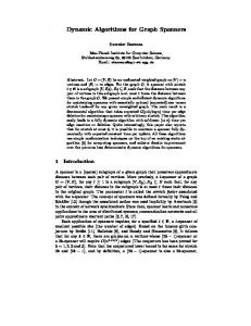
The new defined semantic objects are the fundamental components of the design rules. Their definition requires specialized domain knowledge. The conceptual relevant attributes and relations are defined analogously. Figure 1 depicts a cutout of the (fixed) ontology model and a sample domain ontology, specific for car-garages. The predefined ontology model element room is used to define the semantic object garage room as a root node for the domain ontology. The semantic objects customer room, sanitary room, and their subclasses inherit from garage room. In addition, there is an attribute surface area and a relation access predefined. The relation access is used by the knowledge engineer to define a customer access and staff access. The definition of design rules is based on two parts. One part is runtime dynamic and consists of the elements defined in the domain ontology. The second part, namely the design rule model, is fixed in the PROGRES specification. It consists of predefined types of design rules, e. g. attribute rules, relation rules, and cardinality rules. Attribute rules allow for defining properties for one semantic object, e. g. a size restriction or the demand respectively the prohibition of certain equipment. Relation rules demand or forbid an interrelationship between semantic objects, e. g. the access between two rooms. Cardinality rules restrict the number of occurrences of semantic objects in the building design. Further rule types (aggregation rules, complex path rules, etc.) and advanced concepts (multiplicity restrictions, complex and runtime dynamic expressions, etc.) are available, but not covered in this paper. See [23], [3] for further information. Four examples of basic design rules are depicted in their abstract syntax in figure 2. The attribute rule depicted topmost expresses a restriction of the surface area for sanitary rooms, which has to be between 10.0 and 15.0 sqm (ref. [24]). Looking at the domain ontology (figure 1), one can identify four semantic objects inheriting from sanitary room. Corresponding to this inheritance hierarchy, the attribute rule is automatically valid for all four subclasses as well. Figure 2 further depicts two relation rules. The first relation rule demands a staff access
relation between the customer lounge and the car repair. The number of allowed connections is specialized by multiplicity restrictions of the relation: Each lounge has to be connected by the staff access relation to at least one and at most five car repair rooms. For the second relation rule the multiplicities are specified to be zero. Thus, the rule forbids customer access from any customer room to a car repair room. Finally, the cardinality rule at the bottom of figure 2 demands at least one and at most three handicapped toilets to be installed inside the garage. The abstract syntax [25] depicted in figure 2 serves for illustrating the internal structure of design rules. A more user-friendly concrete syntax is provided by the visual tool, presented in section V. B. System Architecture Graphs as a general data structure allow for storing the needed information for our knowledge formalization approach. The graph rewriting system PROGRES provides the possibility to specify a graph schema for defining a valid class of graphs. Graph transformations are specified to build-up and modify a graph at runtime (host graph). In this way, we develop purely graph-based programs, all functionality is realized by graph tests, graph transformations, and control structures provided by the PROGRES language. All program data is stored in graph nodes and edges. To execute these graph-based programs we use the UPGRADE framework which provides the functionality to represent and layout graphs, and to execute the graph transformations defined in PROGRES. The UPGRADE framework is highly extendable and customizable. In our project we extend it to the needs of knowledge formalization. The complete project scenario consists of two parts, the knowledge formalization part on the one hand and the conceptual design part on the other hand. We combine both parts by checking the conceptual design against the formalized knowledge. These design checks are graph-based as well, they notify the architect if his sketch violates the given restrictions. The knowledge formalization part is structured in a multilayered graph specification. Based on the PROGRES language, the PROGRES specification is structured in four layers that
3
Proceedings of the 39th Hawaii International Conference on System Sciences - 2006
PROGRES Language
Conceptual Design Package Ontology Model Package Design Model Package
PROGRES Specification
Base Package Knowledge Specification Package
Hostgraph
Domain Ontology Specific to one class of buildings
Design Rules static instantiation runtime instantiation
Specific to one class of buildings
Fig. 3. Multi-layered system architecture for dynamic knowledge formalization
stepwise encapsulate realization details and provide higherlevel functionality. The complete specification does not contain any domain knowledge specific to a class of buildings, but it provides the functionality to formalize domain knowledge at tool runtime. The approach is parameterized in two perspectives: first, the domain ontology (see figure 1) is not fixed in the PROGRES graph schema, it is created at runtime by a knowledge engineer. This way the ontology can be designed specific to a certain class of buildings and specific to a certain knowledge sub domain, e. g. fire prevention or other legal restrictions. Second, the actual domain knowledge (see figure 2), can be defined at runtime in terms of design rules. Looking at figure 3, the initial point of the system architecture is the PROGRES language and its provided expressiveness to describe and modify arbitrarily attributed, node- and edgelabeled graphs. At our department, PROGRES is used for several projects from diverse application domains (project management, telecommunication, etc.). The most general package of the specification is called base package, it realizes the fundamental parts. First, the basic types for modeling (semantic object, attribute and relation) and their relationships in the graph are defined in the basic graph schema. Because of the two-phase knowledge formalization approach a runtime instantiation mechanism is needed. This mechanism allows to build-up the domain ontology and to instantiate its elements for defining design rules. To be able to dynamically develop object-oriented structured ontologies, a mechanism to define a runtime-dynamic inheritance hierarchy and runtime-dynamic aggregation relationships are realized in the base package. Finally, some basic operations for maintenance and graph queries of the runtime graph are provided in the base package. Because these features are used for the conceptual design support as well, the base package is independent from knowledge specification. The second layer of our system architecture comprises the knowledge specification package, to fix the specifics of the knowledge formalization approach. Using the defined
functionality of the base package, specialized graph nodes for domain ontology elements and for design rule elements are defined. Furthermore, the different types of design rules (e. g. attribute, relation, and cardinality rules) are fixed here. The knowledge specification package is furthermore fundamental for the design checking package (not depicted) implementing the consistency analyses. Up to here, the PROGRES specification does not contain any domain specific information, it could be used for knowledge specification from several domains. To provide a more adequate support for the domain of conceptual design in civil engineering, we fixed basic architectural knowledge inside the specification, thoroughly modularized in the conceptual design package. Basic concepts (area, room, section, etc.), and fundamental calculations (e. g. surf ace = width ∗ length, volume = surf ace ∗ height, etc.) are predefined here to give the knowledge engineer a reasonable basis for the elaboration of domain knowledge. Additionally, more powerful consistency analyses are possible using the domain specific base knowledge. The bottom layer of the PROGRES specification is subdivided into two parts. The domain ontology model package is for ontology definition, it provides all functionality to define, classify and aggregate semantic objects, and to specify the needed attributes and relations. The second part consists of the design rule model package that contains all functionality to define design rules, based on the domain ontology and on the predefined design rule types. In contrast to the knowledge specification package, which defines the basics for knowledge formalization, the concepts defined in this layer are more abstract and allow a comfortable handling. Corresponding to the bottom layer of the PROGRES specification, the host graph is also sectioned in two main parts. One part is used to store the domain ontology, a second part to store design rules. Both parts are developed at tool runtime and specific to one class of buildings e. g. car garages. Looking at the bottom of figure 3, this separation is represented by two boxes. The ontology elements in the host graph, depicted in the left box, are instances from PROGRES node types defined in the domain ontology model package. This part describes the common, static PROGRES instantiation mechanism, its consistency is ensured by the PROGRES runtime environment. The design rule elements, depicted in the right lower box, are also instances from PROGRES node types, which are defined in the design rule model package. Up to here, these elements are still unspecific placeholders for storing design rule elements in the host graph. The assignment of design rules to the previously defined, domain specific concepts is established by way of associating ontology elements to design rule elements. Because both parts –ontology elements and design rule elements– are runtime dynamic in the host graph, the assignment cannot be realized through the PROGRES runtime environment, but is manually implemented within the PROGRES specification. We call this mechanism runtime dynamic instantiation.
4
Proceedings of the 39th Hawaii International Conference on System Sciences - 2006
ONTOLOGY _OBJECT
isA
0..1
isA
ONTOLOGY 0..n _RELATION 0..n
1
0..n
instance_of
0..1
0..1
ONTOLOGY _SEMANTIC _OBJECT 1
1
ONTOLOGY _ATTRIBUTE
INSTANCE _RELATION
to_rel
INSTANCE _OBJECT
1
from_rel 1 0..1
1 INSTANCE _SEMANTIC _OBJECT
0..1 to_attr
INSTANCE _ATTRIBUTE
0..n 0..n
Fig. 4.
CONTAINS
Base package implementing the dynamic instantiation, inheritance, and aggregation
III. BASICS OF THE PARAMETERIZED S PECIFICATION A PPROACH In this section we describe the basics of our specification, which are fundamental for our approach. The PROGRES graph schema for knowledge formalization consists of several layers as discussed in the previous section. Here, we concentrate on the base package implementing the runtime dynamic instantiation mechanism. The base package is independent from the knowledge specification, in the complete scenario the provided functionality is also used for the conceptual design part of our project. Therefore, the presented concepts are at the level of general graph nodes. A. Runtime Dynamic Instantiation Figure 4 shows two parts in the graph schema. The left hand side of the figure depicts the graph schema nodes here used for the ontology elements, the right hand side of the figure depicts the graph schema nodes for design rule elements. Both parts are connected, via the instantiation relation, because the design rule elements are instances of the ontology elements. In the following, this runtime dynamic instantiation mechanism is explained in more detail. There are two root nodes, ONTOLOGY OBJECT for the elements in the domain ontology, and INSTANCE OBJECT for the design rules. The instance of-edge, connecting the two root nodes, realizes the runtime instantiation relation between ontology elements and design rule elements. Each time a new instance object is created, e. g. a certain semantic object, the instance of-edge is established to the corresponding semantic object in the domain ontology. We call this mechanism, depicted as dashed line in figure 3, runtime dynamic instantiation (see previous section). This instantiation has to be done at runtime, since the domain ontology as well as the design rules are elaborated at tool runtime and stored in the PROGRES host graph. According to the graph schema, the instance relation is not typed, i. e. an attribute could be an instance of a relation and so on, because it would be possible to connect them with an instance of-edge. The type equivalence between ontology elements and instance elements is ensured by means of the PROGRES transformations, for the creation of these instance
elements. When an instance of an ontology element is created, the type of the new node is automatically set correctly according to the instantiated ontology element. The reason not to use different types of instance of-edges in the graph schema is to keep it more concise and to avoid many case differentiations in PROGRES transformations following these edges. So even though the instance relationship is on an abstract level in the graph schema, the type equivalence can be guaranteed through the concerned PROGRES transformations. B. Ontology Part In the ontology part and instance part there is a root node ONTOLOGY OBJECT and INSTANCE OBJECT, respectively. On both sides, the root node is further specialized into the three basic concepts semantic object, relation, and attribute. On the ontology side, there are isA-edges attached to the nodes for semantic objects and relations. These edges are used to implement inheritance in the dynamic domain ontology. An isA-edge connects the node of a specialized concept to the node of a more general one. The multiplicity shows that we do not allow multiple inheritance for simplicity reasons. In contrast to relations and attributes, semantic objects can also be aggregated. Using runtime dynamic aggregation, the knowledge engineer can develop complex semantic objects, composed of other semantic objects. The runtime dynamic aggregation is realized by a reflexive CONTAINS-relation, storing the encapsulated semantic objects, and their multiplicity. One can see that each complex semantic object can consist of arbitrary many semantic objects, analogously each semantic object can be part of arbitrary many aggregations. C. Instance Part On the instance side of the graph schema (right hand side of figure 4), the three basic design rule elements and their connections are implemented. These elements are linked up to describe the three different design rule types (ref. figure 2). An attribute rule consists of one INSTANCE SEMANTIC OBJECT, connected with a to attredge to one INSTANCE ATTRIBUTE; it defines a valid range of values for the attribute. Relation rules consist of two INSTANCE SEMANTIC OBJECTS, interrelated by
5
Proceedings of the 39th Hawaii International Conference on System Sciences - 2006
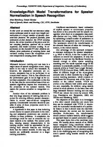
an INSTANCE RELATION and corresponding to rel- and from rel-edges. According to the edge multiplicities, each INSTANCE SEMANTIC OBJECT is related to only one relation. This design decision was made to ease consistency analyses and knowledge modularization. As already mentioned, the graph schema depicted here is part of the base package. The cutout of this graph schema is extended in all following packages to complete the knowledge specification approach. D. Host Graph Example To illustrate the introduced functionality, figure 5 depicts an example host graph. The upper part of the figure shows a cutout of an example domain ontology at tool runtime. Six ONTOLOGY SEMANTIC OBJECTS are defined, structured by inheritance starting from Room. Furthermore, two ONTOLOGY RELATIONS and one ONTOLOGY ATTRIBUTE are shown. The lower part of the host graph shows the runtime representation of some design rules. Their connections to the corresponding nodes in the ontology are established by way of instance of-edges from the graph nodes in the design rules part to those representing the ontology elements. The design rule part depicts four rules: one integer attribute rule (IAttrRule1), two reference rules (RefRule1, RefRule2), and one cardinality rule (CardRule1). A reference rule is automatically derived for specialized semantic objects, according SurfaceArea : KM_IntAttr
Room : KM_SemO
Access : KM_Relation
is A
CustomerRoom : KM_SemO
isA
is A
SanitaryRoom : KM_SemO
isA
isA
Lounge : KM_SemO
Toilet : KM_SemO
StaffAccess : KM_Relation
isA
instance_of
HandicappedToilet : KM_SemO
instance_of
Domain Ontology Design Rules SanitaryRoom : K_SemO to_
to_concerns
IAttrRule1 : K_IAttrRule
att
r
SurfaceArea : K_IAttr
rule_attr
to_min to_max
to_rule
RefRule 1 : K_RefRule
: K_ConstInt value = 10 : K_ConstInt value = 15 instance_of
to_concerns
Toilet : K_SemO
to_concerns
HandicappedToilet : K_SemO
to_rule
RefRule 2 : K_RefRule
instance_of
instance_of
HandicappedToilet : K_SemO to_concerns
CardRule 1 : K_CardRule
to_card
Fig. 5.
: K_Cardinality _Range
Example host graph
to_min to_max
: K_ConstInt value = 1 : K_Star
to the ontology. In the knowledge specification package (ref. figure 3), design rules are extended by an additional node, to explicitly identify each rule. This rule node is connected by a to concerns-edge to one semantic object. The integer attribute rule topmost is composed of • • • •
a rule node IAttrRule1 a semantic object SanitaryRoom an integer attribute SurfaceArea two constant integer nodes describing the range of the attribute
The valid range of values is set to be between 10 and 15 sqm, both values are represented each by one node. More expressive functionality is provided, too. For example it is possible to define runtime dynamic integer terms for attribute values (ref. [3]). To concentrate on the graph technical realization we restrict ourselves here to the basics. Looking again at the first design rule, the runtime dynamic instantiation is realized by the instance of-edge, e. g. between the sanitary room in the domain ontology and the sanitary room as a part of the design rule. The other design rule elements are related analogously to their corresponding ontology elements. The concept of reference rules implements the inheritance of rules, based on inheritance in the domain ontology. In the ontology part of figure 5, Toilet is a special SanitaryRoom. Thus, in the design rule part, the integer attribute rule concerning the surface area is inherited. A reference rule is automatically created and connected to the original rule by a to rule-edge. Reference rules are linked to a chain, depending on how many specialized semantic objects exist in the ontology. In the example, there is one further specialization of Toilet to HandicappedToilet. Accordingly, there is another reference rule for the surface area attribute connected to the first reference rule. If needed, reference rules can be overwritten to set more adequate values. In that case, the chain of reference rules is broken and a new rule is created. At the bottom of figure 5 an example of a cardinality rule is shown. The rule CardRule1 demands at least one HandicappedToilet to be available in the building. The cardinality range is set by a constant integer (1) and the star literal (*) to express an unlimited upper bound. IV. C ONSISTENCY A NALYSIS In this section, we describe the benefits of the formalized knowledge when checking a conceptual sketch. Based on graph transformations, we realize consistency analyses that identify rule violations and inform the architect about possible design errors. In the conceptual design part of our project we develop a graph representation for storing conceptual sketches, based on semantic objects, relations and attributes, too. The consistency analyses therefore work on similar graph schemata. By way of example, we now present a simplified form of a consistency analysis for checking Boolean attribute rules. The description presented here concentrates on the basic notification mechanism and the resolving of inheritance of design rules.
6
Proceedings of the 39th Hawaii International Conference on System Sciences - 2006
transformation CheckBooleanAttributes * = ’1:KG_I_RULE
to_semo
’2:KG_I_SEMANTIC_OBJECT
corr
’3:DG_I_SEMANTIC_OBJECT to_attr
to_orig_attr
corr ’4:KG_I_BooleanAttribute
’5:DG_I_BooleanAttribute to_notif valid(not(’4.value = self.value))
valid(self.rule = ’1)
’6:DG_I_Notification
::= 1':KG_I_RULE
to_semo
2':KG_I_SEMANTIC_OBJECT
3':DG_I_SEMANTIC_OBJECT
4':KG_I_BooleanAttribute
5':DG_I_BooleanAttribute
to_attr
to_notif 6':DG_I_Notification end;
Fig. 6.
Design check for Boolean attribute rule
In figure 6, a PROGRES transformation is depicted that implements the analysis of a Boolean attribute rule. Each PROGRES transformation consists of a left hand side (upper box) and a right hand side (lower box), separated by the symbol ::=. The pattern shown on the left hand side is searched in the host graph, and if it is found, it is replaced by the right hand side of the transformation. The left hand side of the PROGRES transformation in figure 6 comprises graph nodes of both, the conceptual design part, and the knowledge formalization part. The relevant cutout of the conceptual design consists of a semantic object (node ’3) and a Boolean attribute (node ’5). Knowledge formalization in terms of a Boolean attribute rule is realized by the rule node ’1, which is connected to the concerned semantic object (node ’2) and to a certain attribute node (node ’4). In the transformation, the attribute node’s connection to the semantic object is checked indirectly by a path expression to orig attr from the rule node ’1 to the attribute node ’4. This path is necessary to handle manually defined rules as well as reference rules. The path may consist of several reference rule edges until the original rule’s attribute node is reached. The definition of this path is depicted in figure 7, as explained below.
A further path corr is used to find the correspondences between semantic objects in design (node ’3) and in knowledge (node ’2), and for attributes alike. Therefore, correspondence links between the domain ontology for knowledge and that one for the conceptual design are defined by the knowledge engineer. A separate package, not described here, provides the functionality to process these links. Up to here, the pattern to be searched in the host graph is specified. The actual mechanism for identifying design errors is realized by a restriction at node ’5 that requires the two attribute values to be opposite. In this case, and if there is no notification node yet (crossed out node ’6), a new notification node is created (node 6’ on the right hand side of the transformation). All other parts of the graph remain the same as before. Figure 6 shows the to orig attr-path to connect the semantic object with the correct attribute node. This mechanism realizes the correct processing of reference rules. The path covers two situations: if the rule has been defined manually, the rule node ’1 is connected via a rule attr-edge with the attribute node ’4. If the rule is a reference rule, the path follows the chain of reference rules until a manually defined rule is found. Figure 7 depicts the visual definition of the to orig attr-path. This path always leads from an atomic rule node ’1 to an attribute node ’2, as shown in the header of the path definition. Node ’1 is a placeholder for either a reference rule, or a manually defined rule. In the first case, the path to orig rule connects the reference rule node to the first manually defined rule node along the chain of reference rules. In the second case, the to orig rule-path is empty, and the rule node ’1 is already connected with the attribute node ’2 by the rule attr edge. In the lower part of the figure, the textual definition of the to orig rule path is depicted. The to orig rule path connects two atomic rule nodes. If the start node is not a reference rule, the target node is the same as the start node, i. e. it is already the original rule. Otherwise, if it is a reference rule, any to rule edges are followed until a node is reached, that is not a reference rule, i. e. it is the searched original rule. V. V ISUAL T OOLS FOR C ONCEPTUAL D ESIGN S UPPORT
path to_orig_attr : KG_I_ATOMIC_RULE [1:1] -> KG_I_ATTRIBUTE [1:1] = ’1 => ’2 in ’1:KG_I_ATOMIC_RULE
’2:KG_I_ATTRIBUTE to_attr
to_orig_rule ’3:KG_I_ATTRIBUTE_RULE folding {’1, ’3}; end;
path to_orig_rule : KG_I_ATOMIC_RULE [0:n] -> KG_I_ATOMIC_RULE [1:1] = ( ( not instance_of KG_I_ReferenceRule ) or ( ( instance_of KG_I_ReferenceRule & -to_rule-> ) + & not instance_of KG_I_ReferenceRule ) ) : KG_I_ATOMIC_RULE [1:1] end;
Fig. 7.
Two paths to find the original rule
To prove the feasibility of our approach supporting the conceptual design phase, we implemented prototype versions of different tools that support the definition of knowledge, the creation of actual conceptual designs of buildings, and the design checks that analyze whether the specified rules are met. These tools, their construction process, and their usage are described in this section. A. Tool Construction Process All the tools we implemented are created in the same way. As already mentioned in the introduction, our tools are based on the graph rewriting system PROGRES [5]. The UPGRADE framework [6] allows to generate automatically a basic visual prototype tool using C-code that is exported by
7
Proceedings of the 39th Hawaii International Conference on System Sciences - 2006
Knowledge Ontology Editor Design Graph Editor
Graph-based Consistency Analysis Domain Knowledge Editor Fig. 8.
Screenshot of the knowledge editor (left) and the conceptual design tool (right)
PROGRES. This basic prototype provides only some generic base-functionality. Also the representation of the graph nodes and edges is initially generic. To provide a tool that is customized to knowledge specification and conceptual design, several extensions have to be made. First, different views are defined so that information can be represented in tables or trees, additionally to the graph representation. Indeed, the graph view is provided with certain filters, so that for each tool only a certain part of the entire graph is displayed. For the respective graph nodes that appear in such a cutout of the graph, adequate node-representations are defined, so that the user of the tool gets an easy and intuitive access to the information. Additionally, layout-algorithms are offered for positioning the graph-nodes automatically and obtaining as much clarity as possible. The transformations specified in the PROGRES-specification are not called directly by the user. Instead all the functionality provided by the transformations is encapsulated within user-friendly dialogs. B. Knowledge Formalization First, we take a look at the knowledge formalization part. The corresponding tools are shown in the two overlapping screenshots on the left hand side of figure 8. The topmost window depicts the ontology editor, which is used by a knowledge engineer to formalize a domain specific ontology. In this tool, semantic objects like rooms, relations like access, and attributes like width can be defined. These ontology elements can be related to each other by the inheritance relation and by the aggregation relation. In the screenshot, the semantic object view is shown in the upper half and the aggregation view in the lower half of the editor window. The ontology defined in the depicted example is related to that one in figure 1. The lower window in the background depicts the knowledge
editor, which is used by a knowledge engineer to specify design rules. The knowledge editor supports the engineer in navigating through the domain knowledge by providing a visual, compact, and concise representation that is optimized for knowledge formalization of conceptual design knowledge. The design rules specified herein will be checked later against an actual building design. In the graph view of the knowledge editor, the different rules from figure 2 are shown. The first rule in figure 2 restricts the surface area of a sanitary room to be between 10 and 15 sqm. This is represented in the knowledge editor by showing the attribute surface area in the node for sanitary room together with the specified bounds of 10 and 15 sqm. The arrow pointing to the right in front of that row shows that this attribute rule is newly defined for sanitary rooms and is not inherited. The first relation rule in figure 2 demands staff access from the lounge to the car repair room. Customer access from any customer room to a car repair room is prohibited by the second relation rule. These rules are represented by edges in the knowledge editor. The edge with arrows at its ends shows that staff access is demanded between a lounge and a car repair room. The multiplicities for this relation are also shown at the ends of the edge. The edge with a circle at its end shows that it is forbidden to allow customer access from a customer room to a car repair room. The last rule in figure 2 is a cardinality rule. It demands that there has to be at least one handicapped toilet and at most three. In the knowledge editor, this cardinality range is shown in the node for handicapped toilet on the right hand side in the title row. At the bottom of the window, all subclasses of sanitary room are shown. Each of these nodes contains a row for the attribute surface area, which is restricted to be between 10 and 15 sqm. This way the inheritance of the attribute rule for the surface area of sanitary rooms is visualized. The arrow pointing to the top in front of
8
Proceedings of the 39th Hawaii International Conference on System Sciences - 2006
these lines indicates that the attribute restriction is inherited from some superclass. C. Conceptual Design Our tool for creating conceptual building designs is shown on the right hand side of figure 8. This tool is used by an architect in the conceptual design phase of a specific building design process. It is a prototypic CAD-system that provides the functionality for creating coarse-grained designs, i. e. designs on a conceptual level. Using this tool, conceptual elements for the respective building and the relations between these elements within the building can be defined. The representation is related to so called bubble diagrams [24] that are extensively used by architects during the early phase of architectural design. This way, an adequate support for the conceptual design phase is provided. In the example depicted on the right hand side of figure 8, a first simple sketch of a building is shown in our tool. We defined a lounge with a surface area of 40 sqm, shown in the middle of the graph view. Two toilets are accessible from this lounge. One general, not further specified type of toilet and another toilet for handicapped persons, which is adjacent to the first toilet. Furthermore, a contact room is adjacent to the lounge. A car repair room is accessible from the lounge for both staff and customers. D. Design Checks The conceptual design tool provides the functionality to check a conceptual building sketch. This means that the conceptual design developed by an architect is checked against the design rules specified by a knowledge engineer. The example sketch described in the previous section contains some rule violations. First, the handicapped toilet in the example design has a surface area of 8 sqm, which is too small. In the knowledge definition we defined a rule that demands a surface area between 10 and 15 sqm for all sanitary rooms. As the handicapped toilet is a sanitary room, according to the definition in the domain ontology, it has to have a surface area between 10 and 15 sqm. Second, in the conceptual design, customer access is allowed between the lounge and the car repair room. According to the defined rules, no customer access is allowed between a customer room and the car repair room. As the lounge is a customer room (refer the ontology definition), this rule is violated. The rule violations are visualized in the conceptual design editor by boxes containing an exclamation mark, a meaningful error message can be displayed optionally. The rule violations visualized in the conceptual design tool are advices to the architect to review the conceptual design at the highlighted parts. It is not mandatory for the architect to eliminate all notifications and warnings in the design, as we do not intend to constrain the creativity and personal responsibility of architects. These notifications are rather to be understood as hints to problems that might arise later when the designed building is actually to be built and the restrictions from legal, economical, and many other domains are not met.
VI. S UMMARY AND O UTLOOK In this paper, we presented a novel method for knowledge formalization and processing based on graph technology. We motivated the need for knowledge formalization in the domain of early architectural design and illustrated our idea with some example rules. A multi-layered PROGRES specification was introduced as basis for understanding the following parameterized specification approach. The relationship between a domain ontology and predefined design rule types were discussed and a runtime-dynamic instantiation mechanism was shown on some hostgraph examples. The basic mechanism for consistency analysis, checking the formalized knowledge against a conceptual design was depicted. Finally, the userfriendly tool support, abstracting from the hostgraph representation, was demonstrated. A. Discussion In the field of knowledge formalization, one can distinguish between internal and external knowledge specification [4]. Using the internal specification approach, the complete knowledge is formalized in terms of algorithms and data structures within a computer program and fixed at tool runtime. Knowledge formalization has to be done by a programmer in cooperation with a domain expert. In most applications based on graph grammars, the domain specific underlying knowledge is implicitly stored as a fundamental part of a graph schema and graph rewriting rules. Using the PROGRES system, such a graph transformation specification can be developed in a declarative, visual way [26]. This traditional specification method is applicable, if the complete domain knowledge is available and invariant. The tool construction process (ref. [27]) has to be run only once and the derived visual graphbased application is given to the end-user. In our project, it is not realistic to assume a closed set of design rules. It is rather the goal to elaborate and evaluate the knowledge, relevant to conceptual design, in many iterations. It is moreover not realistic to expect a fixed domain ontology that comprises all concepts needed for the afterward elaboration of knowledge in the general context of civil engineering. Both have to be done by a domain expert, e. g. an architect or a civil engineer. In general, these experts will not be familiar with graph rewriting, the PROGRES system and its tool construction process. Therefore, we follow the parametric specification method, i. e. not only the design rules, but also their basic components can be developed by the knowledge engineer at tool runtime. All graph-based realization is completely hidden from the knowledge engineer, instead he can work with userfriendly graphical interfaces. Two aspects demonstrate the effort providing such a dynamic knowledge processing. First, the complexity of the underlying graph specification is higher because of the parameterization needed for processing all domain unspecific concepts. Second, the expressive power of the knowledge formalization is restricted to a limited set of predefined design rule types rather than providing the complete breadth of the PROGRES language. Nevertheless, in our opinion, there is
9
Proceedings of the 39th Hawaii International Conference on System Sciences - 2006
no alternative to the dynamic approach, due to the above discussed nature of knowledge formalization. B. Future Work There are two main extensions to the current state of our project that are planned for the near future. The first extension is the enhancement of the expressiveness of design rules. Design rules are atomic at the moment and it is not possible to combine them to complex constructs. When a conceptual design is checked against these design rules, each of them has to be fulfilled. Rules with practical relevance, for example lawful regulations, are often complex in that they are composed of alternative, conditional, or negated rules. To represent complex rules in our system, the atomic design rules will be extended to complex design rules which are composed of other design rules using Boolean operators as connectors. By Boolean operators the knowledge engineer has intuitive means to represent and build-up complex design rules using our tool. The second main extension concerns the modularization of knowledge and the integration of knowledge modules. It is unrealistic to assume that the complete knowledge represented by the design rules is acquired and formalized by one single knowledge engineer at once. So, it is our goal to open up the opportunity to store knowledge in different modules. Therefore, the domain ontology as well as the design rules will be modularized, reasonably subdivided according to knowledge subdomains. Modules will be layered, so it will be possible to define for example some base knowledge about industrial buildings on the topmost layer and to define specialized knowledge, like knowledge for car-garages, on some lower layer. These future extensions will enhance the practical usability of our approach. Even when the developed tools are rather research prototypes than easy usable applications, we hope that demonstrating the concepts will contribute to the acceptance in the architecture and civil engineering domain. ACKNOWLEDGMENT The authors gratefully acknowledge the support of this project by the German Research Foundation (DFG) within the scope of the priority program ”Network-based Co-operative Planning Processes In Structural Engineering” (SPP 1103). R EFERENCES [1] B. Kraft and G. Schneider, “Semantic Roomobjects for Conceptual Design Support: A Knowledge-based Approach,” in Proc. of the 11th Intl. Conf. on Computer Aided Architectural Design Futures (CAAD Futures ’05), B. Martens and A. Brown, Eds. Springer, 2005, pp. 207–216. [2] Graphisoft, “ArchiCAD,” http://www.graphisoft.com/products/archicad/ (06/09/2005), 2005. [3] B. Kraft and N. Wilhelms, “Visual Knowledge Specification for Conceptual Design,” in Proc. of the 2005 Intl. Conf. on Computing in Civil Engineering (ICCC 2005), L. Soibelman and F. Pena-Mora, Eds. ASCE (CD-ROM), 2005, pp. 1–14. [4] P. Jackson, Introduction to Expert Systems, 3rd ed. Addison Welsey, 1998.
[5] A. Sch¨urr, “Operationales Spezifizieren mit programmierten Graphersetzungssystemen,” Dissertation, Aachen University of Technology, Wiesbaden, 1991. [6] B. B¨ohlen, D. J¨ager, A. Schleicher, and B. Westfechtel, “UPGRADE: A Framework for Building Graph-based Interactive Tools,” ser. LNCS 2505, A. Corradini, H. Ehrig, H.-J. Kreowski, and G. Rozenberg, Eds. Springer, 2002, pp. 270–285. [7] C. Alexander, S. Ishikawa, and M. Silverstein, A Pattern Language: Towns, Buildings, Construction. Oxford: Oxford University Press, 1977. [8] U. Flemming, “Case-based Design in the SEED System,” in Knowledgebased Computer-aided Architectural Design, G. Carrara and Y. E. Kalay, Eds. Elsevier, 1994, pp. 69–91. [9] H. G¨ottler, J. G¨unther, and G. Nieskens, “Use of Graph Grammars to Design CAD-Systems,” in Graph Grammars and their Application to Computer Science, ser. LNCS 532. Springer, 1990, pp. 396–409. [10] A. Borkowski, A. Sch¨urr, and J. Szuba, “GraCAD – Graph-based Tool for Conceptual Design,” ser. LNCS 2505, A. Corradini, H. Ehrig, H.-J. Kreowski, and G. Rozenberg, Eds. Springer, 2002, pp. 363–377. [11] A. Borkowski, E. Grabska, and E. Nikodem, “Floor Layout Design with the Use of Graph Rewriting System PROGRES,” in Advances in Intelligent Computing in Engineering, Proc. of the 9th Intl. EG-ICE Workshop, M. Schnellenbach-Held and H. Denk, Eds. Darmstadt: VDI Fortschritt-Berichte, 2002, pp. 149–157. [12] J. Szuba, “Graphs and Graph Transformations in Design in Engineering,” PhD thesis, Darmstadt University of Technology, 2005. [13] R. Davis, H. Shrobe, and P. Szolovits, “What is a Knowledge Representation?” AI Magazine, vol. 14, no. 1, pp. 17–33, 1993. [14] R. Fruchter and P. Demian, “Knowledge Management for Reuse,” in Proc. of the Conf. on Distributing Knowledge in Building (CIB w78 2002), P. Christianson, Ed. Denmark: Aarhaus School of Architecture, Juni 2002. [15] J. T. Nosek and I. Roth, “A Comparison of Formal Knowledge Representation Schemes as Communication Tools,” Intl. Journal of Man-Machine Studies, vol. 33, no. 2, pp. 227–239, 1990. [16] J. Sowa, Priciples of Semantic Networks. San Mateo: Morgan Kaufmann, 1991. [17] T. Berners-Lee, J. Hendler, and O. Lassila, “The Semantic Web,” Scientific American, no. 5, 2001. [18] S. Powers, Practical RDF. Sebastopol, CA, USA: O’Reilly, 2003. [19] DSTC Pty Ltd., “Ontology Definition MetaModel – Initial Submission,” http://www.omg.org/docs/ad/03-08-01.pdf (03/04/2005), 2003. [20] Object Management Group, “Unified Modelling Language,” http://www.uml.org/ (06/09/2005), Mai 2004. [21] G. Stumme and R. Wille, Eds., Begriffliche Wissensverarbeitung. Springer, 2000. [22] R. D. A. Falbo, G. Guizzardi, and K. C. Duarte, “An Ontological Approach to Domain Engineering,” in Proc. of the 14th Intl. Conf. on Software Engineering and Knowledge Engineering, R. A. Falbo, G. Guizzardi, A. C. C. Natali, G. Bertollo, F. F. Ruy, and P. G. Mian, Eds. New York, NY, USA: ACM Press, 2002, pp. 351–358. [23] B. Kraft and N. Wilhelms, “Interactive distributed Knowledge Support for Conceptual Building Design,” in Proc. of the 10th Intl. Conf. on Computing in Civil and Building Engineering (ICCCBE-X), K. Beucke, B. Firmenich, D. Donath, R. Fruchter, and K. Roddis, Eds. BauhausUniversit¨at Weimar, 2004, pp. 1–14. [24] E. Neufert and P. Neufert, Architects’ Data, 3rd ed. Oxford, Great Britain: Blackwell Science, 2000. [25] M. Erwig, “Abstract Syntax and Semantics of Visual Languages,” Journal of Visual Languages and Computing, vol. 9, no. 5, pp. 461– 483, 1998. [26] A. Sch¨urr, A. Winter, and A. Z¨undorf, The PROGRES approach: Language and Environment. Singapore: World Scientific Publishing Co., 1999, vol. 2. Applications, Languages, and Tools, pp. 487–550. [27] B. Kraft and M. Nagl, “Parameterized Specification of Conceptual Design Tools in Civil Engineering,” in Proc. of the Intl. Workshop on Applications of Graph Transformation with Industrial Relevance (AGTIVE ’03), ser. LNCS 3072, J. Pfalz, M. Nagl, and B. B¨ohlen, Eds. Springer, 2004, pp. 90–105. [28] A. Corradini, H. Ehrig, H.-J. Kreowski, and G. Rozenberg, Eds., Proc. of the 1st Intl. Conf. on Graph Transformation (ICGT’02), ser. LNCS 2505. Springer, 2002.
10