Sep 5, 2007 ... In the last couple of lectures, we have seen that the repetition code C3,rep, ... the
so called Hamming code (named after its inventor, Richard ...
Mar 21, 2003 ... Hamming codes and some theory of linear error correcting codes. Burton
Rosenberg. Preface. These notes were written for a combined ...
if an M-bit 1word of data is to be stored, and the code is of length K bits. then the
... The simplest of the error-correcting codes is the Hamming code devised by.
Hamming code example. Dr J. Vaughan. February 11, 2013. 1 The Problem.
Calculate a Hamming codeword that can correct 1-bit errors in the ASCII code for
a ...
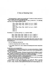
A Note on Hamming Code. The Hamming code is a powerful error correcting
code. It enables us to detect errors and to recover the original binary word if one ...
The theory of error correcting codes says that you can do it. In fact, this problem is
solved by the. Hamming code of length 7, with 4 information bits [2]. However ...
The receiver calculates the code based on the incoming bits and compares it with ... always detect (dmin â 1) errors, but can only correct half of ... information bits are needed. i.e, We ... provide redundant bits in the generated code, though the
conversations in digital domain, in which messages are encoded .... popularity in recent years due to lower and cheap product .... Register Transfer Level Views.
and the receiver. As the name implies, ... transmitted to a receiver, which uses a suitable decoder to .... from the des
ECE 6606 - Coding Theory and Applications. Modifications of a Hamming Code.
Initial code Consider the [7,4,3] Hamming code with generator and parity check ...
parallel dynamic programming on GPU and achieved the speed-up by a factor .... 4 GPU-accelerated Dynamic Programming ... using OpenCV calibration toolkit.
Jan 17, 2007 - C. Yao is with Department of Electronics Engineering, National Chiao-Tung. University ... P. K. Varshney is with the Department of Electrical Engineering and ..... ties of concerned block codes, error-free transmission of these.
Apr 13, 2014 - for instance, gradually translated the products to online- digitalized stores. ... research [1â6], and digital signature [7â10], dedicated to solve these problems. ... The main goal of robust watermarking is to make the embed-.
In data communication system reliability and efficiency of data transmission are important issues. ... correction techni
Abstract: In this paper a novel algorithm which is based on hamming code ... relevant edge pixels and replace with L bits of payload message. ... transmitted conveniently over the Internet. ... used in steganography technique [1, 2, 5, 8, 16]. 3. ...
Hamming code is an error correction code that can be used to detect single and double-bit errors and correct single-bit errors that can occur when binary data is ...
Nov 9, 2013 ... introduced a magic trick based on properties of the Hamming code. Here we
improve upon the trick, al- lowing the magician to predict both.
Hamming Codes. James Fiedler. Fall, 2004. In the late 1940s Richard Hamming
recognized that the further evolution of computers required greater reliability, ...
location of the bit in error. Once the bit is. identified, the receiver can reverse its value and. correct the error. Pa
Error-Correcting Codes. 7. Block & Linear Block Codes. 9. Introduction. 9.
Generator and Parity Check Matrix. 10. Syndromes. 10. The Hamming Code. 11.
Oct 10, 2011 - of the signal x and a Bernoulli distribution, which can be uniquely ..... Bernoulli trials defined in (2), there are j trials return si = â1, we can ...
Chapter 4. Hamming Codes. In the late 1940's Claude Shannon was developing
information theory and cod- ing as a mathematical model for communication.
Nov 6, 2015 - Jennifer Gillenwaterâ , Rishabh Iyerâ , Bethany Luschâ, Rahul Kidambiâ , Jeff ... lists, the measure of diversity is key to ensuring meaningful ...
properties of the "Generalized Hamming distance", and illustrate its use in the area of ... robots to test the measure's effectiveness in relating similar bitstrings. ... when a message, typically a sequence of bits, is sent between its source and de
and many researchers have done a lot of research in this area (Chang and ... The (n, n â k) Hamming code uses n cover bits to transmit n â k message bits, and the other k bits used for error correcting purpose are called par- .... There are 16 ele- ... u à HT, where 0 ⤠v ⤠15, H is the parity check matrix of the (7, 4) Hamming.
Cao et al. SpringerPlus (2016) 5:175 DOI 10.1186/s40064-016-1818-0
Open Access
RESEARCH
High capacity data hiding scheme based on (7, 4) Hamming code Zekun Cao1, Zhaoxia Yin1,2*, Honghe Hu1, Xiangping Gao1 and Liangmin Wang1 *Correspondence: [email protected] 1 Key Laboratory of Intelligent Computing & Signal Processing, School of Computer Science & Technology, Anhui University, Hefei 230601, Anhui, China Full list of author information is available at the end of the article
Abstract Aiming to embed large amount of data while minimize the sum of costs of all changed pixels, a novel high capacity data hiding scheme based on (7, 4) Hamming code is realized by a family of algorithms. Firstly, n (n = 1, 2, 3) cover pixels are assigned to one set according to the payload. Then, 128 binary strings of length seven are divided into eight sets according to the syndrome of every binary string. Binary strings that share the same syndrome are classified into one set. Finally, a binary string in a certain set determined by the data to be embedded is chosen to modify some of the least significant bits of the n cover pixels. The experimental results demonstrate that the image quality of the proposed method with high embedding payload is superior to those of the related schemes. Keywords: Data hiding, Hamming code, Image quality, Embedding capacity
embedding capacity got increased to be (k + 1)/2k bpp. Later, Chang et al. proposed a new scheme (Chang and Chou 2008) based on the idea of classification in 2008. Binary strings were assigned into eight sets. A binary string of length 2k − 1 in a specific set was selected out to embed k bits. It presented a new idea in applying Hamming code to data hiding. But the embedding capacity didn’t get improved compared with the previous two scheme. It is equal to the embedding capacity of the matrix encoding scheme (Crandall 1998). The marked-image quality of the aforementioned schemes is ideal when the embedding payload is low (no more than k/(2k − 1) or (k + 1)/2k bpp), but it degrades hardly with the increase of the embedding payload. Against this problem, a new data hiding scheme based on (7, 4) Hamming code is proposed in this paper. The marked-image quality of the proposed scheme is superior to those of the related works in Crandall (1998), Zhang et al. (2007) and Chang and Chou (2008) under a high embedding payload.
Related works The Hamming code
An error correcting code could not only detect that errors have occurred but also locate the error positions. Hamming code is a linear error correcting code that can detect and correct single bit errors. The (n, n − k) Hamming code uses n cover bits to transmit n − k message bits, and the other k bits used for error correcting purpose are called parity check bits, where n = 2k − 1 on the binary filed. S = {C1, C2, …,CM} is a set of code words. The number of elements of S, denoted as |S|, is called the cardinality of the code. For any two code words x = (x1, x2, …, xn) ∊ S and y = (y1, y2, …, yn) ∊ S, the Hamming distance is defined by dH(x, y) = |{i|xi ≠ yi}|. The minimum distance of the code S is defined as dmin = min {dH(x, y)|x, y ∊ S}. And the covering radius of the code S is r if any binary string u = (u1, u2, …, un) differs from at least one code word x = (x1, x2, …, xn) ∊ S in at most r positions. The minimum distance dmin measures the error-correcting capability, and the maximum distortion that occurs when a binary string is replaced by a proper code word is measured by the covering radius r. Therefore, a large value of the minimum distance dmin is preferable to the purpose of error correction whereas a small value of the covering radius r is preferable to the purpose of steganography. The (7, 4) Hamming code is a binary code of length n = 7, with cardinality |S| = 16, minimum distance dmin = 3, and covering radius r = 1. The (7, 4) Hamming code is now taken as an example to demonstrate how Hamming code correct an error bit. Suppose that the message bits are m = (1010). First, the code generator matrix G is used to form n cover bits C as follows.
1 0 C = m × G = (1010) × 0 0
0 1 0 0
0 0 1 0
0 0 0 1
1 1 1 0
1 1 0 1
1 0 = (1010010) 1 1
Next, the code word C is transmitted to a receiver via a noise communication channel. Supposed that the received code word is C′ = (1011010). Then the parity check matrix H is used to compute the syndrome vector z = (z1 , z2 , z3 ) for checking an error as follows.
The vector z T = (011)T is identical to the fourth column of the parity check matrix H. Thus, an error is detected at the fourth position of C′, and C′ is corrected by C′ = C′ ⊕ e4 = (1010010), where ⊕ is the exclusive-or operation, and ei, the error pattern, is a unit vector of length n with a “1” located at the i-th position. If the syndrome vector is z = (000), the receiver can conclude that no error has occurred. “Matrix Encoding”
In the matrix encoding scheme, a string of k bits s = (s1 , s2 , . . . , sk ) is embedded into a group of n cover pixels by adding or subtracting one to or from at most one cover pixel, where n = 2k − 1. Firstly, the syndrome vector z = (z1 , z2 , . . . , zk ) is calculated by z = (c × H T ) ⊕ s, with c = (LSB(p1 ), LSB(p2 ), . . . , LSB(pn )) and LSB (pi) means the least significant bit of i-th pixel pi. H is the parity check matrix of the (n, n − k) Hamming code. T is the transpose operation, and ⊕ is the exclusive-or operation. Next, if the computed syndrome vector z is (0, 0,…, 0), then the group of n marked pixels R is set to be equal to c; otherwise, find the i-th column of H that is equal to the transposed syndrome vector z T. The group of n marked pixels R is calculated by R = ei ⊕ c, where ei is a unit vector of length n with “1” located at the i-th position. At the receiving side, a receiver can extract the original binary string s from the received group R by s = R × H T . “Hamming+1”
Zhang et al. proposed the “Hamming+1” scheme (Zhang et al. 2007) to embed a string of (k + 1) secret bits s = (s1 , s2 , . . . , sk+1 ) into a group of (n + 1)ψ cover pixels p = (p1 , p2 , . . . , pn+1 ), where n = 2k − 1, by modifying at most one cover pixel as follows.
(s1 , s2 , . . . , sk ) = (LSB(p1 ), LSB(p2 ), . . . LSB(pn )) × H T ) sk+1 =
p 1
2
+
p 2
2
+ ··· +
p n
2
+ pn+1 mod 2
(1) (2)
where H is the parity check matrix of the (n, n − k) Hamming code, T is the transpose operation. This means that the first kψ secret bits of s are embedded into the first n bits of p by using matrix encoding, and the last secret bit of s is embedded by using the function of nψ cover pixels p. The embedding rules proposed in (Zhang et al. 2007) are as follows. If Eq. (1) does not hold, then pn+1 is kept unchanged, and one cover pixel pi (1 ≤ i ≤ n) needs to be increased or decreased by one to make Eqs. (1) and (2) hold simultaneously. If (1) holds and (2) does not, the first n pixels are kept unchanged and last cover pixel pn+1 is randomly increased or decreased by one. At the receiving side, a receiver can extract the first kψ secret bits of s by applying the extracting way of the matrix encoding scheme and the last secret bit of s can be extracted by using Eq. (2).
Cao et al. SpringerPlus (2016) 5:175
Page 4 of 13
“Nearest Code”
In the nearest covering code scheme (Chang and Chou 2008), all possible combinations of seven bits are classified into eight sets G0, G1, …G7. There are 16 elements G 0u , G 1u , . . . Gu15 in each set Gu, where 0 ≤ u ≤ 7. And G vu satisfies equation u = G vu × H T, where 0 ≤ v ≤ 15, H is the parity check matrix of the (7, 4) Hamming code, T is the transpose operation. A covering code G vs with nearest Hamming distance to P = (LSB(p1 ), LSB(p2 ), . . . , LSB(p7 )) is selected in G s according to secret bits s = (s1 , s2 , s3 ), where the subscript of G s is equal to the corresponding decimal number of s = (s1 , s2 , s3 ). Then, the cover pixels are modified by G vs. At the receiving side, a legal receiver can extract the original secret bits s from the received group of 7 pixels R by s = R × H T.
The proposed scheme In the proposed scheme, a secret binary string of length three is in a mapping relationship with the error pattern of the (7, 4) Hamming code and then can be embedded into a group of cover pixels. The number of the cover pixels in different groups varies under different embedding payload. The preparations
I is the cover image sized H × W, and marked_I is the marked-imagewith data 1 1 1 0 1 0 0 D = {d1, …, dL}embedded, where di ∊ {0, 1}, 1 ≤ i ≤ L. H = 1 1 0 1 0 1 0 is a parity 1 0 1 1 0 0 1
check matrix of the (7, 4) Hamming code. A string of binary bits (b1b2…b7) is the cover of a string of three bits (didi+1di+2), and (b1′ b2′ . . . b7′ ) is the marked-string of (b1b2…b7). pi is the i-th pixel in cover image, and pi′ is the i-th pixel in marked-image. pji represents the j-th least significant bit of pixel pi. ER, i.e. embedding rate, is calculated as follows.
ER =
L bpp H ×W
(3)
Nn is the number of groups that n (n = 1, 2, 3) cover pixels are used to embed a three bits string. And Nn satisfies Formula (4). The first equation of Formula (4) indicates that the number of bits to be embedded is equal to the amount of bits the cover image could bear under a particular embedding rate. And the second equation in Formula (4) requires that the cover pixels we need are less or equal to the pixels the cover image could provide. 3(N1 + N2 + N3 ) = H × W × ER (4) N1 + 2N2 + 3N3 ≤ H × W To modify the cover pixels as less as possible, Formula (4) is processed to obtain Formula (5) based on the following considerations. The top priority scheme, grouping three cover pixels together to embed a three bits string, satisfies Formula (4) when 0 ≤ ER ≤ 1. When 1