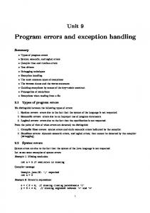
Handling Ambiguity and Errors: Visual Languages for Calligraphic Interaction JOÃO PAULO PEREIRA1 2 MANUEL JOÃO FONSECA JOAQUIM ARMANDO PIRES JORGE2 1 ISEP – Instituto Superior de Engenharia do Porto, Porto, Portugal
[email protected] 2 INESC – Instituto de Engenharia de Sistemas e Computadores – Rua Alves Redol, 9, 6º 1000-029 Lisboa, Portugal {jaj,mjf}@inesc.pt Abstract. This paper describes error handling and ambiguity in a class of applications organized around drawing and sketching, which we call Calligraphic Interfaces. While errors and imprecision are unavoidable features of human input, these have long been considered nuisances and problems to circumvent in user interface design. However, the transition away from non-WIMP interface styles and into continuous media featuring recognition requires that we take a fresh approach to errors and imprecision. We present new tools and interaction styles to allow designers to develop error tolerant and simpler interaction dialogues.
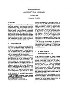
1 Introduction Recognition-based interfaces have made significant progress over the last few years due to advances in affordable computing power. The advent of mobile devices and new interaction modalities looks poised to provide viable alternatives to pervasive WIMP-based desktop applications. Nevertheless, integral use of sketches, pen strokes and gestures in computer interfaces is still restricted, because gestures are difficult for computers to analyze. While handwriting and speech recognition have been active research topics for thirty years, they still pose serious problems. Gestures are so different from conventional input modalities that they demand radically new methods for input handling and dialogue design. Pen stroke data are hard to classify due to noise and user variations, requiring pattern recognition techniques to convert them into more tractable form. Even the best recognizer will sometimes give different interpretations of input that human observers perceive as similar. This problem is compounded by the difficulty in using contextual information (other than a dictionary) to aid in recognition. To overcome these limitations, new approaches, which we call Calligraphic Interfaces, use sketching and drawing as the main organizing paradigm. Such applications rely on continuous input modalities rather than discrete interactions characteristic of WIMP. The word “calligraphy'' comes from the Greek kalligraphia formed by the composition of kallos (= beautiful) and graphein (= to scratch, draw or write). It stands for beautiful or expert handwriting, or simply handwriting, and in a broad sense, denotes the art of fine hand drawing. However, replacing direct manipulation by sketching does not provide a definitive answer. While the
temptation to follow the paper-and-pencil metaphor is great, free-hand sketch recognition remains an elusive goal. Further, using gestures and sketches to enter commands and draw shapes requires users to learn a command set – sketches do not enjoy the self-disclosing characteristics of menus. Moreover, the imprecise nature of interactions presents additional problems that are not adequately addressed by present-generation multimodal interfaces. In this paper we address the three problems outlined above through a combination of different paradigms: a sketching metaphor provides a paper-andpencil like interaction. A kind of dynamic menus – expectation lists – tries to expose the state of the application without interfering with the task. Finally incremental drawing paradigms based on visual languages allows precise drawings to be progressively constructed from sketches through constraints and parsing. We present our work on two different domain areas to support our points. In the first section we describe DocSketch, a calligraphic interface to input document layout by means of freehand sketches. Next, we present our work on Gesture-based Incremental Design Systems (GIDeS), which embodies the incremental drawing approach coupled with expectation lists. Both systems extend the paper and pencil paradigm in novel and interesting ways. While these are still emerging applications, suffering from many infancy troubles, they differ sufficiently from the current paradigm to allow us a glimpse at what we think are some fundamental traits of post-WIMP applications. 2 Related Work The idea of calligraphic interfaces is not new. In fact, communication through sketches and planar diagrams precedes the invention of writing by more than 30
centuries. Also, using pen-based interfaces in tasks related to the automatic recognition of hand written or drawn information is over a generation old. However, it did not make significant progress for three major reasons: early gesture recognition systems had had low recognition rates; dealing with the ambiguity inherent to human-provided information was not easily solved; and the advent of easy-to-use direct manipulation WIMP interfaces led to a widespread lack of interest for gesture-based interfaces. In 1963, Sutherland presented Sketchpad [25] the first interactive system that used one light pen to draw diagrams directly over the screen surface. The main limitation of this system was in the recognition capabilities, limited resources and high cost of the computer used. Landay [24] describes a sketch-based approach for the early stages of user interface design. His work uses electronic sketching to allow designers to quickly record design ideas in a tangible form, obviating the need to specify too much detail too early in the process. His electronic sketches possess the advantages normally associated with computer-based tools, making them well suited to user interface design. Sketch [23] is an example of a system that allows users to create 3D scenes based on CSG-like primitives instantiated by 2D strokes. All interaction relies on a three-button mouse, occasionally combined with modifier keys on the keyboard. Sketch uses two types of gestural elements – five classes of strokes (draw while pressing the first mouse button) and two classes of interactors (made with the second button). Camera manipulation is performed with the third mouse button. Another feature of Sketch are direction dependent gesture strokes to infer CSG operations. Zeleznik’s et al. work has proceeded with Jot [9], an extension to Sketch’s interface that relies not only on pen input but also on immersive virtual reality technology such as sixdegrees-of-freedom physical props and stereo glasses. Our approach differs from Sketch’s in three main ways. First, GIDeS uses a stylus for all operations. Second, except for camera manipulation, which uses the side button, all commands, drawing and 3D primitives are inferred only from the available (drawn) information. Lastly, all gestures are independent of direction, relying on perspective to retain the pencil-and-paper flavor. Encarnação et al. [5,7] developed a system that combines traditional desktop metaphors with a virtual reality interface. This allows the user to directly create
simple objects in true 3D, through the use of iconic gestures that resemble the contours of the top-down projections of objects. Their system uses very sophisticated equipment such as transparent pen and pad, shutter glasses, magnetic trackers and a virtual table display device. Igarashi et al. developed Teddy [12], a system that allows modeling of freeform 3D objects from sketched 2D outlines. However, resulting models are constrained to a sphere-equivalent topology and Boolean operations were not taken into account. Igarashi et al. describe a technique for rapid geometric design called interactive beautification [11]. Freehand strokes drawn by users are converted by their system – Pegasus – in line segments that must satisfy certain geometric constraints such as perpendicularity, congruence and symmetry amongst others. Pegasus also uses context information to deal with ambiguity. It generates multiple candidates by combining inferred constraints appropriately and evaluates them in order to find the most plausible ones and reject the others. The user is then allowed to select the candidate that meets his or her wishes by tapping on it directly. The procedure is completed as soon as the user taps outside the candidates or draws the next stroke. As the authors say, the problem with this way of handling ambiguity is that it is difficult for users to perform the selection they want amongst a large number of overlapping candidates. Mankoff et al. [16] present a survey on interfaces that make use of various forms of recognition such as gesture, handwriting and speech interpretation. Their work also focuses on the problem of handling recognition errors and ambiguity by means of dialogues between the system and the user – a process they call mediation. Based on that survey, the authors created a user interface toolkit called OOPS – organized option pruning system [15]. OOPS consists of a library of reusable mediation techniques combined with architectural solutions to model and provide support for ambiguity at the level of user input events. Gross et al. [10], Back of an Envelope (BoE) project applies pen-based interfaces to a wide range of domains such as databases, simulation programs and 3D modeling. Their approach tries to combine the virtues of highly structured interfaces for creating accurate drawings and models with the benefits inherent to freehand drawing interfaces.
Turner et al. [22] designed Stilton, a sketch modeling system that resembles a desktop VRML browser, allowing users to interact with a 3D model in perspective projection, or panoramic photographs mapped onto the scene as a “floor” and “walls”. The system can be used to reconstruct geometry from panoramic images or to add new objects to an existing scene. Object creation relies on geometric information sketched by users on an imaginary 2D drawing plane. While most of the approaches outlined above explicitly use sketches and drawing as a novel organizing paradigm, ambiguous input and recognition errors are considered nuisances and hurdles to overcome. In most approaches, explicit formal syntactic analysis is not addressed. Ambiguity is handled for misrecognized constituents through hard-coded confidence values in some cases and in ad-hoc manner in others, with the notable exception of Mankoff’s work. Visually ambiguous arrangements concerning spatial relationships are also not treated. Error recovery is user dependent and requires dialog boxes not consistent with the hand-drawn philosophy of most approaches. The hard-coded nature of the rules also limits the system flexibility in extending and changing the visual language. We will present several avenues to attack this problem in what follows. At the lowest level we present CalI, a set of software components to address stroke recognition. At a level above we discuss ambiguous visual arrangements and present fuzzy visual languages used in DocSketch [18] a page composition program. Finally, at the three-dimensional level we discuss expectation lists, reduced-instruction set interfaces and the judicious use of constraints to transform imprecise input into rigourous three-dimensional drawings using GIDeS.
3 CALI -A Library for 2D Gesture Recognition In this section we present CALI [3], a software library for the development of Calligraphic Interfaces, centered mainly on a simple Shape Recognizer. The Recognizer [4] is a fast, simple and compact approach to identify Scribbles (multi-stroke geometric shapes) drawn with a stylus on a digitizing tablet. The method is able to identify shapes of different sizes and rotated at arbitrary angles, drawn with dashed, continuous strokes or overlapping lines. The recognition process is based on three main ideas. Firstly, it uses entirely global geometric properties extracted from input shapes. Since we are mainly interested in identifying geometric entities, the recognizer relies mainly on geometric information. Secondly, to enhance recognition performance, we use a set of filters either to identify shapes or to filter out
Figure 1: Multi-stroke and uni-stroke shapes.
unwanted shapes using distinctive criteria. Finally, to overcome uncertainty and imprecision in shape sketches, we use fuzzy logic to associate degrees of certainty to recognized shapes, thereby handling ambiguities naturally. This algorithm recognizes elementary geometric shapes, such as Triangles, Rectangles, Diamonds, Circles, Ellipses, Lines and Arrows, and five gesture commands, Delete, Cross, WavyLine, Move and Copy, as depicted in Figure 1. Shapes are recognized independently of changes in rotation, size or number of individual strokes. Commands are shapes drawn using a single stroke, except Cross, which requires two strokes. The recognizer works by looking up values of specific features in fuzzy sets associated to each shape and command. This process yields a list of plausible shapes ordered by degree of certainty.
Figure 2: Sketched document layout example.
The set of shapes selected and presented in Figure 1 are the basic elements to construct technical diagrams, such as electric or logic circuits, flowcharts or architectural sketches. These diagrams also require distinguishing between solid, dash and bold depictions of shapes in the same family. Some authors notice that the majority of diagrams were built of ellipses, rectangles and lines [1]. Another author [2] has found that designers use a small set of symbols and that they share drawing conventions, so there is coherence between symbols used by different designers. The recognizer has a recognition rate of 96%. It is fast: each scribble requires, on average, less than 50 ms (using a Pentium II @ 233 MHz) to be recognized, from feature vector computation to final classification. The fast response characteristic makes it very usable in interactive applications. This approach extends and improves Kimura's work [1], which recognizes a small number of shapes and did not distinguish rotated, open/closed, dashed and bold shapes. 4 Example Application: Document Layout This section describes an example interaction scenario using the DocSketch system to design a document layout. Figure 2 shows an example that can be used to produce an HTML page like that in Figure 3. In Figure 2 the user has drawn five types of design elements: three headers, one scrolled window with a vertical scroll bar to the right, one image, one label and several buttons. These are the main construction elements and respective spatial arrangements shown in this example. The system is responsible for inferring the most likely document layout, an example of which appears in Figure 3. This way, DocSketch enables the designer to focus on the exploration of design ideas and not on details.
Figure 3: CNN weather forecast page.
The interaction sequence starts when the user sketches shapes to compose a document layout, using a pen on a digitizing tablet. The system tries to identify each shape as soon as it is drawn, using the recognizer described above. After identifying a shape, the system tries to combine it with previously inserted shapes, using basic spatial and adjacency fuzzy relations. This information about shapes and relations is then fed to a rule--based system, which uses basic knowledge about the structure and patterns of document layout to infer, which design element was intended. The inference rules of this system are grouped into a grammatical specification of a visual language for document design. Since each rule also gets associated degrees of certainty computed from its components, the system is naturally guided to infer the most likely document design constituents. DocSketch allows users to manage design components through the usual commands Delete, Move and Copy, which are supported and recognized as gestures. The visual elements used to define the types of typographic operators, their positions and dimensions, as well as other visual characteristics make up a visual language for document design. In this visual language symbols are sketches built by composition of simple shapes from a subset of those presented in Figure 1. A visual grammar defines rules of composition of individual elements as described in [18].
Figure 4: Ambiguous visual arrangements
5 Visual Ambiguity One of the problems with identification of hand drawn sketches is the ambiguity between visually related shapes. Ambiguity exists, for instance, between Rectangles and Diamonds, Ellipses and Circles, Lines and Text (WavyLines), as exemplified by Figure 6. Composing geometric shapes using visual relationships and constraints illustrates another source of ambiguity. Quite often the evaluation of unary predicates that inspect shape properties yields ambiguous results. For example, we use the slope of a line to classify it as vertical, oblique or horizontal. It is easy to see how this classification can be ambiguous. Figure 5 shows some lines. Which of those can be definitely classified as horizontal, vertical or oblique? Ambiguous arrangements can also happen with visual relationships between shapes. One example is the Near relation used to assess proximity. This example shows how expressions in visual languages may be ambiguous. When building up visual arrangements composed upon shapes closely located it is often difficult to know which ones are to be combined when more than one combination is possible. Figure 4 shows a scroll bar that can be associated either with the left window or with the right window. Humans solve the natural ambiguity associated with individual visual symbols, its properties and its arrangements, by identifying more than one possible characterization and using context or feedback from
Figure 5: Ambiguous visual constraints
Figure 6: Ambiguity in sketched shapes. other people to select one interpretation. Our approach deals with visual ambiguity in a similar way, i.e. when it is not possible to identify univocally a shape or a composition, the recognition subsystem returns a list of possible candidates. The application can then choose the “best'' candidate using context information. When identifying geometric shapes, our stroke recognizer models classification ambiguities between shapes using fuzzy logic to associate degrees of certainty to each shape according to its attributes. In what concerns spatial relations and arrangements, we handle visual ambiguity through Fuzzy Relational Adjacency Grammars [13] that combine fuzzy logic with spatial relations. This allows us to assign degrees of likelihood to each spatial arrangement and decide on the “best” candidate. 6 Error Handling When recognizing shape composition, we use a compatibility matrix to enable considering the compatible types of simple shapes. This way we provide a simple and effective error recovery mechanism. This is an approach to produce document designs, not to draw geometric shapes. However, document design support depends on simple geometric shape recognition. Therefore, the errors produced by the shape recognizer will have to be treated so the process can continue. We can handle mis-recognized symbols either by requiring users to manually input the correct classifications or by trying alternative likely variations automatically. We decided to address error situations using the latter approach. Still, users can delete a non-recognized shape or ask for the “next most likely candidate" by issuing a Cross gesture. The stroke recognizer provides an ordered list of candidates for this purpose. While this solution has proven to be effective it is less usable than expectation lists, a device, which we will discuss in the next section. Another useful heuristic for handling recognition errors is a degree of compatibility. According to the following compatibility matrix,
(compatible, Diamond, Rectangle, 0.60) (compatible, Ellipse, Rectangle, 50) (compatible, Circle, Rectangle, 0.40) (compatible, Line, Text, 0.60)
when the analyzer receives a Diamond from the recognizer, if it is not capable of producing any composition, it will try to proceed by substituting that shape for a Rectangle. In the same spirit we can define Ellipse and a Circle as shapes compatible, to an extent with Rectangle. The last item specifies a substitution for Line, but in this last case, a symbol of type Text will replace it. This compatibility relation defines a degree of conformance between shapes. The degree of likelihood of the ``new" shape is defined by the minimum between the degree of conformance and the degree of likelihood assigned by the recognizer to the shape being substituted. 7 GIDES: Sketching in Three Dimensions In the previous section, we have seen grammatical, visual and heuristic ways with handling visual ambiguity in two-dimensional compositions. In the following sections we will present GIDeS, a calligraphic interface to create three-dimensional models. The architecture of GIDeS calligraphic interface consists basically of a set of three gesture recognition subsystems, an expectation list generator and a set of constraint-based interaction modes that allow users to perform geometric transformations and cuts on objects.
Figure 7: Primitives in GIDeS recognize line segments, polylines, circles, ellipses and generic curves represented as cubic splines. The recognition system is capable of learning and adapting to a user’s drawing style, since the distinction between smooth and non-smooth strokes relies on a parameter that changes dynamically according to the success or failure of previous interpretation attempts.
Figure 8: Expectation Lists 8 Gesture Recognition Command gesture interpretation relies on two recognition subsystems. The first one is an improved version of Rubine’s trainable recognizer [21], combined with ours [3] to add some new features: • Support for multiple-stroke gesture recognition. The sequence by which strokes are drawn is irrelevant. • Recognize strokes regardless of direction. • Force recognition to depend on context aspects not necessarily related to gesture geometry. • Support for handling ambiguity. A detailed description of the changes we made to Rubine’s algorithm can be found in [17]. Three-dimensional primitive instantiation relies on a second recognition subsystem that takes into account both the topology and geometry of each gesture. A detailed description of this recognizer can also be found in [17]. The third recognition subsystem is responsible for interpreting linear strokes and to decide whether these strokes shall be interpreted as polylines or curved (smooth) drawing elements. This subsystem can
9 Expectation Lists For gesture recognition systems to work adequately we need to strike a compromise between two extremes. On one hand the interpretation of strokes must be flexible enough to deal with uncertainty, otherwise the rate of incorrectly rejected gestures (we call them false negatives) will be high. On the other hand recognition must be rigid enough to provide selectivity and to reduce the rate of erroneously interpreted gestures (false positives). Our approach based on the combination of gesture recognition with expectation lists changes this paradigm. Instead of trying to find some heuristic (heuristics, no matter how good they are, are always subject to failure due to human unpredictability) that selects the most probable candidate and rejects all others in order to avoid ambiguity, we made our recognition systems more tolerant than usual to gesture uncertainty and use expectation lists as dynamic menus to allow users to exercise control and choose amongst the most likely candidates. In other words we have significantly reduced the false negative rate and, since the options presented to users by expectation lists are mere suggestions, the corresponding increase of false positives is not a
a) erase Figure 9: Drawing Expectation List problem, because users can simply ignore these suggestions in the same way they ignore other unwanted options. That is, instead of trying to avoid ambiguity, we encourage its occurrence and explore it to user’s benefit. We have tried to extend expectation lists to all levels of user interaction. With the exception of command expectation lists that use icons to make suggestions, all lists prompt the user with small-scale models of the objects that can be created in relation to the existing context. For example, Figure 10 shows how expectation lists can significantly reduce the number of needed command gestures, thus minimizing cognitive load on users. In this case two commands – delete and apply texture – share the same “scratch” gesture. The difference is that the delete stroke must cross the object boundary (Figure 10a), while the texture stroke must be entirely drawn over the object’s surface, i.e. inside its two-dimensional projection (Figure 10b). The user may also opt to delete or conversely, to apply a texture to a previously selected object. In that case GIDeS does not have enough contextual information to identify what command to apply. Therefore, the application generates a command expectation list and prompts the user to select a command (Figure 10c). Figure 9 shows an example of a 3D primitive expectation list. Again notice how our interface explores ambiguity in order to reduce the required repertoire of recognized gestures. In this case the same idiom can instantiate four distinct objects, namely a truncated cone, a surface of revolution – the most obvious choices – and two less evident kinds of cylindrical sections with different orientations. The designer may also ignore the suggested options and continue drawing, in which case no implicit commands will be performed. This is consistent with the principle of least intrusion and user control. As we have seen in this section, our system presents an innovative approach as compared to traditional CAD systems by using a mixed metaphor – while we try to stay close to interaction modalities evocative of the paper-and-pencil organizing principles, we use an incremental drawing approach to allow draftspeople to use sketching gestures to construct rigorous models through a judicious combination of simple, yet powerful commands and constraints to allow users to perform more complex operations with fewer commands.
b) texture
c) ambiguous
Figure10: Command Expectation List While some of the techniques developed here have been tried in other contexts, we believe that the combination of three basic interaction paradigms bears the promise to provide highly flexible and powerful design systems. In developing our approach we have applied a consistent set of organizing principles throughout the drawing application: a) Calligraphic Recognition as a foundation to our drawing paradigm. This allows draftspeople to apply the pencil-and-paper metaphor for creating base objects. Calligraphic recognition combined with incremental, drawing can allow powerful operations to be carried out through sketching on objects as illustrated by Figure 13. b) Expectation lists make the system state and functionality self-disclosing. Moreover expectation lists make it possible to deal with imprecision and recognition errors in an elegant and graceful manner. c) Incremental Drawing makes it possible to gradually refine a drawing by implicit constraint satisfaction. To this end we have replaced explicit placement and adjustment commands by approximate manipulations afforded by gestures and using constraints to achieve final (rigorous) placement. Moreover, constraints can be and are used to determine the geometric attributes of newly created primitives if those can be obtained from context. For example, sketching an ellipse on top of a cylinder automatically makes the ellipse take on the cylinder’s diameter. The user can then validate this option interacting with the dynamic expectation list. d) Using constraint satisfaction replaces explicit commands with approximate manipulation operations. Constraint satisfaction is a powerful control mechanism. We use it implicitly on the constrained positioning (adjust) and assembly (glue) command modes described above. We believe that matching on approximate constraints and then incrementally adjust the image so that these can be met can replace many explicit commands commonly used in CAD systems for the same purpose. Often designers spend precious time adjusting details in a technical drawing to ensure that certain constraints are met. Constraint satisfaction coupled with sketched intentions makes it possible to achieve the same result in a simpler manner. Figure 13 illustrates this point where the system applies coaxial and coplanar constraints to adjust the cylinder just created to an existing object.
Figure 11: Implicit Coplanar constraints e) Reducing instruction set and command usage. The conjugation of the mechanisms outlined above can result in more concise and expressive user interfaces. Reducing instructions can in theory improve learnability and minimize cognitive load. We need to use expectation lists judiciously to expose functionality in a flexible manner, however. Figure 12 illustrates this principle, as well as figure 14. Instead of requiring the user to enter some special mode, GIDeS tries to interpret user sketches in context, to allow executing complex actions via simple commands. In the case depicted in Figure 12, we save entering some special mode to correct a curve already entered. Just drawing over suffices to change the contour, sparing the user from complicated interactions. As we have seen in this section, our system presents an innovative approach as compared to traditional CAD systems by using a mixed metaphor – while we try to stay close to interaction modalities evocative of the paper-and-pencil organizing principles, we use an incremental drawing approach to allow draftspeople to use sketching gestures to construct rigorous models through a judicious combination of simple, yet powerful commands and constraints to allow users to perform more complex operations with fewer commands. Figure 15 exemplifies a reasonably complex object drawn using GIDeS.
Figure 13: Coplanar and coaxial constraints below shows the measured times, number of commands, strokes (mouse clicks) in GIDeS as compared to a conventional CAD system in creating one of the objects depicted in Figure 15 (Task 1), after a brief tutorial describing the functionality of our system. Task 2 consisted in drawing the object depicted in Figure 16. Task
CAD GIDeS Time Cmds Time Strokes Task 1 407,5 73 225 48 Task 2 190 45 223 22 The results show mixed performance of our system relative to a more mature product. While drawing objects with axial symmetry seems the kind of task where GIDeS has the potential to excel, using a mouse greatly limited performance and had a negative impact on user satisfaction. In this light, the results seem moderately encouraging. Users pointed out several limitations such as the lack of an undo command (not implemented yet) but the calligraphic model of interaction elicited enthusiastic responses from participants except one who stated a strong preference for the conventional CAD approach and a negative attitude towards our system.
While some of the techniques developed here have been tried in other contexts, we believe that the combination of three basic interaction paradigms bears the promise to provide highly flexible and powerful design systems. Figure 14: Rounding corners on 3D Objects
Figure12: Change contour by sketching over 10 Preliminary Evaluation We asked five users familiar with traditional CAD systems to draw some objects using our system and their system of choice with direct manipulation commands, using a mouse rather than a tablet and stylus combination due to logistics-related problems. Table
11 Conclusions and Future Work In this paper we have presented a novel set of approaches for creating geometric models and 2D drawings from sketches through Calligraphic Interaction. Our goal is to improve on the usability of current WIMP systems at the early stages of design. To this end we have proposed an approach based on Calligraphic Interfaces, Reduced Instruction Set and Constraints Mixing metaphors to model objects by incremental drawing. We have introduced expectation lists, a kind of dynamic menus to make our interfaces
easier to learn while showing users more of the system state. We believe this approach is highly suited for designing complex shapes and will be looking into expanding and augmenting the expectation lists to make our interface more self-disclosing. Preliminary results show a positive attitude from users and the promise to improve on traditional approaches via more flexible and expressive commands. We plan to explore more natural ways of combining constraints and error handling to improve dialogues in the near future. While the system shows promise, we feel that more attention to task and contextual user analysis will provide necessary insights to make our approaches more efficient and robust.
12 References [1] A. Apte, V. Vo and T. Dan Kimura, Recognizing Multistroke Geometric Shapes: An Experimental Evaluation, Proc. ACM UIST'93, pages 121-128, Atlanta, GA, 1993. [2] Ellen Y. Do, The right tool at the right time, PhD thesis, Georgia Institute of Technology, Sept. 1998. [3] Fonseca, Manuel J. and Jorge, Joaquim, CALI: A Software Library for Calligraphic Interfaces, available at http://immi.inesc.pt/~mjf/cali/, February 2001. [4] Fonseca, Manuel J. and Jorge, Joaquim, Using Fuzzy Logic to Recognize Geometric Shapes Interactively, Proc. of the Ninth IEEE Int. Conference on Fuzzy Systems, San Antonio, USA, 2000. [5] Bimber O., Encarnação L. M., Stork A. A multilayered architecture for sketch-based interaction within virtual environments. Computers & Graphics, Vol. 24, No. 6, pp. 851 – 867, Elsevier, Dec. 2000. [6].Branco V., Ferreira F. N., Costa A. Sketching 3D models with 2D interaction devices. EUROGRAPHICS '94 Conference Proceedings, Daehlen M., Kjelldahl L. (editors), Oslo, Blackwell Pub., pp. 489 – 502, 1994. [7] Encarnação L. M., Bimber O., Schmalstieg D., Chandler S. D. A Translucent Sketchpad for the Virtual Table Exploring Motion-based Gesture Recognition. Computer Graphics Forum, Vol. 18, No. 3, pp. C-277 – C-285, 1999. [8] Fonseca M. J., Jorge J. A. CALI: Uma Biblioteca de Componentes para Interfaces Caligráficas. Actas do 9.º Encontro Português de Computação Gráfica, pp. 93 – 100, Feb. 2000. [9] Forsberg A. S., LaViola Jr. J. J., Markosian L., Zeleznik R. C. Seamless Interaction in Virtual Reality. Computer Graphics & Applications, IEEE, Vol. 17, No. 6, pp. 6 – 9, 1997. [10] Gross M. D., Do E. Y.-L. Drawing on the Back of an Envelope: a framework for interacting with
application programs by freehand drawing. Computers & Graphics, Vol. 24, No. 6, pp. 835 – 849, Elsevier, Dec. 2000 [11] Igarashi T., Matsuoka S., Kawachiya S., Tanaka H. Interactive Beautification: A Technique for Rapid Geometric Design. Proceedings of the ACM Symposium on User Interface Software Technology (UIST), 1997. [12] Igarashi T., Matsuoka S., Tanaka H. Teddy: A Sketching Interface for 3D Freeform Design. SIGGRAPH ’99 Conference Proceedings, ACM, 1999. [13] Jorge J. A. Parsing Adjacency Grammars for Calligraphic Interfaces. PhD Thesis, Rensselaer Polytechnic Institute, Troy, New York, 1994. [14] Jorge J. A., Glinert E. P. Calligraphic Interfaces: towards a new generation of interactive systems. Jorge J. A., Glinert E. P. (guest editors), Computers & Graphics, Vol. 24, No. 6, pp. 817, Elsevier, Dec. 2000. [15] Mankoff J., Hudson S. E., Abowd G. D. Providing integrated toolkit-level support for ambiguity in recognition-based interfaces. Proceedings of ACM CHI’00 Conference on Human Factors in Computing Systems, pp. 368 – 375, 2000. [16] Mankoff J., Abowd G. D., Hudson S. E. OOPS: a toolkit supporting mediation techniques for resolving ambiguity in recognition-based interfaces. Computers & Graphics, Vol. 24, No. 6, pp. 819 – 834, Elsevier, Dec. 2000. [17] Pereira J. P., Jorge J. A., Branco V., Ferreira F. N. Towards Calligraphic Interfaces: Sketching 3D Scenes with Gestures and Context Icons. The 8-th International Conference in Central Europe on Computer Graphics, Visualization and Interactive Digital Media 2000, Plzen, Czech Republic, Feb. 2000. [18] Albuquerque Maria, Fonseca M João, Jorge Joaquim, Visual Languages for Sketching Documents, IEEE Symposium on Visual Languages and Computing, VL2000, Seattle, USA, 10-14 September 2000. [19] Pereira J. P., Jorge J. A., Branco V., Ferreira F. N. GIDeS: Uma Abordagem Caligráfica à Edição 3D. Actas do 9.º Encontro Português de Computação Gráfica, pp. 101 – 108, Feb. 2000. [20] Pereira J. P., Jorge J. A., Branco V., Ferreira F. N. Reduced Instruction Set Calligraphic Interfaces: Sketching Complex 3D Objects with (Fewer) Gestures. d3 desire designum design, 4th European Academy of Design Conference Proceedings, pp. 194 – 196, Aveiro, Portugal, April 2001. [21] Rubine D. Specifying Gestures by Example, SIGGRAPH ‘91Conference Proceedings, ACM, Vol. 25, No. 4, pp. 329 – 337, 1991. [22] Turner A., Chapman D., Penn A. Sketching space. Computers & Graphics, Vol. 24, No. 6, pp. 869 – 879, Elsevier, Dec. 2000.
[23] Zeleznik R. C., Herndon K. P., Hughes J. F. SKETCH: An Interface for Sketching 3D Scenes. SIGGRAPH '96 Conference Proceedings, ACM, Vol. 30, No. 4, pp. 163 – 170, 1996. [24] Landay J., Interactive Sketching for the Early Stages of User Interface Design, PhD Thesis, Carnegie
Figure 15: Example scene created with GIDeS
Mellon University, Computer Science, Pittsburgh – USA, 1996 [25] Sutherland I. E., Sketchpad: A Man-Machine Graphical Communication System, Spring Joint Computer Conference, pages 2--19, 1963, AFIPS Press
Figure 16: Object used in Benchmarks