edge points, filters out superfluous edge points for non- polygonal ... fabric's shape. After the image acquisition of the ... rotation of the robot around the needle, the needle- point is known in ... the next side coincides with the sewing line. The.
Visual servoing controller for robot handling fabrics of curved edges P.Th. Zachariaa, I.G.Mariolisb, N.A. Aspragathosa, E.S. Dermatasb a
Department of Mechanical & Aeronautics Engineering, Rion, Patras, Greece b Department of Electrical & Computer Engineering, Rion, Patras, Greece
Abstract This paper proposes a visual servoing manipulator controller to guide fabrics during the sewing process. The task of the end-effector is to handle a randomly located fabric on a table and feed it to the sewing needle along the desired seam. The proposed system is capable of handling fabrics having straight line edges and curved edges with arbitrary curvatures. The vision system identifies the type of the fabric edges and the system decides the procedure that should be followed, so that the fabric is successfully handled. The experimental results demonstrate the efficiency and the robustness of the proposed approach.
1. Introduction Fabric assembly involves complex operations in which human vision and manual dexterity are essential. Therefore, current industrial manipulators should be capable of manipulating limp materials, since the application of flexible automation to the textile industry is extremely beneficial. An automated machine system requires flexibility in order to handle various types and sizes of fabric and perform ‘sensitive’ operations such as sewing, where the fabric must be held taut and unwrinkled in order to obtain high seam quality. This is a really complicated procedure where vision and force sensors should be used in order to provide successful stitches, since the sewing process requires precision and quality. In addition, using Artificial Intelligence techniques, it is possible to successfully model problems that are afflicted with uncertainty, subjectivity, ambiguity and vagueness. Only a few researches [1,2,3] have worked on the automatic feeding of fabrics with curved edges into the sewing machine. E. Torgerson et al. [1] introduced a
method for the manipulation of various types of fabric shapes. The determination of robot motion paths is based on visual feedback defining the location of the fabric edges in world coordinates. The system detects the workpiece edge, determines the orientation of the edge points, filters out superfluous edge points for nonpolygonal shapes and computes some geometric parameters. Using these parameters, the coordinates of the robot path point is computed. The developed algorithm was proved to be effective for both polygonal and non-polygonal shapes, whereas the accuracy of the approximation to the desired seam line depends on the camera resolution. M.Kudo et.al [2] developed an automated sewing system comprised by two robots handling the fabric on the table. Visual information was used to control seam path and its deviation from the desired trajectory. Sewing along a curved line is achieved using the internal robot commands for straight-line motion and the visual servoing. The fabric is translated in the sewing direction and rotated about the needle according to the visual feedback information. These two actions were carried out simultaneously. Thus, the
commanded trajectory was a straight line, but the visual servoing system followed a paper pattern and the trajectory error was within ±0,5mm. S.Amin-Nejad et al. [3] developed a positionbased visual servoing system for edge trimming of fabric embroideries by laser. Two methods for seam trajectory generation were introduced. In the first method, the tracking trajectory is determined only by using the vision data, whereas in the second method, the predetermined path data is modified by the vision data. In their work, a tracking controller uses a feedforward controller in the tangential direction of the seam and a feedback controller in the normal direction. The method was implemented for three types of seam patterns: straight line, sinusoidal and circular. However, there is little work done in the field of robot sewing as far as arbitrary curved edges are concerned, but there is some work done in curve approaching in other fields. S.Omirou [4] presents an algorithm for cutter offsetting in CNC machining. The algorithm is based on the direction and proximity criteria. In each iteration, there are eight candidate fixed steps. The best step is the one that satisfies the direction criterion while, at the same time, it satisfies a criterion of proximity that expresses a measure of closeness to the offset. The experimental results presented approved the effectiveness and simplicity of the algorithm. Visual servoing is essential during the sewing process. The visual servoing systems are based on two basic approaches: position-based and image-based visual servo control [5]. In addition, there are the 2 1/2 D visual servoing systems, where a combination of the two aforementioned approaches is used and the error to be minimised is specified both in the image and the pose space. In the sewing process, the robotic handling target requires sophisticated control for the path determination of the cloth. In the present paper, the designed robot control system is based on artificial intelligence and visual servoing in order to handle uncertainty of the system. In this paper, a visual servoing controller is presented for handling during the sewing process. The system identifies the shape of the fabric and then a fuzzy controller guides the fabric to the sewing machine. The focus of this paper is the sewing of fabrics with edges of arbitrary curvature by approximating the curve with small straight-line segments. It is of great importance that the maximum deviation between the real and the desired seam line should be less than an acceptable limit, since seams
that do not meet this constraint are defective and the joined pieces can not be used for the final product. 2. The robot sewing process The proposed system is a combination of imagebased and position-based control system. The imagebased analysis is used for the identification of the fabric’s shape. After the image acquisition of the fabric, the features (vertices for straight edges and dominant points for curved edges), the needle-point and the seam line’s orientation are derived from the image analysis. However, the position of the needle is also known in the robot coordinate system. The position of the end-effector on the fabric is random and unknown in the image coordinate system, but the robot system gives feedback of the current position of the robot in the robot coordinate system. Moreover, the relation between the robot- and the image- coordinate system is known from the calibration of the camera. For the movement of the fabric towards the needle, the image based-approximation is used, since both the distance and the orientation of the movement are known in the image coordinate system. For the rotation of the fabric around the needle, the rotation angle is computed in the image coordinate system, but for the rotation of the robot around the needle, the needlepoint is known in the robot coordinate system. 2.1. Transfer, sewing and rotation about the needle Initially, the camera captures the image of the fabric without the gripper on it. The straight-line edges are approximated as described in [6]. For the curved edges, a number of points on the curve are determined as it is described in Section 2.2. Joining processes, such as sewing, are usually performed on a seam ‘line’ situated inside the fabric edge. The distance between the outer edge and the seam ‘line’ depends on the piece of cloth that is going to be sewed and is proposed by the manufacturer. In our experiments, this distance is arbitrarily set to 5 mm. Since the outer edges have been approximated by lines, the seam ‘line’ has to be defined. For the straight lines, the seam line is found by transferring the lines 5 mm inside the outer edge and the intersection of these lines constitute the seam vertices. For the curved lines, the control points are transferred 5 mm inside the outer curved edge and the seam curve is defined using these new control points. After the seam edges of the fabric (dashed-line in
Fig.1) have been found, the sewing process is ready to start. The sewing process followed for the case of curved edges is similar to the one described in [6] for straight line edges. Assume that the first edge that is going to be sewed is the curved one, which has been approximated by a number of straight-line segments. needle
orientation error (θ) of the next side in relation to the sewing line and its time derivative are computed. These are the inputs of the fuzzy system that controls the rotation of the fabric around the needle, whereas the output is the angular velocity of the end-effector. When this side of the fabric approaches the sewing line, it is ready for sewing. 2.2. Image features extraction
r φ seam line
θ end-effector
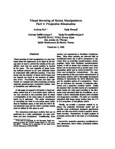
Fig. 1 The fabric lying on the table
The process that is followed in order to sew a piece of fabric with a robotic manipulator can be decomposed in three separate processes-phases described in the following paragraphs. Phase 1: The starting point of the first straight-line section (i.e. the point the needle touches at first) is known in advance. The position-error (r) from the needle and the orientation error (θ) in relation to the sewing line are computed (Fig.1). Next, the designed fuzzy decision system outputs the linear and angular velocity of the fabric. In particular, the position error (r) and the orientation error (θ) and their change with the time are the input data, whereas the linear and angular velocity of the end-effector are the output data. Given the time step ∆t and the orientation angle φ, the new position of the end-effector is computed. The fabric is transferred to a new position as a result of the movement of the end-effector, which is stuck on the fabric so as no slipping between the gripper and the fabric occurs. This process stops when the edge of the fabric reaches the needle with the desired orientation within an acceptable tolerance. Phase 2: The curve is ready to be sewed. At each step of the algorithm, the fabric is sewed along the current straight-line segment. During sewing, the fabric is guided along the sewing line with a constant velocity, which should be the same with the velocity of the sewing machine, so that good seam quality is ensured. Phase 3: The curved side of the fabric has been sewed and the fabric is rotated around the needle until the next side coincides with the sewing line. The
The vision feedback consists of two images by two separate cameras. The first image contains the total area of the workspace, while the second is an image of a greater resolution in the area near the needle. The first image is used for tracking the fabric in the working area, while the second is used for the calculation of the deviation from the desired seam path. This is used as the error feedback to the designed visual servoing system for the path planning by the robot. The novel part in this work in relation to [6] as far as vision is concerned is the determination of a set of points approximating the curved seam path. At first the acquired intensity image of the second camera is automatically thresholded and a binary image is produced. In the next step the boundaries of the image’s main object are extracted in the form of pixel coordinates in clockwise order. The Teh-Chin algorithm [7] has been implemented in order to extract the dominant points of the curve. The algorithm has been slightly modified so as to be applied to open curves and to smooth the noisy contour. The main contribution of [7] is the determination of the Region of Support of the curve without the a priori use of a scaling factor. In fact the scale is determined at every point allowing both fine features and coarse features to be detected. However, the authors have not addressed the case of noisy curves. In this case undesired dominant points may occur detected by the algorithm as fine features. In order to overcome this problem a smoothing factor has been added by simply increasing the step of the algorithm searching for the Region of Support. Normally it is set to 1 pixel, however in our case it is increased to Stp pixels.
Stp = a ⋅ N
(1)
The Stp is defined by Eq.1,where N is the length of the curve in pixels and a is a real number a ∈ (0,1] declaring the percentage of the integral square error (ISE) [8] of the approximation that is included in each
step. The ISE depends on the amount of noise in the curve and is set experimentally, taking into consideration that as noise increases so does a. This way the noise is filtered, but the algorithm can still discriminate multiple higher scales. Moreover another modification of the algorithm has been necessary since only closed curves were considered. According to the algorithm every point lies at the centre of its Region of Support, however the criteria set by Teh-Chin in [7] hold in the case of an asymmetric region, which is the case near the edges of an open curve. Thus the area examined in every step of the algorithm in our case is bounded by the two edges of the curve.
2.3.Robot sewing Robot sewing is a complicated task that demands high accuracy, so that good seam quality is produced. The fact that current robots present limitations in their movement makes the whole process even harder. In the special case where the curve is an arc section, the sewing process is relatively easy, since the robot is programmed to follow part of a circle. However, the up-to-date robots can only be programmed to make straight or circular motions. Therefore, sewing a fabric with arbitrary curvatures is a much more complicated task and can only be performed by approximating the curve with small straight-line movements. The procedure that is followed is described in Section 2.3.2.
2.3.1. Robot sewing arc sections In the special case where the curve is a section of a circle, the sewing process along the arc section is rather easy. Since the points that constitute the arc section are known from the image, the centre of the circle can be easily found by the equation that describes the circle. The centre of the circle can also be found in the robot coordinate system, since the relation between millimetres and pixels is known. It is obvious that sewing arc sections is a position-based procedure. For sake of simplicity, a piece of fabric with one edge that is constituted by a semicircle edge is going to be sewed (Fig.2). Suppose that the needle is at point A, point O is the centre of the circle and point B is the position of the robot end-effector on the fabric. The end-effector B should make a semicircle with centre O and radius OB in order that all points of the semicircle edge pass through point A. This can be done by programming the robot to make a circular movement
of 180° through the internal robot command (MVR) and defining three points in the robot coordinate system: the centre, the starting point B, and the ending point of the end effector.
A
O B
Fig. 2 Fabric with a semicircle edge
It should be mentioned that the pieces of fabrics that constitute real clothing are mainly composed of arbitrary curvatures. Circular or semi-circular seam paths are mainly used for aesthetical or decorative reasons.
2.3.2. Robot sewing arbitrary curves The need for approximating the curved edges through straight lines arises from the fact that current robots can only be programmed to make straight or circular motions. However, sewing a curve with arbitrary curvatures is a complicated task that requires special treatment. Our major goal is to ensure that the deviation from the desired path is lower than a predefined acceptable limit, so that the seam can be considered successful and the seam quality is satisfactory. In our method, the curved edge is approximated by small straight-line sections defined by sequential dominant points. The dominant points are detected by the image analysis, so that the maximum deviation between each line segment and the corresponding curve section is lower than 12 pixels (≈1 mm), as described in Section 2.2. Fig.3 shows the piece of fabric that is going to be sewed and the dominant points detected on the curved edge. Firstly, the dominant points (Α, Β, C, D,…) are extracted from the image. Then, the ‘seam line’, which is inside the outer edge, is found. The fabric is moved from its initial random position so that the first dominant point coincides with the needle-point A΄ (Fig.4). After that, the fabric should be rotated about the needle by the angle ψ, so that the straight-line section A΄B΄ coincides with the sewing line. Since the
respectively. Consequently, the next line-segment to be sewed is defined by the needle-point and the next dominant point. 3. Experimental results
Fig. 3 Image of the fabric at the area near the needle
coordinates of the needle point A΄ and the dominant point B΄ are known in the image-coordinate system, the orientation angle of line section A΄B΄ can easily be computed. The angle ψ is computed as the difference between the sewing line’s orientation angle minus the orientation angle of the line section A΄B΄. sewing line B(xB,yB)
ψ A΄
Fig. 5 Image of the fabric at the area near the needle
D΄
C΄ B΄
A(xA,yA)
D(xD,yD)
C(xC,yC)
The experiments were carried out using a robotic manipulator with 6 rotational degrees of freedom (RV4A) and controlled by a PC AMD Athlon (tm) 64Processor 3000 + 1,81 GHz running under Windows XP. The robot has been programmed in Melfa-Basic language in Cosirop environment, while the analysis of the visual information is performed with Matlab 7.1. The vision system consists of a Pulnix analog video camera at 768×576 pixels resolution RGB
end-effector ψ
Fig. 6 Binary image of the fabric’s boundaries Stp=1, 19 dominant points (black circles)
S
Fig. 4 Robot motion for sewing the fabric
To achieve the rotation of point B΄ around point A΄ by ψ counterclockwise, the end effector should rotate by ψ around point A΄ on the xy-plane. Since point A΄ and the current end-effector’s position are known in the robot coordinate system, the final point of the end-effector is computed. After the robot moves to its new position rotating around the needle, line section AB has obtained the same orientation with the sewing line. The end-effector moves straight with a constant speed (equal to the sewing machines speed) in the direction of the sewing line (expressed by the vector G S ), until point B΄ reaches point A΄. Point B΄ has been definedin the robot coordinate system using the relationship between pixels and millimeters. After that, the whole procedure is iterated, until the last straightline segment is sewed. At this point, it should be mentioned that point B reaches point A with a small deviation resulting from the vision errors and the robot position error, which is within ± 1 pixel (≈0.08 mm) and ± 0.03 mm
Fig. 7 Binary image of the fabric’s boundaries Stp=10, 4 dominant points (black circles)
with focal capabilities ranging from 1m-∞ and an analog video camera of the same resolution using Sony CCD and Samsung zoom lenses. Both cameras are fixed above the working table in a vertical position, so that the fabric is kept in the field of view of the first camera during the servoing and the area near the needle is in the field of view of the second camera. The cameras are connected to Data Translation Mach 3153 frame grabber through coaxial cables. The shape of the fabric consists of two straightline segments and an arbitrary curve, its colour is red and it has large resistance in bending so that its shape remains almost unchangeable and flat without folding or puckering during handling on the table. A pointer fixed at the contact point-position was used instead of an actual sewing machine, because the intent of the demonstrations was the approximation of an arbitrary curve and not the effects associated with the sewing process. At this point certain parameters of the image
feature extraction stage have been set. The image near the needle (Fig.5) has a resolution of 305 dpi, which means that 1 mm in space corresponds to 12 pixels in the image, N has been set to 120 pixels (corresponding to 1cm) and a to 0.0833, so the step has been 10 pixels. In Fig.7 the fabric’s boundaries (white curve) and the detected dominant points by the modified algorithm are illustrated, while the results of the original Teh- Chin algorithm are shown in Fig.6. It is clear by these figures that in our case a smoother, but still accurate, version of the noisy contour is derived.
Acknowledgements
This work is financed by the General Secretariat for Research and Technology of Greek Government as part of the project “XROMA-Handling of non-rigid materials with robots: application in robotic sewing” PENED 01. University of Patras is partner of the EUfunded FP6 Innovative Production Machines and Systems (I*PROMS) Network of Excellence.
5,0 deviation (pixels)
without requirements in special geometrical computations. Fuzzy logic in robot motion control increases the intelligence of robots and enhances the capability of dealing with uncertainty. Considering the future research work, the proposed algorithm can be extended so that it can take into account the distortions presented during handling of fabric by the robot.
4,0 3,0 2,0
References
1,0 0
5
10
15
20
25
curve perimeter
30
35
40
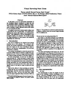
Fig. 8 Deviation between real and desired path
[1] Torgerson E. and Paul F.W. Vision-Guided Robotic Fabric Manipulation for Apparel Manufacturing. IEEE Control Systems Magazine (1988), 15-20.
In order to validate the feasibility of the algorithm, the sewing process is repeated many times. For all tested cases, the algorithm is proved to be quite robust and efficient. The deviation (in pixels) between the real and the desired curve is shown in Fig.8. The maximum deviation is 4,7210 pixels (≈0.39 mm) and is lesser than the maximum acceptable limit of 12 pixels. The average value for the deviation is 2,9172 pixels (≈0.24 mm), which is acceptable.
[2] Kudo M., Nasu Y., Mitobe K. and Borovac B. Multi-arm robot control system for manipulation of flexible materials in sewing operation. Mechatronics 10, (2000), 371-402.
4. Conclusions
[5] Hutchinson S., Hager G.D. and Corke P.I. A tutorial on visual servo control. IEEE Transactions on Robotics and Automation 12(5) (1996), 651-670.
In this paper, a method for sewing fabrics with curved edges is introduced. The curve is approached through small straight motions defined by the dominant points detected by the image analysis and then correcting the path rotating the fabric around the needle. The secondary goal of approaching the curved line within an acceptable limit is satisfied. The experimental results show that the proposed approach is an effective and efficient method for guiding the fabric towards the sewing machine, sewing each one (straight- or curved) edge and rotating it around the needle. The system demonstrates flexibility, since fabric of any shape, size or colour can be sewed
[3] Amin-Nejad, S., Smith J.S. and Lucas J. A visual servoing system for edge trimming of fabric embroideries by laser. Mechatronics 13, (2003), 533-551. [4] Omirou S. A locus tracing algorithm for cutter offsetting in CNC machining, Robotics and Computer–Integrated Manufacturing 20, (2004), 49-55.
[6] Zacharia P., Mariolis I., Aspragathos N. and Dermatas E. Visual servoing of a robotic manipulator based on fuzzy logic control for handling fabric lying on a table. IPROMS Virtual Conference, 4-15 July 2005, 411-416. [7] Teh C.H.and Chin R.T. On the detection of Dominant Points in Digital Curves. Trans. Pattern Analysis and Machine Intelligence 11, (1989), 859-872. [8] Rosin P.L. Techniques for assessing polygonal approximation of curves. IEEE Transactions on Pattern Analysis and Machine Intelligence 19, (1997), 659–666.