Mälardalen Real-Time Research Centre, Department of Computer ... VCE develops computer control .... specification, the programmer also has the execution.
Experiences from Introducing State-of-the-art Real-Time Techniques in the Automotive Industry Christer Norström, Mikael Gustafsson*, Kristian Sandström, Jukka Mäki-Turja and Nils-Erik Bånkestad** Mälardalen Real-Time Research Centre, Department of Computer Engineering Mälardalen University, Västerås, Sweden *TietoEnator ArosTech AB, Västerås, Sweden ** Volvo Construction Equipment Components AB, Eskilstuna, Sweden www.mrtc.mdh.se
Abstract The use of state-of-the-art real-time techniques in industry remains infrequent. The reason for this, we believe, is three-fold: (1) the lack of commercially available tools, (2) the lack of methodologies based on real-time theory throughout the complete development process, and (3) the lack of competence in real-time theory among industrial practitioners. In this paper we present a case study of the introduction of state-of-the-art real-time techniques in industry. The case study was performed as a collaboration between Mälardalen University and the industrial partners Volvo Construction Equipment Components AB (VCE) and TietoEnator ArosTech AB. VCE develops computer control systems for construction equipment vehicles, such as wheel loaders, graders, and articulated haulers. TietoEnator ArosTech is a firm of consultants with recognized competence in the field of embedded real-time systems. The contribution of this paper consists of the findings from the introduction of a method and real-time techniques into an industrial project. The main result reported can be summarized as “people, not papers, transfer technology”.
1
Introduction
Development of complex embedded systems is an expanding field, i.e., more and more applications are being based on the use of embedded computers. Examples include highly complex systems such as medical control equipment, mobile phones, and vehicle control systems. Most of such embedded systems can also be characterized as real-time systems. “Real-time systems are defined as those systems in which the correctness of the system depends not only on the logical result of the computation, but also on the time when the results are produced” [Sta88]. The increased complexity of these systems leads to increasing demands with respect to requirements
engineering, high level design, early error detection, productivity, integration, verification, and maintenance. This calls for methods, models, and tools which permit a controlled and structured working procedure during the complete life cycle of the system [Kal88]. Many methods such as UML-RT and HRT-HOOD are available for designing real-time systems. These methods, however, tend to concentrate on logical and structural decomposition, providing limited support for expressing and analyzing the temporal behavior of the system. Furthermore, the tools currently available provide limited support for automatic mapping from the design to a resource structure, especially with respect to temporal attributes. This often leads to discrepancy between the design and the implementation, and consequently the system will be difficult to maintain. As an alternative we have developed a model and method focused on the real-time properties of a system. The objective of the model and method is to support the development of a high level design, including specification of properties such as temporal constraints, communication and synchronization. Furthermore, the model and method support formal verification of these properties, and early system integration, and permit regression testing. The aim of this paper is to present our findings from the introduction of this model and method in an industrial project, performed as a cooperation between Mälardalen University, Volvo Construction Equipment AB (VCE), and TietoEnator ArosTech AB in Sweden. The validity of these findings is based on a single but extensive case study of one industrial project. Some of our findings are confirmed by similar results from other industrial projects utilizing stateof-the-art real-time techniques [Cas98, Mel98]. VCE has used onboard electronics in their products since 1981 for specific functionality. More and more functionality can be provided by the computer control system and this has led to an increasing number of people being involved in the
development of each product, and thus a need for uniform development methods and tools. This was the motivation for the co-operation. Since a new architecture was to be developed, we were given the opportunity to introduce new techniques and methods. The outline of the paper is as follows: Section 2 briefly presents the application characteristics. The development method and model are presented in Section 3. In Section 4 we present our findings, categorized into findings related to methodological aspects, technology transfer, and technical issues. Finally, Section 5 contains certain of our conclusions.
2
Application characteristics
The application concerned is a vehicle control system with high demands on safety, reliability, and accurate timing. The system hardware consists of two nodes connected via redundant buses. The application consists of 80 tasks, running with different periods, which collaborate to perform certain control functions. These tasks have hard real-time requirements, are scheduled off-line and execute according to a dispatch table on-line. Each node is very I/O intensive, the complete system incorporating 150 I/O channels. The execution times of the tasks in the application range from 10 µs to 1 millisecond. The application is interrupt intensive, due to the construction of the hardware and the effect of these interrupts cannot be neglected when scheduling the hard real-time tasks. The hardware could not be modified as it had been designed and certified before development of the software was begun. The worst case utilization of the processors, for the critical part, is approximately 80%, divided into 35% for interrupts and 45% for hard real-time tasks. The remaining spare capacity is used by on-line scheduled soft real-time tasks. During run-time, the spare capacity will exceed the remaining 20% if the load generated by hard tasks and interrupts is less than the worst case.
3
Development method and model
In this section we will present the method and the model used in developing the application. The development method defines the workflow when developing an application. The method employed in this project is iterative and quite traditional. The emphasis in the method is to derive a high level design which enables early analysis of timing, communication, and synchronization properties. To facilitate this it is necessary for synchronization, communication, and temporal attributes to be defined early in the design process and for this we need a suitable design language to describe the model of the application.
The objective of this model is two-fold. First, the model should enable easy representation of the application and its requirements. Second, the model should be described using a language which enables formal analysis and automatic code generation (in our case analysis of timing, communication, and synchronization properties). There is, however, a tradeoff between these two objectives. Analysis and automatic code generation, from a formal and precise design description, is often straightforward. However, such descriptions tend to be difficult to write and difficult for industrial practitioners to understand. On the other hand, a specification in, for example, plain language is easy to understand but difficult to analyze. We have tried to balance these two objectives when designing the language. We will describe the method for developing an application as illustrated in Figure 1. In each step we briefly introduce the model and its language elements. I.
Requirements engineering. The customer ordering the system specifies the requirements. II. Requirements analysis. In this stage the high level functions of the application are identified from the requirements specification. It is also important here to determine temporal constraints for these functions. III. High-level system decomposition. In this stage the different operational modes of the application are identified together with valid transitions between them. A mode describes specific functionality in a system state. If the functionality differs substantially from one state to another, these should be separated into different modes. An example is the control system in a vehicle, which can have different functionality depending on the status of the vehicle, such as operating, reduced, failed, and init. IV. Function decomposition and structuring. The functions, for each mode, are decomposed into transactions. Transactions in turn are decomposed into smaller units called tasks. Tasks are defined by their low-level functions together with the data flow between them. Each task is provided with a set of typed in-ports and out-ports. The execution semantics of a task are: to read its in-ports on activation, then to perform the function and, before termination, to write the result to its out-ports. This construction implies that each task can be designed without knowledge of where input data was produced, or where the output data produced will be used.
Requirements engineering I
Requirements analysis II
High level system decomposition III
Function decomposition and structuring IV Design Mapping temporal constraints to attributes of the task model V
Definition of execution time budgets VI
Feasibility check and automatic implementation VII
Implementation and module testing VIII
System integration and verification IX
Figure 1: The design method Example 1: A multirate controller. The transaction consists of two sampling tasks, S1 and S2, a controller task C, and an actuator task A. The data-flow of the transaction can be seen in Figure 2. ❏ S1
C
A
S2
Figure 2: Data-flow between tasks. Functionality having high responsiveness requirements or which occurs frequently but with short execution times cannot be implemented as a periodic
task as the overhead would be too high. Such low-level functions are therefore implemented as interrupts. V. Mapping temporal constraints to attributes of the task model. In the previous stage high level functions were decomposed into tasks and structured according to the interaction between them. In this step we break down the high level temporal requirements into temporal attributes for tasks and the synchronization between them. Synchronization can be defined by precedence relationships between tasks or by mutual exclusion of tasks sharing a common resource. The temporal attributes are period, the Worst Case Execution Time (WCET), the release time, and the deadline of a task. The WCET is the estimated execution time for the task. The release time is the earliest time at which the task can be activated, relative to its period start. The deadline is the latest time at which a task is permitted to terminate, relative to its period start. Further, the temporal behavior for each interrupt is defined by an inter-arrival time and an execution time. Example 1 (continued): The temporal attributes, derived by the control engineer for the multiratetransaction example are as follows (note that we have no knowledge of the execution times of the tasks as yet, hence the question marks): • Tasks S1 and S2 have period, release time, deadline, worst case execution time in µs = (1000, 0, 1000, ?). • Task C = (5000, 4000, 5000, ?). • Task A = (5000, 4000, 5000, ?). To enforce order between the controller and actuator task, we specify a precedence relation between C and A, i.e., task C precedes task A. ❏ VI. Defining Execution Time Budget. Traditionally WCET is obtained by either measurement or by statically analyzing the code produced for each task. In this approach, however, execution time budgets are estimated, being used later in step VIII as implementation requirements. The reason for this is that a feasibility test for the system, and a possible reengineering, can then be performed at an early stage, thus permitting early detection of design errors related to resource utilization, communication and synchronization. Example 1 (continued): The question marks are replaced by estimated time budgets. Since this is a delicate issue, it requires highly skilled engineers with long experience. ❏ VII. Feasibility check and automatic implementation. The formally described design can be checked for temporal correctness, with a tool designated Configuration Compiler (CC), even if no actual (low-
level) implementation has been produced. The CC maps the design description to a resource structure. The CC is a pre-run-time scheduler which generates dispatch tables for running the tasks and the communication infrastructure for each mode. This constitutes an application skeleton for the running and communication of the tasks. In addition to the mapping of the model, CC also supports specification of architecture-specific attributes such as HWperformance, resolution of the run-time dispatcher, communication times, and the number of nested preemptions permitted. The implementation of the CC is based on a heuristic tree search strategy, similar to the one presented in [Ram90]. The major difference is that this scheduler takes into account interrupts [San98] and architecture-specific attributes. The current version of CC is adapted to the real-time operating system Rubus (both commercial products, see www.arcticus.se). VIII. Implementation and module testing. The tasks are simply implemented by traditional programming (coding). In addition to the traditional functional specification, the programmer also has the execution time budget as an implementation requirement, i.e., the programmer must implement the specified function without exceeding the budget. The module testing includes both verification of functional behavior and checks that time budgets are not exceeded. If a time budget cannot be met, a redesign is required. IX. System integration and verification. The integration phase is usually performed quickly and without problems since the actual integration was performed during the design phase. The major task is the integration testing.
4
Findings
In this section we will describe our findings from the introduction of the method and model. The findings are categorized as those related to development method, technology transfer, and technical issues respectively. The development method covers the findings based on the use of the design language and method. The technology transfer section describes issues regarding the transfer and introduction of new techniques and especially real-time techniques into an organization. The technical issue section presents new or relevant technical challenges encountered during this work.
4.1
Development method
Finding 1: The design language (1) provides the means for concurrent implementation and (2) facilitates efficient integration of new personnel into the project.
Motivation: (1) The task model stipulates tasks, which have no synchronisation or communication within the code. Observe that each task uses a computational model based on input calculation - output. As a result each task can be implemented and tested in parallel since each task is only dependent on its own state and the values at its in-ports to make a calculation. Module testing is thus very simple, values are fed to the in-ports and out-ports are monitored. This model facilitates regression testing of modules in a straightforward way. (2) A small group of people with knowledge of the system and a feeling for future demands on the system develops the design. The design they produce must be stable, that is, major changes required after the implementation phase are to be few. It is then easy to introduce new personnel into the implementation phase since each new employee or consultant need only to understand the design language and follow the specified interface to be able to begin to implement and test. The introduction of the design language has decreased the introduction time for new employees and consultants substantially. Finding 2: The design language provides sufficient details for analysis and code generation. Motivation: Using the design language provides three major benefits: •
It gives the application skeleton, which can be analyzed without needing a single line of code. • The analysis leads to early detection of errors in communication, synchronization, and timing. • Simplified system integration. Currently, we can analyze communication, synchronization, and timing requirements. Three different aspects of communication are analyzed. Firstly, the types of connected ports are checked to ensure that the proper data types are passed to the tasks. Secondly, the analysis will reject a design in which the amount and rate of data passing through the system makes it impossible to fulfill the temporal requirements. Thirdly, data consistency is checked. In this case also, if there is no way of fulfilling all timing requirements with guaranteed data consistency, the design is rejected. The analysis of the synchronization ensures that all precedence and mutual exclusion relationships between tasks can be guaranteed in conjunction with guaranteed timing requirements. Finally the analysis of the timing requirements reveals if a schedule for the given design and execution time budgets which fulfills these timing requirements is possible. If it is impossible to fulfill the timing requirements the design will again be rejected. The analysis presented above leads to early detection of design errors of the properties analyzed. Such errors are
otherwise often found in the integration phase of the project and then cost time and effort to correct. System integration is also simplified by the early analysis. If the implementation for each task complies with the interface given by the design, i.e., retrieving data only from the in-ports, performing the desired function within the given execution time budget, and producing data only to the out-ports, the integrated system will fulfil the design and thus satisfy the requirements. Thus, one step in the development process, which is often quite troublesome and leads to costly delays, is greatly simplified. Note that all that need be added to implement the design is the task code, everything else is generated automatically. Finding 3:Use of the method increases the time spent in the design phase but shortens the implementation time. Motivation: The time to complete the design has increased in comparison with similar projects in which traditional informal techniques (such as structured analysis and design) have been used. This is not surprising since the development of a formal and detailed design requires more effort, compared with a design written in plain language only. However, the precise design has resulted in shorter time being spent in implementation, testing, and integration due to reasons described earlier. Aware of the difficulty of providing formal evidence for this claim, we remain confident that it is valid. Further, we believe that the time spent in implementation and testing will be reduced even more in future projects, when engineers become more familiar with the new approach. We also believe that it will be much easier to maintain a system based on a precise design as compared with a traditional system. This is mainly due to two factors: 1. Normally, the implementation and the design tend to diverge which makes it difficult to foresee the impact of changes or added functionality. One way to avoid this divergence is to use tools which enforce consistency by automatically, producing verified functionality from the design description. 2. Even if there is a close match between the design documents and the implementation it is not easy to foresee the impact of changes or added functionality. Performing the changes in a consistent and formal design, several properties can be analyzed. Thus changes or add-ons which do not comply with the functionality already implemented will be detected at an early stage. Finding 4: Using execution time budgets to facilitate early schedulability analysis proved to be a feasible approach. Motivation: To be able to make an early capacity analysis of system resources such as processors and buses, each task must have
an execution time budget. This budget states the amount of the processor capacity the task is permitted to utilize. Specifying this budget, i.e., relating functional requirements to the execution time of a task, can sometimes be difficult. In this project we were surprised that the budget estimations were so accurate. The reason for this, we believe, was that the engineers who specified these budgets had many years of experience in control system design and hardware-close programming. To verify that the implementation fulfils the requirements, the execution time for each task was measured and, in some cases calculated.
4.2
Technology transfer
Finding 5: Tools, education (courses, tutorials), carriers, and adapters are required to facilitate a successful transfer of real-time technology to industry. Motivation: Tools: When transferring a theory to industry, unless very simple [Bat99], it is necessary that the theory be encapsulated in a tool, demonstrating its practical use [Sch96]. A good example of a tool, which encapsulates advanced technology, is the traditional compiler. The first version of the tool, CC, was written in a high level language which was easy to adapt to new requirements. The handling of these up-coming requirements in an efficient way is important for success in the transfer, an operation in which the carrier, described below, plays a significant role. CC was later ported to a lowlevel language resulting in an efficient implementation. Courses: We learned that an engineer requires at least two days of training to understand sufficient basic real-time theory and associated methods to be able to work in the design of new systems. In reality it will take an experienced engineer about a week including the training course to be productive, when using the model and methodology. Carrier: The success of this project has been mainly due to one member of the research group beginning to work as a consultant for TietoEnator ArosTech at VCE. Regardless of how many excellent reports are written, people are needed to carry the results [Dal94]. A related example is the development of the control system for Volvo S80 for which Ken Tindell and others carried the response time analysis for the CAN bus into a tool and implanted that tool in the Volvo Car Cooperation organization [Cas98, Mel98]. Citation: "Tech transfer is a contact sport. People, not papers, transfer technology" [Fol96]. Adapters: Even if we have carriers we need early adapters at the company to take the technology into the company and its
organization. These people need to be authoritative to be able to sell the new technology in the organization. There is always a healthy conservatism in all organizations. Therefore one must find people ready to invest enough time and energy to determine if or not the technology is applicable and gives an added value to the development of their products [Ben96]. Finding 6: The major problem when introducing real-time techniques in an organization is to change the requirements elicitation process to include temporal requirements. Motivation: Several independent sources confirm this finding (Volvo Car and Volvo Construction Equipment). All the engineering disciplines within a company must change their way of specifying electronics requirements at the same time. The main problem is that when a timing requirement for a high-level function has been accepted, it is not easy to reconsider it. Timing requirements become more firmly established the longer the timing constraint remains in force. This becomes apparent when a new function is added, resulting in a negative schedulability test. To add such a function, either execution time budgets that are too generous or timing requirements that are too strict need to be reconsidered. Assuming that the overestimation of execution times is negligible, the temporal requirements must be reconsidered. To be able to determine which temporal requirement to relax, there must exist a notion of confidence in the timing requirements. As an example, consider, in an application, the time until a lamp illuminates after operating the lamp switch. Assume that as a requirement, this time is specified as 200 ms. If it is subsequently found that the system cannot be scheduled, it must be decided which requirements can be relaxed to provide a feasible schedule. If confidence in the time specified, 200 ms, is low, relaxing of this requirement could be considered. The results from the requirements elicitation process must therefore be clearly expressed and well motivated since they will be used during the complete life cycle of the system.
4.3
Technical issues
Finding 7: The task model used (described in Section 2) is in some cases too restricted when handling control jitter for simple controllers and especially for multirate controllers. Motivation The limited expressiveness in the task model is related to the jitter problem and the multirate communication problem. Specifying release times and deadlines for the tasks involved in the computation can be used to satisfy, for example, jitter requirements. However, this is a problem since the engineer ends up with the burden of distributing the release times and deadlines to avoid overloading a specific time-window. This means that the engineer must act as a pre-scheduler, an inefficient procedure. The possibility
of specifying relative timing constraints would be a preferable property of the task model. For example, a sampling task is required to run with a certain period with a specified tolerance (Period ± tolerance). Relative timing constraints could also be used for specifying latency constraints, e.g., the time between sampling and actuation. Furthermore, when a controller consists of several entities which run with different periods, i.e., multirate control, the possibility of specifying latency constraints would be desirable. A task model supporting this would simplify the specification of a system. Extending the task model is an easy task but developing automated tools scheduling such a system is not an easy task. Finding 8: Task model and scheduling techniques reported in literature must be extended to take real-world requirements into consideration. Motivation: In developing the scheduling tool, CC, for this task model, we had to take several important aspects into account to obtain efficient use of the target system. The two aspects we will cover here are schedule representation and the taking of interrupt overhead into account. Schedule representation. A common representation of a static schedule is a vector, one position in the vector representing a discrete point in time at which the execution of a task can begin. The resolution of time is determined by the frequency of the periodic clock which drives the taskdispatcher. If the execution time of a task is less than this resolution, or if it exceeds a multiple of the resolution by a small fraction, the utilization of the CPU resource will decrease. This is because there will be time intervals which cannot be used to execute tasks. An apparent solution to this is to increase the frequency of the periodic clock. However, with a higher clock frequency, the dispatcher will use more of the CPU resources, since it will execute more often. Another way of representing a schedule is as a list of rows, where each row represents a point in time at which the dispatcher is to start the execution of a sequence of one or more tasks. The first task in this sequence, or chain, is started at the given point in time. All other tasks in the chain are started as soon as the preceding task in the sequence has completed its execution, without the need for the clock to trigger the dispatcher. This representation will allow several tasks to be executed during an interval less than the period of the dispatcher clock. Hence, the dispatcher overhead can be kept low while the utilization of the CPU resources remains high. Interrupt overhead. Typically, pre-run-time schedulers do not take interrupts into account, assuming that their execution times can be ignored or incorporated into task execution. In many applications, the interrupts are, however, not negligible and their inclusion in task execution times is too conservative and inefficient, as in this case.
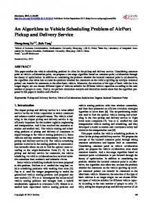
Furthermore, as inter-arrival and execution times of interrupts are shorter than the resolution of the online dispatcher and the arrival times are unknown, interrupthandling routines cannot be modeled as pre-scheduled tasks. Consequently we had to develop a method for handling interrupts in an efficient manner. The method developed combines a tree search algorithm with response time analysis, see the paper by Sandström et al [San98]. Finding 9: To make a pre-run-time scheduler tool really useful, the user must be provided with feedback when the system is not schedulable. Motivation When applying scheduling in industrial projects, engineers are faced with a problem which has only to a very limited degree been addressed by the real-time research community, namely how to provide the user with constructive feedback when a feasible schedule cannot be found. Specification file
Schedules
Pre run-time scheduler unfeasible system
Confused designer
feasible system
Happy designer
NULL
Figure 3: Pre-run-time scheduling: present situation This limited feedback problem leads to confused designers, as illustrated in Figure 3, who more or less at random must optimize and modify the specification. However, to help the designer to provide a specification for which the pre-run-time scheduler can find a feasible schedule, there is a need for heuristics which analyze the specification for semantic problems and return constructive feedback to the user. That is, the user should be provided with suggested means of solving the problem, i.e., how to modify the specification to enable the generation of a feasible schedule. We have developed a method for providing feedback to the user by calculating a load function for the system. By identifying bottlenecks in the system specification we can guide the designer in modifying the input to the pre-run-time scheduler. The underlying hypothesis is that there is a correlation between the points in time when the load function has a high value, and the locality of the bottlenecks in the specification which lead to an non-feasible schedule [All96]. Finding 10: Incremental scheduling is needed to minimize the verification effort when only minor updates have been performed on the application. Motivation
When an application has been tested and used successfully in a vehicle for some time, the application is accepted and released. If some new functionality is subsequently added, as much as possible of the execution sequence in the application should be retained to avoid major re-verification efforts. This is not possible today, because the addition of new functionality to the application requires the generation of a completely new schedule. The major drawback of this approach is that the application verification and validation must be repeated to guarantee the functionality. A desirable feature of a scheduler would be the possibility of adding new tasks incrementally to the application without affecting the sequence and timing of the tasks already scheduled to minimize the re-verification effort. A scheduler which accepts both the updated design specification and the previously verified schedule as input could solve this problem. The scheduler could try to find space in the old schedule for the new tasks or otherwise to minimize the number of changes necessary. We believe that it is more important to retain the sequence than the exact start times of tasks if the timing requirements are fulfilled. We believe this because there are often margins in execution windows for tasks while a change of sequence could have severe impact on, for example multirate transactions, which are often sensitive to data age.
5
Conclusion and Future research
In the real-time community, which scheduling strategy should be used is often debated [Xu00]. For embedded systems there appear to be two schools of thought: the prerun-time scheduling school and the Fixed Priority Scheduling (FPS) school. Our experience indicates that we could have used FPS instead of pre-run-time scheduling since the scheduling strategy is only a small part of the development of a system, see Figure 1. The important factors are the possibilities of specifying the system on a high level, of facilitate automated analysis and of automatic mapping to a resource structure. We believe that the project presented has been successful in transferring real-time techniques from a university research laboratory to an industrial partner. As a result, the industrial partner has adopted a more systematic and formalized design process which has shortened the overall development cycle in comparison with similar previous projects while achieving the product quality specified. The use of a formal design language permits early analysis and error detection. Further, the language used has made it possible to generate code automatically. The language has also forced the development team to produce a complete and verified design which is consistent with the implementation. The language does not only simplify the
design but also simplifies the maintenance of the application. Technology has been transferred in both directions, industry providing relevant new challenges for academia such as the interrupt and limited feedback problems. To implement research results they must be encapsulated in tools and extended to handle real-world requirements. Further, there must be early adapters and carriers of the technology. Let us conclude the paper with the observation “tech transfer is a contact sport, people, not papers, transfer technology”! Acknowledgements: We would like to thank Jack Stankovic, Hans Hansson, Sasikumar Punnekat, and Ivica Crnkovic for valuable discussions and for reviewing earlier versions of this paper. We would also like to thank Krithi Ramamritham for encouraging us to write this paper. Finally we would like to thank the anonymous reviewers for constructive feedback. Mälardalen Real-Time research Centre (MRTC; www.mrtc.mdh.se) is a research centre in Västerås, Sweden, supported by Swedish industry, the Swedish Foundation for Knowledge and Competence Development (KK-stiftelsen) and Mälardalen University.
6
References
[Ben96] J. L. Bennett. Building Relationships for Technology Transfer. Communications of the ACM, Volume 39 Number 9. Sep. 1996. [All96] B. Allwin, K. Sandström, and C. Eriksson. Constructive Feedback Turn Failure into Sucess for Pre-Run_time Schduled Systems. 11th Euromicro Workshop on realtime systems. [San98] K Sandström, C. Eriksson, and G. Fohler. Handling Interrupts with Static Scheduling in an Automotive Vehicle Control System. In Proceedings of the fifth International Conferance on Real-Time Computing Systems and Applications, pp. 158-165, October 1998. ISBN 0-8186-9209-X. [Eri96] Christer Eriksson, Jukka Mäki-Turja, Kjell Post, Mikael Gustafsson, Jan Gustafsson, Kristian Sandström and Ellus Brorson. An Overview of RTT: A Design Framework for Real-Time Systems. Journal of Parallel and Distributed Computing August 1996. [Fol96] Jim Foley. Technology Transfer from University to Industry. Communications of the ACM, Volume 39 Number 9. Sep. 1996. [Cas98] L. Casparsson, A. Rajnak, K. Tindell, and P. Malmberg Volcano a revolution in on-board communications. Volvo Technology Report. 98-12-10. [Mel98] K. Melin. Volvo S80: Electrical system of the future Volvo Technology Report. 98-12-11. [Kal88] D. Kalinsky and J. Ready. Distinctions between requirements specification and design of real-time systems. Conference proceedings on TRI-Ada '88 , 1988, Pages 426 – 432.
[Dal94] M Dalziel. Effective university-industry technology transfer. Canadian Conference on Electrical and Computer Engineering, 1994 , Conference Proceedings, Page(s): 743-746 vol.2 [Bat99] I Bate and A. Burns. An Approach to Task Attribute Assignment for Uniprocessor Systems. Proceedings of the 11th Euromicro Conference on Resal-Time Systems, York, England, UK, June, 1999 [Sch96] J. Scholtz. Technology Transfer through Prototypes. Communications of the ACM, Volume 39 Number 9. Sep. 1996. [Ram90] K. Ramamritham. Allocation and Scheduling of Complex Periodic Tasks. In 10th Int. Conf. on Distributed Computing Systems, pages 108-115, 1990. [Sta88] J.A Stankovic Misconceptions about real-time computing: a serious problem for next-generation systems. Computer , Volume: 21 Issue: 10 , Oct. 1988. [Xu00] J. Xu and D. L. Parnas. Priority scheduling versus prerun-time scheduling. Real-Time Systems Journal, 18(1), January 2000.