Jun 21, 1998 - 12 hour Molniya orbit with an apogee of approximately. 39,000 km, mean total ..... m/s for velocity, 1x10⁶ meters for clock bias (3.3 milliseconds) ...
Hardware in-the-Loop Demonstration of Real-Time Orbit Determination in High Earth Orbits Michael Moreau, Bo Naasz, Jesse Leitner, J. Russell Carpenter, NASA Goddard Space Flight Center Dave Gaylor, Emergent Space Technologies
BIOGRAPHY Michael Moreau is an Aerospace Engineer in the Flight Dynamics Analysis Branch at NASA’s Goddard Space Flight Center (GSFC). His research is focused on applications of the Global Positioning System to enable autonomous navigation and formation flying of spacecraft, and the design of GPS receivers for use in space. He received his Ph.D. in Aerospace Engineering from the University of Colorado. Dr. Moreau has been an active participant in both national and regional activities of the Institute of Navigation since 1997, and currently serves as Space Representative on the ION Council. Bo Naasz is an Aerospace Engineer in the Flight Dynamics Analysis Branch at NASA GSFC. His research is focused on development and testing of onboard navigation and control for spacecraft formation flying and autonomous rendezvous and docking missions. He holds a M.S. in Aerospace Engineering from Virginia Tech. Jesse Leitner is a Guidance, Navigation, and Control systems engineer and serves as the lead engineer for Distributed Space Systems at NASA GSFC, responsible for the end-to-end technology program to support multispacecraft missions for NASA. He is the lead analyst for formation flying technology and systems engineering work, serving as the interface between the science and engineering communities in support of a number of upcoming planned and proposed missions. He holds a PhD in Aerospace Engineering from Georgia Tech in the area of nonlinear control systems. He is an Associate Editor for the AIAA Journal of Guidance, Control, and Dynamics and he is an Associate Fellow of the AIAA. David Gaylor is the Director of Guidance, Navigation and Control for Emergent Space Technologies, Inc. He received his Ph.D. in Aerospace Engineering from the University of Texas at Austin. He currently supports the Formation Flying Test Bed at NASA Goddard Space Flight Center developing software and models.
Russell Carpenter is an Aerospace Engineer at NASA GSFC, where he has worked in the Guidance, Navigation, and Control area since 1998. His current research areas involve formation flying GN&C and GPS development, analysis, simulation, and test. Before coming to NASA Goddard, Russell was at NASA Johnson Space Center from 1987-1998, where his research involved development, analysis, simulation, and test of space flight navigation techniques, future exploration missions, and advanced technology experiments. He has been a Principal Investigator or Co-Principal Investigator on numerous technology projects concerning autonomous onboard satellite navigation and autonomous control of satellite formations, re-entry, and attitude determination, and has over 30 publications. Russell attended The University of Texas at Austin, receiving his Ph.D. in Aerospace Engineering in 1996.
ABSTRACT This paper presents results from a study conducted at Goddard Space Flight Center (GSFC) to assess the realtime orbit determination accuracy of GPS-based navigation in a number of different high Earth orbital regimes. Measurements collected from a GPS receiver (connected to a GPS radio frequency (RF) signal simulator) were processed in a navigation filter in realtime, and resulting errors in the estimated states were assessed. For the most challenging orbit simulated, a 12 hour Molniya orbit with an apogee of approximately 39,000 km, mean total position and velocity errors were approximately 7 meters and 3 mm/s respectively. The study also makes direct comparisons between the results from the above hardware in-the-loop tests and results obtained by processing GPS measurements generated from software simulations. Care was taken to use the same models and assumptions in the generation of both the real-time and software simulated measurements, in order that the real-time data could be used to help validate the assumptions and models used in the software simulations.
Presented at the ION National Technical Meeting, San Diego, CA, January 24-26, 2005.
The study makes use of the unique capabilities of the Formation Flying Test Bed at GSFC, which provides a capability to interface with different GPS receivers and to produce real-time, filtered orbit solutions even when less than four satellites are visible. The result is a powerful tool for assessing onboard navigation performance in a wide range of orbital regimes, and a test-bed for developing software and procedures for use in real spacecraft applications.
INTRODUCTION This paper presents results from a study conducted at Goddard Space Flight Center (GSFC) to assess the realtime orbit determination accuracy of GPS-based navigation in a number of different high Earth orbital regimes. Measurements collected from a GPS receiver (connected to a GPS radio frequency (RF) signal simulator) were processed in a navigation filter in realtime, and resulting errors in the estimated states were assessed. The study also makes direct comparisons between the results from the above hardware in-the-loop tests and results obtained by processing GPS measurements generated from software simulations. This provides a means to further validate the clock models, measurement noise parameters, and other error settings used in software simulations of orbit determination performance conducted at GSFC. High Earth orbits in the context of this paper are considered to be any orbit with apogee higher than 3000 km altitude, above which conventional space-capable GPS receivers may not be able to produce an instantaneous position and velocity solution. There has long been interest in expanding the use of GPS beyond low Earth orbit (LEO). Previous work at GSFC has included extensive software simulations to assess absolute and relative navigation performance in different orbital regimes [1], development of new GPS receiver technology for application to high altitude orbits [2], flight experiments [3], as well as development of the capability to conduct realistic hardware in-the-loop tests of GPS receiver performance in high Earth orbits using a GPS RF simulator [4]. This study utilizes GSFC’s Formation Flying Test Bed (FFTB) which integrates GPS receivers, NASA’s GPSEnhanced Onboard Navigation System (GEONS) extended Kalman filter software, and telemetry and commanding interfaces in a manner very similar to how these systems would be integrated on a spacecraft flight computer. The FFTB provides a capability to interface with different GPS receivers and to produce real-time, filtered orbit solutions even when less than four satellites are visible, and the measurements and output data may be optionally logged for post-processing. The system incorporates actual receiver clock and measurement errors, as well as realistic timing and data latencies that would be present on an actual spacecraft. Thus the test setup provides a very realistic assessment of the onboard
navigation performance that may be achieved in these orbits. Throughout the remainder of the paper, the expressions “real-time measurements” or “real-time results” refer to data collected from the GPS receiver during hardware inthe-loop tests and processed in real-time. “Software simulated measurements” or “software simulated results” refer to data generated from software simulations. The next section provides an overview of GSFC’s FFTB, components of which were used to perform the hardware in-the-loop tests. Next the technical approach and specific simulation parameters used for both the hardware and software simulations are outlined. Position, velocity, and clock solution accuracies are presented for the most interesting cases tested, including comparisons to simulated results. Finally some general observations from the study are presented.
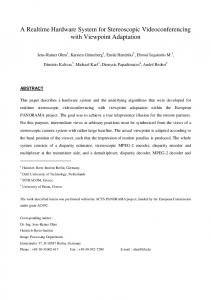
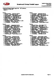
FORMATION FLYING TEST BED The FFTB at GSFC is a unique facility in which high fidelity spacecraft simulation and modeling software and hardware in-the-loop test capabilities are integrated for test and evaluation of spacecraft navigation (absolute and relative) and formation control technologies. The FFTB uses real-time, distributed software to integrate RF signal simulators, actual GPS receivers and cross-link transceivers, and flight processors to provide a real-time simulation environment for system- and component-level studies. The system can be run with one to four spacecraft, with and without hardware in the loop, thus enabling a variety of distributed navigation and communication architectures to be evaluated. In a typical formation flying simulation scenario, multiple GPS receivers are stimulated by a GPS signal simulator to produce pseudorange, Doppler, and carrier phase measurements, which are collected and exchanged by the flight processors and subsequently processed in an extended Kalman filter to generate relative and/or absolute state estimates. These state estimates are then fed into control algorithms, which are used to generate maneuvers required to maintain the formation. In this manner, the flight processor also serves as a test platform for candidate formation control algorithms. Such maneuvers are fed back through the real-time simulation controller and applied to the modeled truth trajectories to close the simulation loop. Figure 1 is a functional block diagram of the FFTB, highlighting the specific components utilized in the high altitude orbit determination study. The key components consist of an environment simulator for generating user spacecraft truth trajectories, a GPS RF signal simulator, a GPS receiver, a flight computer running the GPS receiver adapter software and GEONS navigation filter, custom middleware to handle messaging between FFTB components, and data logger software. A photograph of the actual laboratory setup is shown in Figure 2.
Presented at the ION National Technical Meeting, San Diego, CA, January 24-26, 2005.
2
RS-232
RF
Spirent STR4760
GPS Receiver
Flight Computer
Ethernet GPIB
Ethernet
Spirent Interface Computer
Environment Computer Figure 1– Functional block diagram of Formation Flying Test Bed setup used for the high altitude orbit determination study.
Flight Computers (GEONS)
receiver for this study in order for the navigation filter to have observability of the receiver clock states.
GPS Receivers Trajectory Generation GPS Simulator
Figure 2 – Formation Flying Test Bed real-time orbit determination test setup. The primary GPS receiver used in this study is the Goddard-developed PiVoT GPS receiver. PiVoT is a single frequency (L1 C/A signal) receiver that uses a Compact-PCI architecture and provides 24 correlator channels with four RF inputs. The PiVoT clock is a high quality, temperature-compensated crystal oscillator with a specified Allan variance better than 0.4x10⁻¹⁰ over 1 second. PiVoT also incorporates some basic software modifications that enable it to reliably track and acquire GPS signals in high altitude orbits. The effective tracking threshold of approximately 35 d B-Hz is equivalent to conventional space receivers (i.e., no extended correlation intervals or deeply integrated tracking loop designs were implemented for this study). A simple frequency locked loop is implemented for carrier tracking to provide reliable signal tracking of weaker signals in exchange for reduced measurement noise performance. As will be discussed in more detail later, the ability to recover raw measurement outputs (uncorrected for receiver clock bias and drift) was another critical capability of the PiVoT
GEONS is a flight software package developed by NASA to provide onboard orbit determination in any orbit. GEONS is capable of using GPS data, one-way forwardlink Doppler data from ground stations and TDRSS, optical measurements from attitude sensors, and intersatellite crosslink data to simultaneously estimate absolute and relative orbital states for satellites and satellite clusters. GEONS employs an extended Kalman filter (EKF) augmented with physically representative models for gravity, atmospheric drag, solar radiation pressure, clock bias and drift to provide accurate state estimation and a realistic state error covariance. GEONS' high-fidelity state dynamics model reduces sensitivity to measurement errors and provides high-accuracy velocity estimates, permitting accurate state prediction during measurement outages or degraded coverage. The FFTB uses a SPIRENT Model STR 4760 GPS simulator running SimGEN for Windows version V2.41. The RF signal simulator receives user spacecraft state information as an input and generates GPS RF signals subject to user specified simulation parameters. The user trajectory is generated by an external environment simulator using an initial state vector propagated using high fidelity dynamics and force models. This trajectory may be provided to the RF signal simulator via a real-time interface, or using a pre-generated input command file. The latter option was used in this study. The FFTB setup provides some critical capabilities for this study. The RF signal simulator, properly configured, can model the GPS link parameters and accurately simulate the actual RF signals that would be present for a high altitude user spacecraft. The GPS receiver adapter software allows for almost any space-capable GPS receiver to be plugged into a real-time simulation,
Presented at the ION National Technical Meeting, San Diego, CA, January 24-26, 2005.
3
assuming the receiver provides raw measurements, broadcast ephemeris, and other data over a telemetry interface. The real-time implementation of the GEONS navigation filter enables state updates to be performed when fewer than four satellites are being tracked by the GPS receiver, and enables high accuracy orbit propagations to be performed when no GPS measurements are available. This implementation incorporates nearly all of the software functionality and interfaces that would be required onboard the actual spacecraft, providing a very realistic test of onboard navigation performance.
APPROACH A number of user spacecraft orbits with differing periods and eccentricities were selected in order to assess navigation performance subject to GPS observability, signal strength, and signal geometry. Table 1 lists the orbits discussed in this paper, which is a subset of the most representative cases studied. The last two columns of the table provide an indication of the availability of GPS satellites in these orbits; the approximate percentage of each orbit that the specified number of signals were in view with a predicted carrier to noise ratio above 35 dB-Hz. A circular, low Earth orbit was tested in Case A in order to provide a performance benchmark (a scenario with good GPS observability and signal strengths). Case B is an eccentric orbit in which apogee is approximately 7800 km and there are short periods when fewer than four satellites are present. Case C is a longer period eccentric orbit with apogee close to 20000 km and short periods when no GPS satellites are available. Case D is a 1600 by 39000 km Molniya orbit with a 12 hour period, which has longer periods with no GPS observability. For each of the orbits listed in Table 1, truth trajectories with reference epochs of 00:00:00 UTC June 21, 1998 were generated using high fidelity force and dynamic models. The duration of each simulated trajectory was approximately three orbits. The same truth trajectories were used to generate two independent sets of GPS measurements: one set obtained from the GPS receiver used in the hardware in-the-loop tests, the other set using GSFC’s Measurement Data Simulation (DATSIM) software. A typical real-time simulation was conducted as follows. The RF SIGNAL simulator was started by initiating the
reading of the remote command file containing the reference trajectory information. The receiver adapter software performed a warm-start initialization of the GPS receiver (receiver initialized with a reference orbital element set for the user spacecraft, a current almanac, and time accurate to within a few seconds). The adapter then began listening for GPS measurements, broadcast ephemeris data, and point solution messages from the receiver. The flight executive software, including realtime GEONS, was then started. Upon the availability of a valid point solution message from the receiver, the GEONS filter was initialized with a state vector generated from the point solution (position, velocity, bias, drift). Initial covariance, process noise, and other filter settings are initialized to default values for the particular scenario. After initialization, the filter began processing GPS measurements from the receiver in real-time. Receiver measurements and solutions, and GEONS output products were logged to data files. Each real-time test was executed for three full orbits. Ten sets of software simulated measurements were generated for each orbital scenario and post-processed using a non-real-time implementation of GEONS. The filter was initialized with a state vector that contained errors consistent with the accuracy of a point solution. Other filter parameters were set to be the same as those used to process the real-time data. Because the real-time measurements were logged, this data could also be postprocessed in GEONS as required. GEONS state vectors resulting from the real-time tests as well as those obtained by processing the simulated measurements were differenced with the truth trajectories and error statistics were computed based on the data from the last half of each simulation, allowing time for the navigation filter to converge.
MODELING PARAMETERS AND ASSUMPTIONS Table 2 provides the key force modeling parameters used in both the generation of truth trajectories and in the navigation filter. Intentional modeling differences were introduced between the truth trajectories and the GEONS filter parameters in order to approximate the differences that would be present between the filter settings and the actual accelerations experienced by the spacecraft in a real orbital application.
Table 1 – Test Cases
Case A B C D
Altitude [km] 550 circular 520 x 7800 622 x 20200 1600 x 38900
Period [hr] 1.5 3 6 12
Eccentricity 1e-6 0.3467 0.5833 0.7
Inclination [deg] 96 116.57 55 63.4
Presented at the ION National Technical Meeting, San Diego, CA, January 24-26, 2005.
Simulated GPS Observability 4 or more 1 or more SVs available SVs available 100% 100% 84% 100% 30% 85% 15% 37% 4
Table 2 – Force Modeling Parameters Model Parameter Epoch Geopotential Drag Model
Truth Trajectory 21 June 1998, 00:00:00 UTC 70x70 JGM -2 Harris -Priester
Drag Coeff. SRP Third Body Spacecraft Mass Surface Area
2.0 (constant) 1.2 (constant) luni-solar 1000 kg 10 m2
GEONS 21 June 1998, 00:00:00 UTC 30x30 JGM -2 Harris -Priester (analytic) estimated estimated luni-solar 1000 kg 10 m2
Some of the key modeling parameters and assumptions used as the basis for generating the GPS measurements in this study are summarized in Table 3. Wherever possible, the same models and settings were used as the input to both the DATSIM software (used to generate the software simulated data) and the RF signal simulator (which generated the RF signals tracked by the receiver in the real-time tests). The GPS constellation was modeled based on an actual YUMA almanac from week 963 (June 1998). Since the RF signal simulator is limited to 16 RF channels per antenna port, the “signal strength” satellite selection metric was used in order to select which satellites would be simulated when more than 16 were physically in view. The receiver’s acquisition software determined which satellites were actually tracked (up to 12). In the software simulation, the 12 satellites with the highest signal levels were simulated. Proper specification of transmitter antenna models, signal strength offset, and satellite selection criteria are critical to achieve a realistic simulation for a high altitude user spacecraft. Both DATSIM and the RF signal simulator have the capability to accurately model the GPS link budgets, including satellite and receiver antenna gain patterns and space propagation losses, in order to accurately reproduce the received power levels that would be available for a high altitude user. The GPS transmitter antenna gain is modeled based on a Block IIA L1 satellite gain pattern. A single omni-directional (zero dB gain) antenna was modeled and no horizon/elevation masks were imposed, thus all satellites above the Earth’s limb were considered visible. GPS satellite transmitted power levels were modeled to represent the typical GPS constellation, i.e., received power levels approximately 1.5 dB higher than the minimum levels specified in the GPS interface specification [5]. In DATSIM, this corresponds to a simulated EIRP of 28.3 dBW (at the Earth’s limb). In the RF signal simulator a global signal offset of +6 dB was used. The global signal strength parameter must account for transmitter and receiver antenna gain offsets, assumed constellation power margin
above minimum levels, as well as apparent thermal noise differences between the simulator and a live-sky antenna.
Table 3 – Modeling Assumptions Used in Software Simulation and RF signal simulator Parameter
Simulation Epoch (Start) GPS satellite orbits
Transmitter Antenna Gain Transmitter signal strength
Receiving Antenna Gain
Receiver channels Receiver tracking threshold Simulated satellite selection metric GPS ephemeris and clock errors Ionosphere Errors Measurement Noise Characteristics Receiver clock stability
Other measurement errors
DATSIM Settings (Software Simulated Measurements) 21 June 1998, 00:00:00 UTC 27 satellite constellation from week 963 YUMA almanac modeled based on block II/IIA gain data [5] EIRP 28.3 dBW (approx 1.5 dB above ICD-GPS200C minimum levels) zero dB gain antenna (omnidirectional field of view) 12
RF Signal Simulator Settings (Real-time measurements) same
35 dB-Hz
12 satellites with highest signal strength none modeled
determined by receiver (~35 dBHz) 16 satellites with highest signal strength none modeled
none modeled
none modeled
Pseudorange: σp = 50 cm Doppler σD = 0.263 Hz Allan variance: h 0 : 2.0e -19 h -2 : -22.0e -20 (TCXO settings) 2m selective availability-like noise
actual noise levels of receiver
same
same
global signal Strength offset 6 dB
same
same
actual clock stability of receiver (TCXO) none modeled
In the hardware in-the-loop tests, parameters such as receiver measurement noise, receiver clock stability, and tracking threshold are dictated by the actual performance of the receiver used in the test. The DATSIM software
Presented at the ION National Technical Meeting, San Diego, CA, January 24-26, 2005.
5
includes sophis ticated measurement noise and receiver clock error models, which were set to approximate the known performance of the GPS receiver used in the study. The DATSIM measurements also included two-meter amplitude selective availability-like random noise to account for other receiver measurement errors. The ten sets of GPS measurements generated for each orbital case all used different random seeds for clock and error models. A set of ten is by no means statistically significant in a Monte Carlo sense, but it was a manageable number of data sets that provided a first order bound on the expected errors for these cases. Neither the software simulations nor the real-time tests included ionospheric delays or errors in the broadcast GPS satellite ephemeris and clock parameters. These errors were not modeled in order to obtain the level of performance that would be expected from a dual frequency GPS receiver (which directly measures ionosphere signal delay) also capable of receiving NASA’s real-time Global Differential GPS (GDGPS) corrections [7]. If a single frequency receiver were used in the simulated high altitude cases, ionospheric delays could be nearly eliminated by imposing a 1000 km altitude mask for signals crossing the limb of the Earth, in exchange for a reduction in the total available GPS signals of between 5 to 15%. Modeling a single, omni-directional receiving antenna allowed the same user antenna configuration to be applied across each orbital scenario, and allowed the tests to be repeated with other GPS receivers that only have a single RF input. An actual spacecraft flying in the tested orbits would likely require a minimum of two antennas, because at times the visible satellites are located both above and below the local horizontal plane. In terms of the GPS link budget, the omni-directional antenna is a conservative assumption, given a multiple antenna configuration would allow greater than zero dB signal gain in some directions. The GEONS filter was configured to estimate a state vector consisting of receiver position, velocity, clock bias, clock drift, solar radiation pressure coefficient (Cr), and drag coefficient (Cd ). Although both pseudorange and Doppler measurements were available, the filter was configured to process only pseudorange measurements. In the real-time processing, the filter was initialized autonomously with data from a point solution provided by the receiver. Note that each scenario began at perigee, so a point solution was always available to initialize GEONS at the start of a test. Solar radiation pressure and drag were initialized to the correct values. The standard deviations used to initialize the covariance were approximately 1000 meters for position components, 2.3 m/s for velocity, 1x10⁶ meters for clock bias (3.3 milliseconds), and 3.2 m/s for clock drift. The initial covariances on drag and SRP were initialized equivalent with a 10% error. In processing the software simulated data, the state used to initialize the filter had errors
consistent with a point solution, and the drag and solar radiation pressure coefficients were initialized with random errors up to ±10%. Covariance and process noise settings were the same in both real-time and simulated measurement processing.
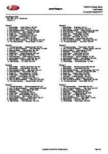
RESULTS Error statistics were computed from the position and velocity differences measured over the second half of the data arc for each case (approximately one and a half orbits). Radial, in -track, orbit-normal, and total errors in position and velocity are shown for each case in Figure 3. For each of these errors’ components, the mean, max, and standard deviation of the data are shown. In all cases, the mean total position and velocity errors were less than 7 meters and 3 mm/s. The highest mean position errors were seen in case C; the lowest position errors were under 1.5 meters for case A. Velocity errors were slightly larger for the lower altitude cases (A and B). Figure 4 provides error statistics for each case, compiled from processing the ten sets of software simulated measurements. The mean and standard deviations are computed by averaging the mean and standard deviations from each of the ten data sets. The maximum values shown are the maximum errors seen across all ten simulated data sets. In all cases the mean total position and velocity errors were less than 4 meters and 2 mm/sec. The highest mean total position errors were in case D, and again the lowest were in case A. The mean simulated results were slightly better than the mean real-time results; however, the maximum errors are actually larger in the simulated results, due in part to the fact that the software simulated results show the maximum observed over ten simulated data sets, while the real-time results represent only the maximum observed over a single run. Radial and in-track errors present in the real-time results (that do not appear in the simulated data) contribute to the larger total errors in the real-time cases. This is believed to be a measurement error in the receiver that in LEO data shows up primarily in the in-track and radial position components. Figures 5 through 8 provide representative plots for each orbital case. Each figure contains five plots: RSS position and velocity errors plus covariance envelope from the real-time test, RSS position and velocity errors plus covariance envelope for the software simulated results (all ten sets of results plotted), and finally the number of satellites tracked plotted against the user spacecraft altitude. The statistics on the number of measurements reported by the receiver and processed by the filter (shown in figures 5-8) were about 5% lower than the number of measurements processed in the software simulations. This is presumed to be due primarily to slight delays in the signal acquisition process and peculiarities of the satellite channel switching in the RF signal simulator. In case D, differences are slightly larger as there was actually a minor anomaly in the tracking
Presented at the ION National Technical Meeting, San Diego, CA, January 24-26, 2005.
6
performance of the receiver after approximately 30 hours elapsed time, resulting in some lost measurements near the end of the test. In each case, state errors were reduced significantly following one full orbital period. During periods of reduced GPS observability, some state parameters were not updated significantly, and errors can be seen growing during periods of zero GPS observability. In all but case C the filter appears to have converged to steady-state performance during the second orbit. Figures 9-12 show estimation errors for Cr, and the estimated clock drift compared against the point solution derived clock drift. There is evidence in some of the cases that the solar radiation pressure coefficient was not fully observable even after three orbits. In spite of being initialized with the correct value for both Cd and Cr, significant innovation went into Cr after each perigee pass. In Case D (Figure 12) the filter appears to converge to the proper value of Cr after the second orbit; however Case C (Figure 11) exhibits large errors in Cr that may contribute to the larger position and velocity errors seen in this case (Figure 7) when there is poor GPS observability. Drag was expected to be an insignificant orbital perturbation for all but case A, and although estimation of drag was turned on for all of the cases, little or no innovation went into the estimated drag coefficient for any of the other cases. The software simulated results (which are not plotted) were similar. Figures 9-12 also illustrate the properties of the clock states estimated by GEONS. Although there is no direct measure of the “clock truth” data (i.e., the actual drift of the GPS receiver clock during the test), the GEONS estimated bias and drift were compared against the bias and drift estimates from the receiver point solutions, when available. It is easy to see the strength of the Kalman filter and clock model in the estimation of the receiver clock drift, particularly during periods of poor GPS observability. In general, the maximum errors from the single set of measurements collected and processed in the real-time tests were bounded by the errors seen over multiple software simulations. This was the desired outcome, i.e., the settings chosen for the software simulation were sufficient to bound the actual errors present in data reported by a GPS receiver. Some additional improvements could likely be made by adjusting the filter tuning parameters and by addressing the biases in the measurements recorded by the GPS receiver. A GPS receiver’s clock normally has a significant drift, such that un-corrected, the receiver’s estimate of GPS time will be significantly in error. The PiVoT GPS receiver used in this study, like many other legacy receivers, outputs measurements that have been “corrected” to remove the bias and drift inherent in the internal clock. The PiVoT receiver; however, also
provides the precise bias and drift values that were applied by the receiver’s clock model in forming the measurements, so it is possible to recover the actual raw measurements made by the receiver. This is an important issue for this study, and indeed for any high altitude application of GPS-based orbit determination, regardless of whether the data is processed onboard in real-time, or on the ground. The only way the navigation filter will be able to properly estimate the drift of the receiver’s clock is if it processes the raw GPS measurements, before these effects have been removed. Most receivers output corrected measurements, after the receiver’s clock drift has been removed, but many do not provide all of the information that would be necessary to reconstruct the raw measurements.
FUTURE WORK This study summarizes some of the first rea l-time, high altitude orbit determination results obtained from tests conducted in the FFTB at GSFC, but a number of followon activities are planned. The real-time cases presented in this paper will be revisited in order to assess predictive accuracies associated with the definitive results presented here. Additionally, longer period orbital cases will be studied, including a geostationary satellite and a 24 hour period highly elliptical orbit. These cases, in which a GPS point solution will not necessarily be available for initializing the GEONS filter, will require the use of a batch filter initialization algorithm that is part of the GEONS software. There is also interest in assessing the ability of the navigation filter to recover from trajectory correction or station-keeping maneuvers, particularly for Geostationary orbits. Incorporating simulated maneuvers into a real-time test is an existing capability of the FFTB. Additional tests may be conducted which incorporate realistic errors for GPS ephemeris, clock, and ionosphere. These tests were conducted with a GPS receiver operating with conventional acquisition and tracking sensitivity, and using conservative assumptions for the receiving antenna configuration (a single omni-directional receiving antenna). Goddard is currently developing a new GPS receiver specifically designed for high altitude applications which will have an acquisition sensitivity approximately 10 dB lower than the receiver used in this study [2]. Furthermore the new receiver will have a more stable clock, and the GEONS software integrated within the receiver processor. The test cases presented in this paper will be re-run with the new GPS receiver in mid 2005 to assess the differences in performance from these improvements, which should be significant.
SUMMARY This paper has presented real-time orbit determination results obtained from hardware in-the-loop testing in a number of high Earth orbits. For the most challenging orbit simulated, a 12 hour Molniya orbit with an apogee of approximately 39,000 km, mean total position and
Presented at the ION National Technical Meeting, San Diego, CA, January 24-26, 2005.
7
velocity errors were approximately 7 meters and 3 mm/s respectively. Comparisons were made between the realtime results and those obtained processing software simulated measurements. Care was taken to use the same models and assumptions in the generation of both the real-time and simulated data. The worst mean errors from the software-simulated data were approximately 50% smaller, in large part due to biases present in the measurements recorded by the GPS receiver. Peak errors in the real-time results were generally smaller than the peak errors observed over ten software-simulated data sets. Some initial observations were also made with regards to the observability of the solar radiation pressure coefficient in these orbits, and the ability of the navigation filter to properly estimate the receiver clock bias and drift. The study has provided some valuable insights into how accurately our software measurement, clock, and other error models represent the true errors present in real measurements, and has helped to validate many of the settings and assumptions used in these software simulations. The performance obtained in this study is indicative of a dual frequency GPS receiver applying NASA’s real-time GDGPS corrections. Some real-time performance degradation was due to a known bias in the measurements from the GPS receiver tested. Improvements could also be achieved by utilizing directional antennas, a more sensitive receiver, a better receiver clock, or by further adjusting some of the tuning parameters in the GEONS filter. The FFTB test setup incorporates many realistic operational considerations and effects that are not normally captured in a software simulation. These include realistic procedures for initializing the receiver and Kalman filter, actual timing latencies due to messaging between the GPS receivers and flight processor, missing or lost data packets, measurement outliers, and so on. The result is a powerful tool for assessing onboard navigation performance in a wide range of orbital regimes, and a test-bed for developing software and procedures for use in real spacecraft applications.
ACKNOWLEDGEMENTS The authors would like to acknowledge the efforts of John Higinbotham and Bill Bamford of Emergent Space Technologies for their contributions to the development of the FFTB software and architecture.
REFERENCES 1. A. Long, D. Kelbel, T. Lee, J. Garrison, R. Carpenter, “Autonomous Navigation Improvements for HighEarth Orbiters Using GPS,” CNES 15th International Symposium on Space Flight Dynamics, Biarritz, France, June 26-30, 2000. 2. Winternitz, L., Moreau, M., Boegner, G., Sirotzky, S., “Navigator GPS Receiver for Fast Acquisition and Weak Signal Space Applications,” Proceedings of the Institute of Navigation GNSS 2004 Conference, Long Beach, CA, September, 2004. 3. Moreau, M., E.P. Davis, J.R. Carpenter, D. Kelbel, G.W. Davis, P. Axelrad, “Results from the GPS Flight Experiment on the High Earth Orbit AMSAT OSCAR-40 Spacecraft,” Proceedings of the Institute of Navigation GNSS 2002 Conference, Portland, OR, September 2002. 4. Moreau, M., Axelrad, P., Garrison, J., Wennersten, M., Long, A., “Test Results of the PiVoT Receiver in High Earth Orbits using a GSS GPS Simulator,” Proceedings of the Institute of Navigation GPS 2001 Conference, Salt Lake City, UT, September, 2001. 5. Czopek, F., "Description and Performance of the GPS Block I and II L-Band Antenna and Link Budget," Proceedings of the Institute of Navigation GPS 93 Conference, pp. 37-43, 1993. 6. Anon., Navstar GPS Space Segment / Navigation User Interfaces, ICD-GPS-200, Revision C, ARINC Research Corporation, January 14, 2003. 7. R. J. Muellerschoen, A. Reichert, D. Kuang, M. Heflin, W. I. Bertiger and Y. E. Bar-Sever, “Orbit Determination With NASA's High Accuracy RealTime Global Differential GPS System,” Proceedings of ION GPS-2001, Salt Lake City, UT, September 2001.
Presented at the ION National Technical Meeting, San Diego, CA, January 24-26, 2005.
8
Figure 3 – Real-time position and velocity error statistics (from a single hardware in-the-loop test for each case).
Figure 4 – Software simulated position and velocity error statistics (compiled from ten sets of results for each case).
Presented at the ION National Technical Meeting, San Diego, CA, January 24-26, 2005.
9
Figure 5 – Case A (circular LEO) position and velocity errors from real-time tests, position and velocity errors from software simulations, and number of satellites tracked plotted against receiver altitude. Presented at the ION National Technical Meeting, San Diego, CA, January 24-26, 2005.
10
Figure 6 – Case B (520x7800 MEO) position and velocity errors from real-time tests, position and velocity errors from software simulations, and number of satellites tracked plotted against receiver altitude. Presented at the ION National Technical Meeting, San Diego, CA, January 24-26, 2005.
11
Figure 7 – Case C (622x20200 km MEO) position and velocity errors from real-t ime tests, position and velocity errors from software simulations, and number of satellites tracked plotted against receiver altitude. Presented at the ION National Technical Meeting, San Diego, CA, January 24-26, 2005.
12
Figure 8 – Case D (1600x38900 HEO/Molniya) position and velocity errors from real-time tests, position and velocity errors from software simulations, and number of satellites tracked plotted against receiver altitude. Presented at the ION National Technical Meeting, San Diego, CA, January 24-26, 2005.
13
Figure 9 - Case A solar radiation pressure and clock drift states.
Figure 11 - Case C solar radiation pressure and clock drift states.
Figure 10 - Case B solar radiation pressure and clock drift states.
Figure 12 - Case D solar radiation pressure and clock drift states.
Presented at the ION National Technical Meeting, San Diego, CA, January 24-26, 2005.
14