0.294931485. 25,600. 87.773. 2.678029310. 256,000. 88.905. 27.129206158. 2,560,000 ... barrier counts, around hundreds of barriers, this ratio is around 20. p.
Hardware Supported Synchronization Primitives for Clusters Alberto F. De Souza1, Sotério F. Souza1, Cláudio Amorim2, Priscila Lima1 and Peter Rounce3 1
2
Departamento de Informática, Universidade Federal do Espírito Santo, Vitória-ES, Brazil Programa de Engenharia de Sistemas e Computação – PESC/COPPE, Universidade Federal do Rio de Janeiro, Rio de Janeiro-RJ, Brazil 3 Computer Science Department, University College London, London, United Kingdom
Abstract - Parallel architectures with shared memory are well suited to many applications, provided that efficient shared memory access and process synchronization mechanisms are available. When the parallel machine is a cluster with physically distributed memory, software based synchronization mechanisms together with virtual memory infrastructure can implement Software Distributed Shared Memory (S-DSM), a shared memory abstraction on a distributed memory machine. However, the communication network overload from the emulation can limit the performance of such systems. This problem motivated our research, in which we developed a set of synchronization primitives for S-DSM on reconfigurable hardware. This hardware implements an auxiliary synchronization network, which works in parallel to the data communication network. Experiments evaluating our hardware implementation against a software one showed that our system increases the performance of these S-DSM primitives by a factor of 40 or more. Keywords: Clusters, Distributed Synchronization, Barriers, Locks.
1
Introduction
Parallel machines can have shared or distributed memory. Shared memory parallel machines are easier to program than distributed memory ones mainly because the data structures manipulated by parallel algorithms can be more easily accessed in the former. However, shared memory parallel machines are harder, and consequently costlier, to implement. But, it is possible to use software, the virtual memory infrastructure and the data communication network of distributed memory machines to emulate shared memory systems [1]. These shared memory systems are known as Software-Distributed Shared Memory systems (S-DSM). In S-DSM systems many processors may possess a copy of a piece of the shared memory (e.g. a virtual memory page). Consistency among the copies of these shared items is guaranteed only at synchronization points of the computation.
Proper selection of synchronization points coupled with knowledge of the memory consistency model make programming S-DSM systems as easy as shared memory systems in most cases. The implementation of efficient S-DSM systems demands fast synchronization mechanisms. However, in many of such systems, synchronization mechanisms exchange messages between processors through the conventional communication network in competition with other traffic. These messages also pass through the network protocol layers, further slowing synchro-nization. Observation of these deficiencies motivated us to investigate the hardware implementation of distributed synchronization mechanisms. Hence, we have developed a distributed synchronization system, using reconfi-gurable hardware, where the processors of a cluster use a separate auxiliary synchronization network (Figure 1). To implement our distributed synchronization system we studied the synchronization mechanisms necessary for SDSM, evaluating the importance and viability of a hardware implementation of a subset of these. Our evaluations led us to implement two synchronization mechanisms: barrier and lock. Both are synchronization primitives heavily used in parallel processing. When associated with a group of processes, barrier has the property of not allowing any of them to proceed unless all members of the group have reached the barrier. Lock controls access to critical regions. Each lock has an associated token and, if a process needs to access the lock’s critical region, it must first request and acquire the token, or lock. Access to a lock by processes is mutually exclusive, so a process requesting the lock must wait if the lock is already held by another process. We have compared our hardware implemented barrier primitive with the same primitive implemented in software using MPI [2]. Our barrier was 40 times faster than the MPI_Barrier primitive. Our lock operated in a similar time to our barrier primitive.
3
Assistant Synchronization Network
SNI
SNI
SNI
SNI
PN0
PN1
PNn-2
PNn-1
CNI
CNI
CNI
CNI
Hardware synchronization mechanism
Our auxiliary synchronization network consists of a hierarchical network (Figure 2) that operates through messages sent by processors via 2 network elements: Nodes at the bottom associated with the processors, and Synchronizers in the upper levels. Layer 1
T.S.
Conventional Data Network 0
7
I.S.
CNI
Convencional Network Interface
PN
SNI
Assistant Synchronization Network Interface
Figure 1: Distributed synchronization system
2
0
Processor Node
Related Work
Two works in the literature present results relevant to our work: the Dietz et al. TTL_PAPERS [3] and the Hayakawa and Sekiguchi Synchronization and Communication Controller (SCC) [4]. TTL_PAPERS [3] is an implementation in TTL hardware of Purdue's Adapter for Parallel Execution and Rapid Synchronization (PAPERS [5]). This hardware makes use of the parallel ports of a cluster’s computers in conjunction with some simple external hardware for the implementation of a barrier. A single barrier is made available and all processors of the cluster are members of a single group, so that they synchronise at this one barrier. The hardware described does not implement locks. The shorter time for barrier synchronization in TTL_PAPERS is 2.5µs for a 4 processor cluster, and it is estimated that this would not change with the number of PEs. However, the design of the external hardware changes and its complexity increases with PE number, and an extendable system might well have barrier synchronization times that increase with PE count. Our hardware obtained barrier synchronization times of 1.686µs on average, which would increase logarithmically with PE count. We cannot perfectly compare these times with TTL_PAPERS, as its experiments use processors with lower frequencies than those in ours. The SCC [4] implements barriers for clusters using specialised PCI boards that are inter-connected in a onedimensional daisy-chain by 40-way cables such that messages from one end to the other traverse all the nodes. The “synccomm” network produced by the boards provides a dedicated synchronization network separate from the conventional network, as does our auxiliary network. As with the TTL_PAPERS, just a single barrier is available, but a sub-set of the processors can be selected to participate in the barrier, and again lock was not provided. Barrier synchronization times in SCC were 3.2µs and 6.2µs for two and four processor clusters respectively, whereas experiments on our hardware with 2-processor clusters gave results inferior than 2µs on average.
7
I.S.
56
I.S.
0
63
I.S.
7
Node
Top Syncher
504
511
Node
I.S.
Layer 3
I.S.
Node
T.S.
Layer 2
I.S.
Layer 4
Node
Intermediary Syncher
Node
Processor Node
Figure 2: Topology of the auxiliary network Our requirements for synchronization were for this auxiliary network to carry 4 types of messages: two for the barrier and two for the lock. We augmented these with two further messages: reset and broadcast. The reset message initializes the Global Clock, an extra facility provided by the synchronization network [6], while broadcast provides a general-purpose message distribution capability. The auxiliary network is designed on the premise that downward messages are broadcast to all lower level elements – the Intermediate Synchronizers (IS) retransmit all such messages to all lower level elements such that they are received synchronously. Barriers are implemented by masks distributed across the Synchronizers. For a particular barrier (there may be more than one), a synchronizer holds a mask, the bits of which indicate which of its sub-trees participate in the barrier: for the synchronizers in the level above the Nodes, the mask bits indicate which of its attached Nodes are in the barrier. Figure 3 illustrates the general format of the messages. 1
start bit
C0
C1
command
C2
D0
D1
Dn
data
0
stop bit
Figure 3: General format of a message A message is detected through a start bit – a transition from inactivity (logic 0). After this bit, three command bits are sent containing the message code, which indicate the operations to be carried out. A number of data bits, varying from zero to 76, follow, and a message terminates with the control stop-bit, forcing the line to inactive. Of the 8 commands available, only 6 are used with the rest reserved for future use. The six commands, or message types, are detailed below: reset. Initializes the Global Clock. This command is passed up in the hierarchy of Synchronizers until it reaches the top. Then, it goes down initializing all the Node Global
Clock counters by synchronously arriving at each of the Nodes [6]. A reset message has no data bits. barrier. Creates a barrier. This message traverses the network to the top, configuring a barrier. All Nodes participating in the barrier send a barrier creation message, though not all reach the top. Synchronizers that have already come in contact with the barrier message do not propagate it up. Barrier mask information is propagated as data via these messages to the Synchronizers indicating who participates of the barrier. barrier reaching. Informs the Synchronizer that a particular barrier has been reached. When all Nodes or Synchronizers connected to a particular Synchronizer have indicated that they have reached a barrier, this Synchronizer informs the one above it of this fact, unless it is the Top Synchronizer, when the barrier is considered to be completed. At this point, the Top Synchronizer sends a message of the same kind down the hierarchy to signal that the barrier has completed. Barrier masks in the Synchronizers have their bits cleared as this message propagate downward. broadcast. Disseminates a message with a 76-bit data field throughout the network. The data content is user defined. A broadcast message first goes up the hierarchy and then goes down to reach all Nodes. lock acquire. Requests a lock. A lock request traverses the network to the top. If the Top Synchronizer verifies that the lock is free, it sends a lock acquire message down the tree, giving all Nodes the ID of the lock’s acquiring Node, otherwise the message is discarded. lock release. Frees a lock. The message traverses the network to the top before being broadcast down, informing all Nodes that the lock has been freed.
3.1
Memory and broadcasts a barrier reaching message downwards. Messages of type lock acquire request the acquisition of a specific lock. If the lock is available, the Locks Memory is updated with the identifier of the Node requesting the lock and a lock acquire message is broadcast down the network, signalling the acquisition of the lock and the acquiring processor ID. If the lock is unavailable, the message is discarded. Unsatisfied requests cause requesting processors to wait until a lock release for this requested lock is received. After that, the lock request can be re-tried. Messages of type lock release update the Locks Memory and generate a lock release broadcast signalling the availability of the lock. Transmitter Down has only one message store, since each message is always sent out on all 8 outgoing serial links to the lower hierarchical levels.
Pulse generator Net_clk
FPGA
Barrier Memory Core Control Lock Memory
Control Data
Transmitter Down
Receiver Down
The Top Synchronizer
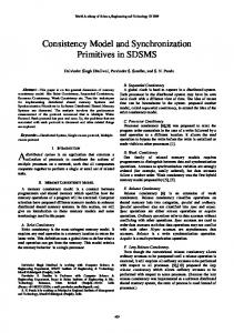
The Top Synchronizer (TS), see Figure 4, is unique, occupying the root of the auxiliary network tree. It is responsible for the control of creation and liberation of barriers, and for the granting of all locks. The TS has eight incoming and outgoing serial ports for communication with the next lower level of the network. At the top right of Figure 4 is shown the 64 MHz Pulse Generator that synchronizes the auxiliary network and increments the Global Clock. Receiver Down has an 8-entry store for incoming messages on its 8 incoming serial links. It signals the control core with the identity of the incoming port on which a message has been received. The control core reads the message via the internal bus, identifies the type and acts accordingly. Messages of type reset and broadcast are sent on all outgoing serial ports without any local action. Messages of type barrier cause the synchronizer to create the barrier. On receipt of the first message about the creation of a specific barrier, the barrier memory is updated; subsequent barrier messages for this same barrier are discarded. With messages of type barrier reaching, the TS records, in the Barriers Memory, the receipt of each message for a particular barrier, until it has received such messages from all sub-trees involved in the barrier, at which point it updates the Barriers
Net_clk
Rx_down_0-7
Tx_down_0-7
FPGA Borderline
Sync_bsy_0-7
Net_clk_0-7
Net_clk Frequency Field
Figure 4: The Top Synchronizer
3.2
The Intermediate Synchronizer
The Intermediate Synchronizer (IS), which implements the interior nodes of the network tree, are shown in Figure 5. The Receiver Down and Transmitter Down are the same as in the TS: concentrating incoming messages from lower levels, and broadcasting outgoing messages on all links. Transmitter Up and Receiver Up units handle single message transfers with the immediately superior Synchronizer. Receiver Up makes received messages available over the internal data bus to other elements as soon as the data of the message is available. The control core executes according to the message’s command. Downward messages are forwarded via Transmitter Down to all lower level elements immediately in
order to provide for synchronous receipt across the network in as few cycles as possible. The only internal processing is for downward messages of type barrier reaching, when the IS barrier memory is updated, freeing the barrier locally. For upward propagating messages of types reset, broadcast, lock acquire and lock release, the control core just commands their retransmission via Transmitter Up. Messages of type barrier require that the Barriers Memory is accessed to verify if the specified barrier has already been created: if so, the control core discards the message; if not, the barrier is created locally and the message is sent upwards, discarding the barrier mask relative to the current level. A barrier creation message has its size reduced by 8 bits each time it is forwarded. Messages of type barrier reaching update the Barriers Memory by clearing the bit in the barrier mask for the sub-tree from which the message arrived. If this is the last of the mask bits to be zeroed, the message is sent up the network; if not, the message is not forwarded, but discarded. Tx_up
Rx_up Sync_bsy
positive transition of the clock signal – Net_clk –, coming from the Top Synchronizer. The network design has been implemented to guarantee that all Nodes receive the Global Clock and any reset message at the same instant. Therefore, it can be assured that the counters of Nodes are initialized and/or incremented in a synchronous manner, holding the same counting (time) value at each clock cycle. Tx_up
Rx_up Net_clk
Sync_bsy HOTII Board FPGA
Global Clock
Transmitter Up
Receiver Up Net_clk
Barrier Memory Core Control
Lock Memory
Net_clk
FPGA Broadcast Memory Transmitter Up
Barrier Memory
Receiver Up
PCICore
Data Control
Control Data Pci_clk
Core Control
PCI BUS HOTII Board FPGA Borderline
Receiver Down
Frequency Pci_clk domain
Transmitter Down
Figure 6: Blocks diagram of Node
Net_clk
Rx_down_0-7
Sync_bsy_0-7
FPGA Borderline
Tx_down_0-7
Net_clk_0-7
Net_clk Frequency Field
Figure 5: The Intermediate Synchronizer
3.3
Frequency Net_clk domain
The Node
The Node, structure shown in Figure 6, consists of a PCI board installed inside each computer to implement the lowest level of the network. Memory within the board is mapped to processor addresses over the PCI bus [7]. To send a message, the Node processor (NP) writes it to a specific address in the PCI bus interface. To discover if a barrier has been reached, the NP reads from a set of 256 addresses, each one corresponding to a barrier. Lock status (free / not free) is read from another set of 256 addresses, each one corresponding to a lock. Broadcast messages are read from a range of 1024 addresses that form a circular list, each address corresponding to a specific broadcast message. Implementation of the Global Clock requires a 64-bit counter in each Node [6], which is incremented at each
Receiver Up and Transmitter Up are essentially the same as in the IS. The control core is the element responsible for treating the messages deriving from the PCI bus and Receiver Up. All messages, without exception, coming from the PCI bus are transmitted upwards. All messages received from the network via the Receiver Up require action from the control core. Of the messages originated at the PCI bus, the barrier ones require that the Barriers Memory of the Node be updated, creating the barrier. When a downward reset message is received, the Global Clock counter is reinitialized. For downward messages, barrier reaching and lock release, the Barriers and Locks Memory are updated respectively. Downward broadcast messages are stored in the Broadcast Memory, along with the lower-order 48 bits of the Global Clock, which record their reception time. Downward lock acquire messages update the Locks Memory with the identifier of the acquiring Node.
4
Methods
To perform validation and evaluation tests of the system developed, we implemented the hardware in H.O.T. II FPGA development boards [8]. Such a board consists of the basic
operational circuitry, memory banks and a model XC4062XLA–HQ240 FPGA, made by Xilinx [9]. The FPGAs development tool chosen was also from Xilinx. The experimental system, shown in Figure 7, has a 2-level hierarchy with just 2 Nodes and a Top Synchronizer, but no Intermediate Synchronizers. Each element is a microcomputer with attached H.O.T. II board, programmed to be either a Node or a TS. Category 5, Shielded Twisted Pair (STP) cables of 5m length with 4-pairs are used to connect the elements.
unsigned int j = atoi(argv[1]) ; MPI_Init(&argc, &argv) ; MPI_Comm_rank(MPI_COMM_WORLD, &my_rank) ; MPI_Comm_size(MPI_COMM_WORLD, &num_procs) ; MPI_Barrier(MPI_COMM_WORLD) ; unsigned long start_all = SyncGetTsc() ; for (k=0;k