Implementation of different boundary conditions (i.e. Dirichlet, Neumann and mixed ..... invertible matrix M such that the condition number of the system Mâ1Ay ...
Hierarchical Adaptive Cross Approximation GMRES Technique for Solution of Acoustic Problems Using the Boundary Element Method ∗
∗
A. Brancati, M. H. Aliabadi , I. Benedetti
∗,†
Abstract In this paper a new Rapid Acoustic Boundary Element Method (RABEM) is presented using a Hierarchical GMRES solver for 3D acoustic problems. The Adaptive Cross Approximation is used to generate both the system matrix and the right hand side vector. The ACA is also used to evaluate the potential and the particle velocity values at selected internal points. Two di�erent GMRES solution strategies (without preconditioner and with a block diagonal preconditioner) are developed and tested for low and high frequency problems. Implementation of di�erent boundary conditions (i.e. Dirichlet, Neumann and mixed Robin) is also described. The applications presented include the problem of noise acting on a row of aircraft seats and problem of engine noise emanating from the Falcon aircraft. For the �rst example, the new RABEM is shown to be faster than the Fast Multipole Methods. The tests demonstrated that the new solver can achieve CPU times of almost O(N) for low frequency and O(NlogN) for high frequency problems. ∗ Department † On
of Aeronautics, Imperial College London, South Kensington, SW7 2AZ, UK
leave from DISAG Dip.
Ing.
Strutturale Aerospaziale Geotecnica, Università degli Studi di Palermo,
Palermo, Italy
1
1
Introduction
The Boundary Element Method (BEM) is one of the most general and e�cient numerical technique for solving acoustic problems [Wrobel and Aliabadi
(2002)].
The boundary element
discretisation of the surface of the problem leads to a non-symmetric and fully populated system matrix. For a standard BEM formulation both the memory storage and the setting up of the
2
system matrices are of O(N ), where
N
denotes the degree of freedom. Moreover, direct solvers
3
2
require O(N ) operations while iterative solvers O(kN ), where
k
is the number of iterations.
To overcome the di�culties related to storage and solution time a number of techniques have been proposed which include using block-based solvers [Crotty (1982); Rigby and Aliabadi (1995)], lumping techniques [Kane and Kumar
(1990)] and iterative solvers [Mansur, Araújo
and Malaghini (1992)]. The Adaptive Cross Approximation (ACA) is an e�ective technique for solving non-symmetric and fully populated matrices and decreases the CPU time signi�cantly (see Bebendorf and Rjasanow example, Von Estor� et al.
(2003)) and has been applied to the Helmholtz equation by, for
(2005). The solution of linear system of equations is accelerated
by calculating only few entries of the original matrix. matrix into two rank (
low
and
full
The basic idea is to divide the whole
rank) blocks based on (ACA) size and distance between a
group of collocation points and a group of boundary elements. The ACA algorithm has been applied to the low rank blocks achieving approximately O(N ) for both storage and matrixvector multiplication [Benedetti, Aliabadi and Daví
(2007)]. An alternative approach to the
fast BEM solver is the Fast Multipole Method (FMM) (see for example Aoki, Amaya, Urago and Nakayama and Lim
(2004); Chew, Song, Cui, Velamparambil, Hastriter and Hu
(2008); Wang and Yao
(2005, 2008)).
(2004); He, Lim
Although FMM techniques are e�cient for
the fast solution of boundary element problems, their main disadvantage is that the knowledge of the kernel expansion is required in order to carry out the integration; all the terms of the series needed to reach a given accuracy must be computed in advance and then integrated, which can lead to a signi�cant modi�cation of the integration procedures in standard BEM codes.
From an algebraic point of view however, the integration of a degenerate kernel, i.e.
of a kernel expanded in series, over a cluster of elements corresponds to the approximation of
2
the corresponding matrix block by a low rank block. Comparison between the FMM and ACA method were made by Wang, Hall, Yu and Yao (2008) for three-dimensional Laplace problems. In their study a fully pivoted ACA was shown to require considerably more computational e�ort than FMM. However, it must noted that the full pivoted approach is well know to be much slower than partially pivoted approach developed in our paper. The main reason behind this is that fully pivoted approach requires the knowledge of the full matrix whereas the partially pivoted approach would only require generation of individual matrix entries. Indeed, in our paper the partially pivoted ACA approach for acoustic problems is shown to be superior to the FMM for an example considered. Developing iterative solvers for non symmetric linear systems has been widely investigated. One of the most popular is the generalized minimal residual method (GMRES) proposed by Saad and Schultz
(1986) and further developed by other authors [Leung and Walker
Merkel, Bulgakov, Bialecki and Kuhn
(1997);
(1998); Amini and Maines (1998)].
In this paper a new hierarchical adaptive cross approximation technique coupled with GMRES is presented for 3D boundary element solution of Helmholtz problems. Particular attention is paid to implementation of di�erent types of boundary conditions (i.e. Dirichlet, Neumann and mixed Robin) into the ACA solution algorithm. The ACA and the
H -Matrix
format are also
employed for the post processing steps required to evaluate the values of the potential and particle velocity at the internal points. The constant elements are utilized to discretize the problem. Initially two simple benchmark problems of the pulsating sphere and of the scattering of a plane wave from a rigid sphere are investigated. Next, large scale applications of involving a row of three seats representing the seats in an aircraft cabin and noise emanating from engines of the Dassault Falcon aircraft are presented. The tests carried out show that the new assembly and solution technique can achieve CPU times of almost O(N ) for low frequency and O(N for high frequency problems.
3
log N )
2
The Boundary Element Method
In this section the three dimensional Boundary Element Method (BEM) for sound propagation problems is brie�y reviewed. The boundary integral formulation for sound propagation can be written as
ˆ 0
ˆ
0
j
∗
C(x )u (x ) +
0
q (x , x)u(x)dΓ(x) = Γ
ˆ ∗
0
u∗ (x0 , Xs )
u (x , x)q(x)dΓ(x) + Γ
Ω
1 b(Xs )dΩ(Xs ) c2 (1)
where
u(x)
u∗ (x0 , x)
and
and
q(x)
denote the potential and �ux, respectively on the boundary
q ∗ (x0 , x)
Γ.
The terms
are the potential and the �ux fundamental solutions, respectively, and
C(x0 ) is the free term which its value depends on the position of x0
on the boundary (see Wrobel
and Aliabadi (2002)). The last term refers to the presence of sources within the domain strength
b(Xs )/c2 where c
Ω with
is the sound velocity. The BE formulation automatically satis�es the
Sommerfeld radiation condition [Wrobel and Aliabadi
(2002)].
The boundary integral equation (1) is discretised with constant elements. The discretised form of (1) can be written in a matrix form as
HU = GQ + P(Xs ) where
H
and
G
are
N ×N
(2)
coe�cient matrices corresponding to integrals of the product of
the Jacobian of transformation with �ux and potential fundamental solutions, respectively, and
U
and
Q
are the
N ×1
potential and �ux vectors, respectively.
equation (1) produces the
N ×1
vector
P,
created by
NP
Finally, the last integral in
sources within the domain
Ω.
The implementation of the boundary conditions for acoustics wave equations has received much attention in the last decades.
In particular Clayton and Engquist
(1977) and more
recently Higdon (1992) included the absorbing boundary conditions for acoustic simulations in their computing numerical models. The possible presence of absorbent material with a certain value of impedance has also been introduced by a quantity that relates directly the potential and the �ux, here called
arti�cial admittance (ζ ) which is de�ned as follows 4
ζ(ω) =
q u
(3)
Equation (3) creates the impedance boundary conditions and can be easily accounted for in (2). After substitution of the prescribed boundary conditions, the resulting system of algebraic equations may be written as
AY = F where
Y
(4)
is the vector containing the unknown boundary potentials and �uxes,
matrix which is non-symmetric and densely populated, and
F
A is a coe�cient
is obtained by multiplying the
prescribed boundary conditions by the corresponding columns of the
G
and
H
matrices.
Similarly, for internal potential values the resulting system of equations can be written as
U(X) = −HU + GQ + P(Xs ) where
H
and
G
are similar to
H
and
G,
(5)
but evaluated at internal points (N I ), and for the
internal particle velocity
0
0
U0 (X) = −H U + G Q + P0 (Xs )
(6)
0
where superscript � � denotes derivative with respect to Cartesian coordinates (x, and
G
0
contain the integrals of the derivatives of the fundamental solutions and are
matrices calculated by substituting the fundamental solutions derivatives (see Dominguez (1993)) and
P0 (Xs )
is a
NI × 1
u∗ (x0 , x)
q ∗ (x0 , x)
NI × N and their
vector containing the contribution
to the particle velocity generated by the sources within the domain
3
and
0
y , z ); H
Ω.
Hierarchical BEM for Acoustics
The use of hierarchical matrices [Hackbush Grasedyck and Hackbush
(1999); Hackbush and Khoromskij
(2000); Borm,
(2003)] for the representation of BEM system of equations, in con-
5
junction with Krylov subspace methods [Leung and Walker (1997); Merkel, Bulgakov, Bialecki and Kuhn
(1998)], is extended to BEM acoustic problems with di�erent boundary conditions.
The technique speeds up the computation, whilst maintaining the required accuracy and saving on the memory storage.
3.1
Matrix Assembly using the Collocation Method
The hierarchical representation of a boundary element matrix can be regarded as a subdivision of the matrix itself into a collection of blocks, some of which, called a special compressed representation, while others, called
low rank blocks,
full rank blocks
allow
are represented in
their entirety. The subdivision and the subsequent classi�cation is achieved starting from the boundary element mesh and is based on the grouping of the nodes and elements into clusters of
close
nodes and elements. A block populated by integrating over a cluster of elements whose
distance, suitably de�ned, from the cluster of collocation nodes is above a certain threshold is called
admissible
and it can be represented in the low rank format. The remaining blocks are
generated and stored in their entirety. The process leading to the subdivision in sub-blocks and to their further classi�cation is based on a preliminary
hierarchical partition
of the matrix index set aimed at grouping subsets
of indices corresponding to contiguous nodes and elements, on the basis of some computationally e�cient geometrical criterion. The process starts from the complete set of indices where
n
I = {1, 2...n}
denotes the number of collocation points. This initial set constitutes the
tree. Each cluster in the tree, called
root
of the
tree node (not to be confused with geometrical discretisation
nodes) is split into two subsets, called
sons,
on the basis of some selected criterion. For this
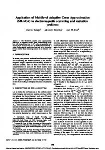
study the longest extended dimension of the whole geometry (step 1 of the �gure 1) is detected �rst and its central point calculated. This point divides the mesh into two tree nodes (step 2). The geometries of the mesh of each of these blocks is then divided into two other tree nodes by following the same procedure (step 3). Such an iterative procedure is repeated until each tree node is constituted by a smaller number of elements than the cardinality. The common tree node from which two sets originate is called the
6
parent.
The tree nodes
that cannot be further split are the
leaves
of the tree. Usually a tree node cannot be further
split when it contains a number of indices equal to or less than a minimum number called
cardinality
index subsets, or hierarchical
Figure 1:
block
nmin ,
of the tree, previously �xed value. This partition is stored in a binary tree of
cluster tree,
that constitutes the basis for the subsequent construction of the
subdivision, that will be stored in a quaternary
block tree.
A schematic of the �rst two iterations of the cluster tree creation:
1) the whole
geometry is divided 2) into two parts, each of which is then subdivided again 3) into two parts.
The block tree is built recursively starting from the complete index
I×I
(both rows and
columns) of the collocation matrix and the previously found cluster tree. The objective of this process is to split hierarchically the matrix into sub-blocks and to classify the leaves of the tree
7
into admissible (low-rank) or non admissible (full-rank) blocks. The classi�cation is based on a geometrical criterion that assesses the separation of the clusters of boundary elements associated to the considered block. Such a criterion relates directly to the boundary mesh. Let
Ωx0
denote the cluster of elements containing the discretisation nodes corresponding to
the row indices of the considered block and
Ωx
the set of elements over which the integration is
carried out to compute the coe�cient corresponding to the column indices. The admissibility condition can be written as
min(diam Ωx0 , diam Ωx ) ≤ η · dist(Ωx0 , Ωx ) where
η>0
(7)
is a parameter in�uencing the number of admissible blocks on one hand and the
convergence speed of the adaptive approximation of low rank blocks on the other hand [Borm, Grasedyck and Hackbush
(2003)].
Since the actual diameters and the distance between two clusters are generally time consuming to be exactly computed, the condition is usually assessed with respect to bounding boxes parallel to the reference axes [Giebermann and
Ωx
(2001); Grasedyck
in the equation (7) are replaced by the boxes
Qx0
and
Qx .
(2005)]. In this case
Ωx0
The bounding box clus-
tering technique adopted in the present work is generally used for its simplicity, although it produces non-optimal partitions that can be improved by suitable procedures, as will illustrated next. Other clustering techniques able to produce better initial partitions have been proposed in the literature. The construction using the
principal component analysis
[Bebendorf
(2006)]
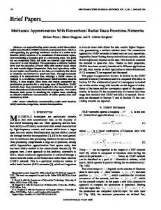
signi�cantly improves the quality of the initial partition. The algorithm is graphically illustrated in the �gure 2. Starting from the root (the entire matrix), each block is subdivided into four sub-blocks until either the admissibility condition is satis�ed or the block is su�ciently small that it cannot be further subdivided. The clear grey boxes represent low rank blocks while the dark grey boxes are the full rank ones.
8
Figure 2: A schematic presentation of the �rst three iterations that form the block tree.
An admissible block can be represented in low rank format. Such representation constitutes an approximation of the discrete integral operator based, from the analytical point of view, on a suitable expansion of the kernel of the continuous integral operator [Bebendorf and Rjasanow (2003); Tyrtyshnikov
(1996); Goreinov, Tyrtyshnikov and Zamarashkin
(2000)]. This expansion, and consequently the existence of low rank the
(1997); Bebendorf
approximants,
asymptotic smoothness of the kernel functions [Bebendorf and Grzhibovskis u∗ (x0 , x)
the fact that the kernels
and
q ∗ (x0 , x)
are singular only when
is based on
(2006)], i.e. on
x0 = x.
Asymptotic
smoothness represents a su�cient condition for the existence of low rank approximates.
For
more detailed information about asymptotic smoothness the readers are referred to the works [Bebendorf and Rjasanow Let
C
be an
m×n
(2003); Bebendorf (2000)].
admissible block. It admits the low rank representation
C ' Ck = A · B T =
k X
ai · bTi
(8)
i=1 where
A is of order m×k and B
The approximating block the
Frobenius norm
and
Ck ε
is of order
n×k , with k being the rank of the new representation.
satis�es the relation
kC − Ck kF ≤ εkCkF ,
where
k · kF
represents
is the set accuracy. Sometimes it is useful to represent the matrix
using the alternative sum representation, where
9
ai
and
bi
are the
i − th
columns of
A
and
B,
respectively. The approximate representation allows storage savings with respect to the full rank representation and speeds up the matrix-vector product [Grasedyck and Hackbusch (2003)]. The low rank blocks are built by computing and storing only original blocks. Such entries allow for computation of the columns
some ai
of the entries of the
and
bi
of the representa-
tion [8] through suitable algorithms, known as adaptive cross approximation (ACA) [Bebendorf and Rjasanow
(2003); Bebendorf
collocation matrix accuracy
εc
(2000)].
The ACA algorithms allow to reach the selected
adaptively. The stopping criterion is based on the assessment
of the convergence of the approximating block in terms of the Frobenius norm [Bebendorf and Rjasanow
(2003); Bebendorf
(2000)]. Once the
k − th
couple
(ak , bk )
has been computed the
Frobenius norm of the approximation can be computed by the following recursive formula
kCk k2F = kCk−1 k2F + 2
k−1 X
(aTk ai )(bTi bk ) + kak k2F kbk k2F
(9)
i=1 where
ak
and
bk
represent the column and row computed at the
k − th
iteration. A suitable
stopping criterion can be expressed as
kak kF kbk kF ≤ εkCk kF
(10)
that prescribes to stop the iteration when the inequality is satis�ed for a required preset accuracy
ε.
3.2
Boundary Conditions and Right Hand Side Setting
By applying the ACA, the actual setting of the �nal system for mixed boundary condition problems requires some additional considerations.
In this work di�erent types of boundary
conditions are considered in such a way that rigid, soft and absorbing surfaces can all be studied in order to simulate a real situation and to perform an eventual parametric analysis. An initial routine selects the matrix that is calculated �rst based on the boundary conditions that are predominant for that block. If the �ux (or potential) is predominant then the matrix
H
(or
G)
is calculated �rst, otherwise, in the case the boundary condition are in terms of impedance, the
10
ACA algorithm is applied to both the matrices. In order to speed up signi�cantly the system solution of equation (4) the �
BlockNode �
pointer
suggested by Benedetti, Aliabadi and Daví is used here. The contributions of each block to the solving matrix
A
is stored in the BlockNode pointer and calculated at each step as well as the
contribution of the right hand side vector that is, instead, stored in the global vector
F
to save
memory. The ACA algorithm is applied to one or both of the matrices
G
and
H
depending upon the
boundary conditions that are predominant for each block matrix. Particular care must be taken when not pure Dirichlet, Neumann or mixed Robin conditions are applied. There may be four di�erent cases:
a)
BCs mainly in terms of �ux (or potential) except for the
k th
value expressed in terms
of potential (or �ux).
As an example, one can consider that the boundary conditions are expressed in terms of �ux (the �rst block matrix calculated with ACA is potential. A routine replaces each the opposite in sign of the at the
k th
k th
b)
and at the node
k
is expressed in terms of
value of each row previously calculated with zero, adds
column of the
G
block matrix and also adds a zero row with 1
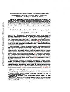
element (see �gure 3).
Figure 3: Substitution of the
G
k th
H)
k th
values of each row with zero, addition of the
block matrix and of a zero row with
1
at the
k
th
BCs mainly in terms of �ux except for the
11
k th
column of the
element.
k th
value expressed in terms of impedance.
Here simply add the arti�cial admittance
k th ζ
column of the
G
block matrix not yet calculated multiplied by the
opposite in sign, and adds a zero row with 1 at the
k th
element (see
�gure 4).
Figure 4: Addition of the tance
ζ
k th
column of the
G
opposite in sign and of a zero row with
c)
block matrix multiplied by the arti�cial admit-
1
at the
k th
element.
BCs mainly in terms of potential except for the
k th
value expressed in terms of
impedance.
In this case multiply the admittance
ζ
k th
row of the
G
block matrix (previously calculated) by the arti�cial
opposite in sign. Then another routine adds the
not yet calculated and a zero row with 1 at the
Figure 5: Multiplication of the opposite in sign, addition of the the
k th
k th k th
row of the
k th
G
column of the
element.
12
k th
column of the
H block matrix
element (see �gure 5).
block matrix by the arti�cial admittance
H
block matrix and of a zero row with
1
ζ at
d)
BCs mainly in terms of impedance except for the
k th
value expressed in terms of
potential (or �ux).
In this case the ACA algorithm acts earlier on the reached and the
k th
and the
k th
block matrix. If the ACA stop criterion is
k th
value is in terms of potential, the
zero. The ACA algorithm is �nally applied to the
−ζ ,
H
G block matrix whose columns are multiplied
elements of its rows are divided by
Figure 6: Substitution of the
k th
value of each row calculated is set to
ζ
(see �gure 6).
values of each row with zero, addition of the columns of the
G
block matrix multiplied by the arti�cial admittance opposite in sign and of its rows where the
k th
elements are divided by
ζ.
Regarding the setting up of the right hand side vector some additional considerations are required as explained next. Recalling the ACA algorithm, the routine that calculates the of one of the block matrices
G
or
H
also calculates the
ith
ith
row
row of the other block matrix. Thus,
the right hand side contribution of that row for the block matrix analyzed is directly calculated. Now, there are two main cases to analyze.
•
BCs mainly in terms of �ux (or potential).
Here, one may need to apply the ACA on the matrix
G
(or
H).
In fact, if all the boundary
conditions are zero, there is no need to calculate the contribution of the block matrix to the �nal right hand side and another block matrix can be analyzed. Moreover, owing to the fact that the number of entries needed for the ACA is, in most the cases, equal for both the block matrix
G
and
H,
may be convenient to calculate the contribution to the right hand side with a
standard procedure (see appendix).
13
•
BCs mainly in terms of admittance.
Once the ACA as been applied to the block matrix hand side vector
F, due to the presence of the k th
H,
the possible contribution to the right
value of the boundary conditions expressed in
terms of potential, is easily calculated by multiplying each column of the ACA to the
k th
value
of each row with opposite in sign. Finally, if the ACA algorithm applied to the block matrix
G
is also successful reached, the contribution to the right hand side of the eventual presence of the boundary condition expressed in terms of �ux is clearly calculated.
3.3
System Solution
Once the hierarchical representation of the collocation matrix has been established, the solution of the system can be computed through iterative solvers with or without preconditioners. When the condition number is high it slows down the convergence rate, as is often the case when dealing with BEM systems, a preconditioner can be computed taking full advantage of the representation in hierarchical format. invertible matrix
M
For
Ay = F
system a left preconditioner is an easily
such that the condition number of the system
M −1 A y = M −1 F
results
lower than the original one, improving thus the convergence rate of the iterative solver. In the present work a GMRES iterative solver [Saad and Schultz (1986)] without and with preconditioner are used for the solution of the system of equations.
The method, proposed
by Saad and Schultz (1986) and further developed by many other author, is a Krylov based iterative method for the numerical solution of a system of linear equations, as in equation (4). The Arnoldi iteration is used to form a basis for the Krylov subspace. In all the on-line complex GMRES routines available for FORTRAN, the generation of the whole matrix
A
is needed. In the present work the whole matrix is never calculated, resulting
N ) procedure.
in a reduction in memory requirements. The routine adopted is an O(
Internal Points The ACA algorithm can also be used to speed up the calculation of potential and particle velocity at internal points from the boundary values of potential and �ux. To achieve this, a
14
cluster tree for the internal points is generated following the procedure seen at the beginning of this section. Thus the hierarchical tree is generated by considering the columns and the rows of the block matrices
H, G, H
0
and
G
0
(see equations (5) and (6)). The ACA procedure is applied
four times to all the matrices. The name of such a pointer, the values of the parameters
cardinality
η
and
remain unchanged and hence the same routines as for the boundary points can be
applied.
4
Numerical Results
In order to demonstrate the e�ciency of the proposed method a series of numerical tests have been performed. Comparisons with the standard BEM with a direct solver [Dominguez (1993)], with LMS Virtual.Lab [LMS International (2008)] and with Fast Multipole Method (FMM) for acoustics [FastBEM Acoustics (R)] shows that the formulation presented here can signi�cantly reduce the system solution time. All of the numerical simulations were executed on a Xeon(TM) CPU 3.00GHz processor with 2GB of RAM. In all the simulations performed the value of the parameter
η =10 and the cardinality is set to
22. These values are found to give the best performances. Moreover, the value of the cardinality is quite restricted. In fact, as this value decreases, the stopping criterion of equation (10) is not successful for many low rank blocks, rather, it increases the CPU time due to bigger full block dimensions. The value of the parameter
η
can be modi�ed between 1 and 1000 without loss of
accuracy and resulting in a 5% CPU time acceleration. Furthermore, the optimum value of this parameter depends upon the geometry and the elements of the mesh. Concerning the storage memory requirements of the matrix
A,
�gure 7 shows the block-wise
structure of the collocation matrix as generated by the ACA algorithm for a pulsating sphere constituted with 6100 elements for four di�erent values of
η
(1, 2, 4 and 10). The tone of grey
is proportional to the ratio between the memory required for the low rank representation and the memory required for a standard format. Hence black blocks stand for the full rank block matrix, while almost white blocks are those for which the ACA compression works better.
15
Figure 7: Block-wise representation of the ACA generated matrix for
η = 1, η = 2, η = 4
and
k
and
η = 10.
RABEM vs. SBEM vs. LMS The problem of the sound radiated by a pulsating sphere with radius, wave number
uniform radial velocity all equal to unity is investigated. The acoustic wave velocity and the medium density are set equal to unity. The three-dimensional scalar wave propagation problems
16
using constant boundary elements [Dominguez
(1993)], will be referred to as �SBEM�, and is
used for comparison purposes. Table 1 compares the two codes speed up ratio (de�ned as CPU time of SBEM divided by CPU time of RABEM) for setting up the system solution, �nding the solution and for the total time for eight di�erent mesh accuracies. The percentage error in all the simulations is less than 0.02 %. Comparison are also made with the commercial code LMS Virtual.Lab as shown in table 1.
SBEM/RABEM
LMS/RABEM
dof
Setting up System Solution
Solver
Total
Total
646
0.8
107.9
2.2
0.88
1126
1.0
180.6
3.6
0.45
2112
1.5
611.6
7.8
0.31
3240
2.0
1669.9
18.3
0.33
4764
2.6
44098.7
44.6
0.57
6100
3.2
5562.1
55.4
0.93
8488
4.1
13165.7
132
1.5
10340
5.0
18513.2
175.7
1.8
20232
-
-
-
3.5
28194
-
-
-
10.3
Table 1: Speed up ratio between the RABEM, SBEM and LMS.
The comparison with SBEM demonstrates that the RABEM formulation is e�ective in the population of the linear system when more than 2000 degrees of freedom mesh is studied. However, the GMRES routine is e�ective even considering a limited number of elements. Comparison of RABEM and LMS for the rigid sphere (same medium characteristic as seen in the �rst example scattered by a plane waves with unit amplitude and zero phase at the origin) is shown in �gure 8. It must be pointed out that no attempt has been made to optimize the general BEM routines of integration etc. in the RABEM and they remain the same as in the standard BEM (SBEM).
17
Figure 8: Speed up ratio for a scattered rigid sphere by a plane wave - LMS/RABEM.
Internal Points
To demonstrate the speed up that can be achieve when the ACA is applied
at selected internal points, the CPU time of the RABEM and standard code is compared for the 3240 dof pulsating sphere and for four sets of internal points: 546, 2184, 4368 and 10374. Once again the speed up ratio is de�ned as the ratio of CPU times obtained by SBEM over RABEM. Figure 9 shows the resulting acceleration during the procedure for calculating the internal point potential. The RABEM CPU time required depends upon the location of such internal points as well as the dof of the boundary mesh, where as the standard procedure is invariant to the location, while the rank of the ACA decreases as the points are further away.
18
Figure 9: Speed up ratios relates to four di�erent groups of internal points for a pulsating sphere discretised with 3240 constant triangular elements.
Frequency Variation The variation of the computational time with respect to varying frequency is studied in the problem of pulsating sphere. The example tested in the �rst above (with the same boundary conditions) is studies for 8 angular frequencies (1, 2, 4, 8, 12, 16, 20, 30 Hz/rad). The mesh has 10340 constant triangular elements. Figure 10 shows the ratios obtained by dividing the CPU times for di�erent angular frequencies with the CPU time for the angular frequency of 1 Hz/rad. As evident the CPU time increases almost linearly.
19
Figure 10: CPU time ratios for di�erent angular frequencies for a pulsating sphere meshed with 10340 triangular elements.
A Row of Seat in an Aircraft Cabin Another example to which the RABEM has been applied is a row of three seats of an aircraft cabin as shown in �gure 11. The surface of the seats have been divided into 27,284 constant triangular elements.
The maximum extensions along the
x, y
and
z
axis are 694, 1563 and
960 millimeters, respectively. The sizes of the smallest and the largest triangles are 3.58E-03 and 2.38E-02 millimeter, respectively, so the maximum frequency that can be applied is around 1.3-1.5 kHz. In the simulation performed all the surfaces has been set as hard and a monopole source with unit complex potential amplitude has been inserted at the center of the left seat with a distance of 7.4 and 21.8 cm from the cushion and the back of the seat, respectively. The speed up ratio related to the Fast Multipole Method FMM and for the RABEM without preconditioner (RABEM) and with a block diagonal preconditioner (RABEMpdb) are displayed in the �gure 12 for nine di�erent frequencies (100, 200, 400, 600, 800, 900, 1000, 1100 and 1200 Hz).
As evident RABEM is faster than the FMM code [FastBEM Acoustics (R)] for higher
20
frequencies. In particular for frequencies lower than 400Hz FastBEM is slightly faster, but as the frequency increases the speed up ratio grows up almost linearly up to 2.6 for 1200Hz. In this example the RABEMpdb is never faster than RABEM.
Figure 11: Surface of an airplane seat row meshed with 27,284 triangular elements.
21
Figure 12: Comparison between the unpreconditioned, the diagonal preconditioned and block diagonal preconditioned GMRES for an airplane seat row meshed with 27,284 triangular elements.
The same geometry has been simulated by Virtual.Lab LMS for a frequency of 100Hz. The RABEM code solved it 4.2 times faster than LMS. Finally, in �gure 13 the solution in terms of real part of the potential for the 100Hz frequency is displayed.
22
Figure 13: Real part of the potential for the aircraft seats when a monopole acts at 100Hz.
Dassault Falcon Airplane The simulations of a 47998 elements mesh (see �gure 14) of a model representing the Dassault Falcon airplane is presented. The total length of the aircraft is 18.5m and the wing extension is 22.46m. The highest frequency applied was 180 Hz. The sizes of the smallest and the largest triangles are 1.02E-02 and 0.23millimeter, respectively, so the maximum frequency that can be applied is around 185 Hz. In the simulation performed all the surfaces has been set as hard and two monopole sources with unit complex potential amplitude have been inserted just in front of the compressors of two engines.
23
Figure 14: 53,074 triangular elements Dassault Falcon mesh.
Figure 15 shows the sound pressure level for 25Hz.
24
Figure 15: Sound pressure level at 25Hz for a Falcon geometry.
5
Conclusions
A new Hierarchical ACA GMRES BEM fast solver (RABEM) for 3D acoustic numerical simulations has been presented. The new approach is shown to result in signi�cant savings in both storage and solution time.
The proposed method is shown to speed up the solution time as
much as 18 times the commercial code LMS. The solutions time are shown to be sensitive to the frequency with higher frequencies requiting more solution times. The tests demonstrated that the new solver can achieve CPU times of almost O(N ) for low frequency and O(N
log N )
for high frequency problems.
Acknowledgment This work was carried out with the support of European research project (SEAT: Smart tEchnologies for stress free Air Travel) AST5-CT-2006-030958. The authors are especially grateful
25
to Dr. Vincenzo Mallardo for our many and always fruitful conversations. We wish to thank Dr. Joaquim Peiro for the Falcon mesh. We would like to thank Advanced CAE Research for providing the FastBEM Acoustics(R) software.
References Advanced
CAE
Research
FastBEM
Acoustics(R)
software
(2009):
http://www.fastbem.com.
Amini, S.; Maines, N. D. (1998):
Preconditioned Krylov Subspace methods for Boundary
Element solution of the Helmholtz Equation.
International Journal for Numerical Methods in
Engineering, vol. 41, pp. 875-898.
Aoki, S.; Amaya, K.; Urago, M.; Nakayama, A. (2004): Fast Multipole Boundary Element Analysis of Corrosion Problems.
CMES: Computer Modeling in Engineering & Sciences, vol.
6, no. 2, pp. 123-132.
Bebendorf, M. (2006):
Approximate inverse preconditioning of FE systems for elliptic oper-
ators with non-smooth coe�cients.
SIAM Journal on Matrix Analysis and Applications,
vol.
27, no. 4, pp. 909-929.
Bebendorf, M.
(2000):
Approximation of boundary element matrices.
Numerische Mathe-
matik, vol. 86, pp. 565-589.
Bebendorf, M.; Grzhibovskis, R. (2006): using adaptive cross approximation.
Accelerating Galerkin BEM for linear elasticity
Mathematical Methods in the Applied Sciences,
vol. 29,
pp. 1721-1747.
Bebendorf, M.; Rjasanow, S. (2003): trices.
Adaptive low-rank approximation of collocation ma-
Computing, vol 70, no. 1, pp. 1-24.
Benedetti, I.; Aliabadi, M. H.; Daví, G. (2007): based on hierarchical matrices.
A fast 3D dual boundary element method
International Journal of Solids and Structures,
7-8, pp. 2355-2376.
26
vol. 45, no.
Borm,S.; Grasedyck, L.; Hackbush, W. (2003): applications.
Introduction to Hierarchical matrices with
Engineering Analysis with Boundary Elements, vol. 27, pp. 405-422.
Chew, W.C.; Song, J.M.; Cui, T.J.; Velamparambil, S.; Hastriter, M.L.; Hu, B. (2004): Review of Large Scale Computing in Electromagnetics with Fast Integral Equation Solvers.
CMES: Computer Modeling in Engineering & Sciences, vol. 5, no. 4, pp. 361-372.
Clayton, R.; Engquist, B. (1977): wave equations.
Crotty, J. M.
Absorbing boundary conditions for acoustic and elastic
Bulletin of the Seismological Society of America, vol. 67, no. 6, pp. 1529-1540.
(1982): A block equation solver for large unsymmetric matrices arising in the
boundary integral equation method.
International Journal for Numerical Methods in Engi-
neering, vol. 18, no. 7, pp. 997-1017.
Dominguez, J. (1993):
Boundary Elements in Dynamics.
Computational Mechanics Publica-
tions.
Giebermann, K. (2001): Multilevel approximation of boundary integral operators. Computing, vol. 67, pp. 183-207.
Goreinov, S. A.; Tyrtyshnikov, E. E.; Zamarashkin, N. L. (1997): doskeleton approximations.
Grasedyck, L. (2005):
A theory of pseu-
Linear algebra and its applications, vol. 261, pp. 1-21.
Adaptive recompression of
H -matrices
for BEM.
Computing,
vol. 74,
pp. 205-223.
Grasedyck, L.; Hackbusch W. (2003):
Construction and arithmetics of H-matrices.
Com-
puting, vol. 70, pp. 295-334.
Hackbush, W. (1999): to H-matrices.
A sparse matrix arithmetic based on H-matrices. Part I: introduction
Computing, vol. 63, pp. 89-108.
Hackbush, W.; Khoromskij, B. N. (2000): application to multidimensional problems.
A sparse matRev 8A-SL1rix arithmetic. Part II:
Computing, vol. 64, pp. 21-47.
27
He, X.; Lim, K.M.; Lim, S. P. (2008). Fast BEM Solvers for 3D Poisson-Type Equations. CMES: Computer Modeling in Engineering & Sciences, vol. 35, no. 1, pp. 21-48.
Higdon, R. L. (1992): i�ed media.
Absorbing boundary conditions for acoustic and elastic waves in strat-
Journal of Computational Physics, vol. 101, pp. 386-418.
Kane,J. H.; Kumar, K.
(1990): An arbitrary condensing, noncondensing solution strategy
for large scale, multi-zone boundary element analysis.
Comp. Methods Appl. Mech. Eng., vol.
79, pp. 219-244.
Leung, C. Y.; Walker, S. P. (1997):
Iterative solution of large three dimensional BEM elas-
tostatic analyses using the GMRES technique.
International Journal for Numerical Methods
in Engineering, vol. 40, pp. 2227-2236.
Mansur,W. J.; Araújo, F. C.; Malaghini, J. E. B. (1992):
Solution of BEM systems of
International Journal for Numerical Methods in Engineer-
equations via iterative techniques.
ing, vol. 33, no. 9, pp. 1823-1841.
Merkel, M.; Bulgakov, V.; Bialecki, R.; Kuhn, G. scale 3D-BEM industrial problems.
(1998): Iterative solution of large-
Engineering Analysis with Boundary Elements, vol. 2, pp.
183-197.
LMS International (2008):
User's Manual SYSNOISE Rev 8B. Leuven.
Rigby, R. H.; Aliabadi, M. H. element matrices.
(1995): Out-of-core solver for large, multi-zone boundary
International Journal for Numerical Methods in Engineering,
vol. 38, no.
9, pp. 1507-1533.
Saad, Y.; Schultz, M.H.
(1986):
GMRES: A generalized minimal residual algorithm for
solving nonsymmetric linear systems.
Tyrtyshnikov, E. E. (1996):
SIAM J. Sci. Stat. Comput., vol. 7, no. 3, pp. 856-869.
Mosaic-skeleton approximations.
28
Calcolo, vol. 261, pp. 1-21.
Von Estor�, O.; Rjasanow, S.; Stolper, M.; Zalesk, O. (2005): a multifrequency solution of the Helmholtz equation.
Two e�cient methods for
Computing and Visualization in Science,
vol. 8, pp. 159-167.
Wang H. T.; Hall G.; Yu S. Y.; Yao Z. H.
(2008): Numerical Simulation of Graphite
Properties Using X-ray Tomography and Fast Multipole Boundary Element Method.
CMES:
Computer Modeling in Engineering & Sciences, vol. 37, no. 2, pp. 153-174.
Wang, H. T.; Yao, Z. H.
(2005):
A New Fast Multipole Boundary Element Method for
Large Scale Analysis of Mechanical Properties in 3D Particle-Reinforced Composites.
CMES:
Computer Modeling in Engineering & Sciences, vol. 7, no. 1, pp. 85-96.
Wang, H. T.; Yao, Z. H. (2008):
A Rigid-�ber-based Boundary Element Model for Strength
Simulation of Carbon Nanotube Reinforced Composites
. CMES: Computer Modeling in En-
gineering & Sciences, vol. 29, no. 1, pp. 1-14.
Wrobel, L. C.; Aliabadi, M. H. (2002):
The Boundary Element Method. Two volumes set.
New Jersey: UK JOHN WILEY.
APPENDIX In this appendix a possible procedure to optimize the calculation of the right hand side vector is described. In order to calculate the minimum number of terms four di�erent alternatives which depend upon the boundary conditions need to be analyzed.
1. The values of the boundary conditions are all zero;
2. Application of ACA algorithm a second time;
3. Population of the missing columns;
4. Population of the missing rows.
29
The �rst case occurs when all the boundary conditions are zero.
Thus there is no need to
calculate the contribution of the block matrix to the �nal right hand side and another block matrix can be analyzed. The last three options are to optimize the number of the elements of the matrices that still need to be calculated. Owing to the fact that the number of entries needed for ACA is, in most the cases, equal for both the block matrix
G
and
H,
the number of elements that must be calculated is
II I I NACA = NACA × m + NACA ×n
where
I NACA
(11)
is the number of rows (or columns) calculated in the �rst application of the ACA.
Moreover, in the case that the non-zero boundary conditions are few, say
NzBC , only selected
columns of the original block matrix are needed and the total number of elements to be calculated is
Ndir1 = NzBC × m
(12)
The �nal option corresponds to calculating the remaining contribution of the right hand side block matrix directly and depends on the following numbers
I Ndir2 = n × (m − NACA )
In conclusion, if the �rst alternative is not veri�ed, the lower number between and
Ndir2
(13)
II , Ndir1 NACA
drives the choice for calculating the right hand side contribution of each block.
30