Proceedings of the 2004 IEEE International Conference on Robotics & Automation New Orleans, LA • April 2004
Hierarchical Clustering of 3D Objects and its Application to Minimum Distance Computation Angel Domingo Sappa
Miguel Angel Garcia
Computer Vision Center Universitat Autònoma de Barcelona Campus UAB 08193, Bellaterra, Barcelona, Spain
[email protected]
Dept. of Computer Science and Mathematics Rovira i Virgili University Avda. Paisos Catalans 26. 43007 Tarragona, Spain
[email protected]
Abstract - This paper presents a new iterative algorithm for automatically generating a hierarchical clustering of the objects contained in a complex 3D scene. The proposed object-oriented representation is shown to be advantageous over octrees, a traditional scene-oriented hierarchical representation, for accelerating extensively-used tasks such as minimum distance computation. Experimental results with large synthetic 3D scenes are presented.
nificant downfall in performance, as it will be shown later in this paper. In turn, object-oriented schemes focus on the individual objects contained in the scene rather than on the scene as a whole. Two basic approaches can be distinguished. The first approach, which will be referred to as intra-object representations, consists of decomposing each single object into a hierarchy of basic geometric primitives (e.g., CSG). Most of the object-oriented schemes proposed in the literature belong to this category. Alternatively, the second approach does not pretend to decompose objects into simpler parts, but to group them appropriately. The hierarchies generated in this way will be referred to as inter-object representations. The proposed technique falls into this second category. Hierarchical inter-object representations have been successfully utilized, for example, for solving complex tasks in robotics under both kinematic and dynamic constraints (e.g., [2][8]), although these works do not pay attention to the way in which the representations are generated. To our knowledge, the first inter-object representation scheme was proposed in [9]. It is based on a bottom-up strategy that starts with the bounding volumes of the objects contained in a 3D scene and progressively groups them into a binary tree by applying heuristic rules that favor the progressive growth of those volumes. The main disadvantage of that technique is its dependence on a large number of user-tuned parameters. Moreover, the heuristic rules that determine when two objects are grouped are based on a cost function that does not have a proper physical interpretation as it will be shown in Section 2. This can lead to non-intuitive groupings. Finally, all cost functions are recalculated whenever every pair of objects is clustered and that can be very inefficient for large scenes. In a different approach presented in [10], a minimum spanning tree (MST) is first extracted from a fully-connected graph that keeps the cost of grouping every pair of objects of the scene. The cost function is based on Newton’s law of universal attraction. From the MST, an n-ary tree is finally generated. This approach is very efficient as the cost between the objects of the scene is only computed once. Furthermore, it has no parameters that have to be carefully tuned. However, the lack of a cost update as the grouping proceeds becomes a
Index Terms - Hierarchical clustering. World modeling.
I. INTRODUCTION Hierarchical representations have played an important role in many different research areas. This kind of strategy (i.e., decompose a complex problem into a hierarchical set of simpler representations) can be found in fields as diverse as motion planning (e.g., [1][2]), task organization [3] or image processing [4], to mention a few. Similarly, 3D hierarchical structures have been proposed as an efficient and compact representation to tackle problems involving some form of spatial reasoning, such as collision detection, visibility analysis or path planning. Due to the interest of the problem, several techniques have been proposed in the 3D modeling literature to automatically generate compact hierarchical structures. These approaches can be broadly classified into scene-oriented or object-oriented. Although they both pursue the generation of a hierarchical representation, their underlying philosophy is significantly different as it is described below. Scene-oriented schemes consider a given scene as a whole, progressively subdividing its volume at every level of the hierarchy. Some well-known approaches that fall within this category are: Binary Space Partitioning trees [5], Octrees [6] and Extended Octrees [7]. However, since the objects contained in the scene are considered as a part of it and not treated as single entities, many basic tasks that require the processing of individual objects (e.g., minimum distance computation) may suffer from a sigThis work has been partially supported by the Government of Spain under the CICYT project DPI2001-2094-C03-02. The first author has been supported by The Ramón y Cajal Program.
0-7803-8232-3/04/$17.00 ©2004 IEEE
5287
disadvantage when large, complex scenes are considered. A new approach to the problem of inter-object grouping is presented in this paper. Similarly to [10] and [9], the algorithm starts with the bounding spheres of the scene objects and clusters them into a tree. However, the proposed technique defines a more realistic cost function and automatically updates the merging cost at every iteration, leading thus to more “intuitive” clusterings. The proposed algorithm is described in Section 2. Section 3 presents experimental results of its application to synthetic scenes of increasing complexity and a comparison with octrees in terms of a practical application: finding the object at minimum distance from a given straight segment. Finally, Section 4 gives conclusions and suggests further improvements.
(a)
A. Adjacency Graph Generation Let S = { S 1, …, S N } be the set of N spheres present at a certain level λ of the hierarchy. Every sphere S i has radius r i and is centered at a 3D position C i . Those spheres will initially be the bounding spheres of the original objects contained in the scene. If two spheres S i and S j are to be grouped, they are replaced by their smallest bounding sphere S ij . In case several spheres { S a, S b, …, S z } are to be grouped, they are substituted for the smallest sphere S ab…z computed recursively by considering pairs of spheres (...(((a,b), c), d)...z). The first stage of the grouping process generates a fully connected weighted graph in which every node represents a sphere present at level λ . Every pair of nodes in the graph is linked with an edge whose weight expresses the cost of grouping the bounding spheres corresponding to the two nodes linked by the edge. The key point of this first stage is the formulation of the grouping cost function that defines the weight associated with
(c)
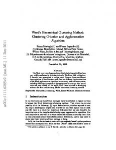
(a) F = D/(di+dj) < 1
D < (di+dj)
(b) F = D/(di+dj) = 1 (c) F = D/(di+dj) > 1
D = (di+dj) D > (di+dj)
Fig. 1. Illustrations of filling factors computed according to [9]. In the three situations, the left and right configurations have similar filling factors, while the real filling is significantly different.
II. OBJECT-ORIENTED HIERARCHICAL REPRESENTATION A new hierarchical clustering algorithm for generating an inter-object representation from a set of objects contained in a scene is described. The algorithm is an iterative process that builds each level of the hierarchy by grouping the bounding spheres contained at the previous level. The process stops when a single bounding sphere is left. Three stages are subsequently applied at every level. In the first stage, a fully-connected adjacency graph that keeps the cost of grouping the different pairs of spheres present at the current level is built. In the second stage, the minimum spanning tree (MST) of that graph is computed. In the last stage, the edges of the MST are clustered based on their cost. The edges that belong to the cluster corresponding to the lowest cost denote pairs of spheres that are candidate to group. Those spheres are finally grouped (substituted for their smallest bounding sphere) if a merging criterion is satisfied. As a result, a new level of the hierarchy is generated, which contains the new spheres and the ones that could not been grouped. The same three stages are then applied to the next level. These stages are further described below.
(b)
every graph’s edge, since, in the end, it will determine the order in which spheres will be grouped. This function must be properly defined in order to achieve a well balanced and spatially coherent hierarchy. Previous schemes propose cost functions based on the attraction force between two objects [10] or on heuristics that favor that objects of similar size are merged, beginning with those with the smallest volume [9]. Alternatively, we define a cost function that depends on both the size of the smallest sphere that contains the spheres to be grouped, and a filling factor defined as the ratio between both the volume occupied by those spheres and the volume of their smallest bounding sphere. In other words, the proposed filling factor is a measure of empty space, as opposed to [9], where the filling factor is defined as the ratio between the diameter of the bounding sphere (D) and the sum of diameters of the merged spheres (di+dj). Fig. 1 illustrates some situations where the filling factor F proposed in [9] is not a good indication of the real filling. For example, the smallest bounding sphere in Fig. 1(b) [right grouping] should be the one with the best filling factor. However, both bounding spheres have the same factor (F=1). The same occurs in Fig. 1(a) and Fig. 1(c): the configurations on the right have better filling than the ones on the left, while their filling factors are approximately the same. Another advantage of the proposed technique over the one defined in [10] and [9] is that the value of the computed filling factor is preserved in the hierarchy as an indicator for further grouping. Thus, every sphere S i is associated with a filling factor F i . The bounding spheres corresponding to the original objects of the scene have a filling factor equal to one. In turn, when two spheres S i and S j are grouped, the filling factor of their minimum bounding sphere S ij is formulated as: F ij = ( F i Vol i + F j Vol j – Vol overlap ) ⁄ Vol ij
(1)
where Vol i , Vol j and Vol ij are the volumes of S i , S j and S ij respectively, and Vol overlap is the volume defined by the overlap (intersection) between S i and S j , which is computed as the union of the volumes of two spherical caps (Fig.
5288
(G,D) (A,C) (D,E) (C,B) (F,H) (B,F) (D,F) 3.7
hc
E0
rc
4
4.1
E1
E2
4.8
7.1
7.3
.............................
10.3 Er
Nodes Costs Edges
List of MST edges in ascending order of cost ξ = {(G,D), (A,C), (D,E), (C,B)}
d
Fig. 3. List of the MST’s edges sorted in ascending order of cost (the cluster corresponding to the lowest costs is shadowed).
ri
rj
rc
function is defined as: 3
ζ ij = r ij ⁄ F ij hci
hcj
Fig. 2. (top) Portion of a spherical cap cut off by a plane. (bottom) Illustration of two spherical caps defining the volume of overlap (intersection) between two spheres.
2): Vol overlap = F i V ci + F j V cj . The volume of a spherical cap is defined as: π 2 2 V ci = --- ( 3r c + h ci )h ci 6
(2)
where rc is the radius of the cap’s base and hci is the cap’s height, Fig. 2(top). The radius of the cap (circle of intersection between the two overlapped spheres) and the heights of the two caps depend on the distance d between the centers of the two spheres and their size. If the cap corresponding to the sphere of radius ri has height hci, and the cap of the sphere of radius rj has height hcj, Fig. 2(bottom), the radius of the common circle rc is computed as follows: 2
2
2
2
( ( r i + rj ) – d ) ( d – ( ri – rj ) ) r c = --------------------------------------------------------------------------------2d
(3)
hci and hcj are defined as: 2
h ci
2
r j – ( ri – d ) = -------------------------------2d
2
h cj
2
r i – ( rj – d ) = -------------------------------2d
(4)
Vci and Vcj are respectively computed from (hci, rc) and (hcj, rc) by applying (2). Besides taking into account the previous filling factor, the proposed cost function also considers the size of the bounding spheres in order to enforce a monotonous growth of the groups of spheres. Let r ij be the radius of the smallest bounding sphere, S ij , which contains S i and S j . The proposed cost
(5)
with F ij computed according to (1). The smaller and closer two spheres are, the lower their grouping cost will be. Intuitively, spheres with small merging costs should tend to be grouped together as they would denote close objects in the scene. This process is intended to create a hierarchy in which leaves, which represent the original objects, are progressively grouped until the scene’s bounding sphere at the root of the tree is obtained. The proposed strategy favors that small clusters are created first, as well as a progressive growth of the radius of the resulting spheres when the hierarchy’s level is reduced. By using a more realistic filling factor, objects are grouped in a more intuitive way than in [9]. If several spheres { S a, S b, …, S z } are to be grouped together, the filling factor and cost function associated with their smallest bounding sphere S ab…z are respectively computed by applying recursively: F ab…z = F { ab… }z and ζ ab…z = ζ { ab… }z . B. Minimum Spanning Tree Generation Once an adjacency graph has been created, the next objective is the computation of its minimum spanning tree. The minimum spanning tree (MST) of a graph G is the acyclic subgraph of G that contains all the nodes of G and such that the sum of the grouping costs (5) associated with its edges is minimum. The MST of a graph with M edges and N nodes can be efficiently computed in O ( M log N ) by applying Kruskal’s algorithm [11]. C. Object Clustering and New Level Generation The outcome of the previous stage is a list of edges that constitute the MST of G. The current stage clusters those edges based on their associated grouping costs (5) and determines the cluster corresponding to the lowest cost. A new level of the hierarchy is then created. It contains new spheres obtained by merging the nodes linked by edges that belong to that lowest cost cluster, as well as the remaining spheres that cannot be merged. In the majority of general purpose clustering algorithms
5289
proposed in the literature, the desired number of clusters must be specified in advance. Since this information is not available in the problem at hand, X-means [12], a generalization of K-means that estimates the number of generated clusters, has been utilized for clustering the edges of the MST according to their grouping cost. Let ξ = { E 0, E 1, …, E k, …E m } be the set of edges contained in the cluster generated by X-means corresponding to the lowest grouping cost. Those edges are sorted in ascending order of cost and are considered in sequence, starting with the one of lowest cost, E0 . An edge E k links two spheres S i and S j at the current level λ of the hierarchy. If S i and S j have not already been merged when previous edges in ξ were considered, E k denotes a valid merging, and the smallest sphere S ij that encloses S i and S j is generated as a new object. This sphere is associated with a filling factor F ij (1). On the contrary, if S i , S j or both have already been merged with other spheres when previous edges in ξ were considered, giving rise to new bounding spheres, the latter referred to as S I and/or S J , E k will only be accepted as a valid merging if its cost, ζ , belongs to the cluster ξ (e.g. assuming both spheres have been previously merged ζ IJ ≤ ζ m , where m is the edge with the highest cost in the computed cluster). This acceptance criterion is applied in order to handle situations where a set of spheres are equally distributed over the scene, for example, placed at the same distance along a row. If all the edges in ξ were accepted in such a case, an unbalanced tree would be generated. After processing all the edges contained in ξ , a new level λ – 1 is generated. This new level only contains the merged spheres generated after processing the edges belonging to ξ , as described above, and those spheres not merged during that process. Both the new and old spheres will become the nodes of the adjacency graph generated at level λ – 1 , and the whole process will be iterated. The previous process is illustrated with a simple example based on the edge list shown in Fig. 3. Capital letters identify bounding spheres present at that level. From that list, edges that have a similar cost { ( G, D ), ( A, C ), ( D, E ), ( C, B ) } are clustered together, defining the set ξ . The first considered edge is the one joining nodes G and D, as its cost is the lowest (3.7). Nodes G and D have not been previously considered. Therefore, a first group, GD, is formed and associated with the smallest sphere that encloses both G and D and a filling factor FGD. The second edge in ascending order is the one joining nodes A and C (cost 4). Again, none of them have been previously considered. Thus, a new group, AC, is created and associated with the smallest sphere that embodies A and C, and a filling factor FAC. The third edge is the one joining nodes D and E (cost 4.1). Since D belongs to an already merged group (GD), the feasibility of GDE is analyzed. In order to do so, the filling factor of the new candidate group, FGDE, is computed and the corresponding cost, ζ GDE , compared to ζ CB , which is the highest cost in the cluster. If ζ GDE ≤ ζ CB , GDE is accepted as a new group and the smallest sphere that contains G, D, and E is cre-
{AC},{GDE},B,F,H AC A
GDE C
G
D
E
Level0
B
F
H
B
F
H Level2
Level1
Fig. 4. Final hierarchical representation in the example.
ated and assigned its filling factor FGDE. If the merging is not accepted, edge D-E is discarded. The final edge in ξ is the one joining nodes C and B (weight 4.8). Similarly to before, since C belongs to an already generated group, AC, the new candidate cluster ABC is considered. If we assume in this case that ζ ABC > ζ CB , edge C-B is discarded and so is group ABC. In the end, the two new groups {AC, GDE} and the nodes that could not be merged {B, F, H} constitute the objects (spheres) that will be processed at the next level of the hierarchy, in which the process starts over from the adjacency graph generation stage (section 2.1). Fig. 4 shows an illustration of the final hierarchical structure obtained after applying the proposed algorithm. III. EXPERIMENTAL RESULTS The proposed technique has been applied to synthetic 3D scenes of increasing complexity. CPU times have been measured on a 650 MHz Pentium III PC. Fig. 5(top) shows a scene with 24 objects. Each object is represented by its bounding sphere. In this example, a hierarchical representation of 8 levels was computed in 0.01 sec. Fig. 5(bottom) presents different levels of the hierarchy. Dark solid spheres correspond to objects merged at the previous level. Dark wireframe spheres represent objects that will be merged at the current level. Finally, light wireframe spheres represent non-merged objects at that level. The levels are represented at different scales. Comparisons with both [9] and [10] showed that although all the algorithms produce comparable hierarchical representations when scenes containing few objects were considered, the hierarchical representations, as well as the CPU times, are considerable better with the proposed algorithm when complex and large scenes were considered. Moreover, these advantages are emphasized when a particular scene containing equally-sized objects, regularly distributed over the space, is considered; neither [9] nor [10] can appropriately handle this situation. Advantages in front of [9] mainly lie in the definition of a more realistic filling factor measure along with a more efficient cost updating strategy (the cost between all objects does not have to be computed after every new object generation stage, but after every new level generation stage). The pro-
5290
P2
P1 P2
Level 8 (24 objects)
Level 6 (10 objects)
P1 Fig. 6. (top) Third level of an object-oriented representation of a scene defined by 21 objects (points P1 and P2 were randomly placed over opposite faces of the bounding box). (bottom) Fourth level of the corresponding scene-oriented hierarchy (octree). Level 5 (9 objects)
Level 2 (3objects)
Level 3 (4 objects)
Level 0 (1 object)
posed algorithm also presents advantages in front of [10]. These advantages can be appreciated in the structure of the resulting hierarchical representation, while the CPU times of both techniques are quite similar. The proposed technique has also been compared to the well-known octrees from the point of view of a practical task consisting of determining the object at minimum distance from a given straight segment (see Fig. 6). The comparison has been carried out over scenes defined by 50, 100, 150, 200..., 500 randomly placed spheres of random size. 500 random segments were tested over each scene. As an example, Table I presents the number of clusters (objects) obtained at every level of the hierarchy for the case of 100 spheres. A total of 21 levels were generated in 0.07 sec. In order to determine the closest object to a segment, a search algorithm explores the given hierarchical structure (octree or proposed technique) starting from its root. At every iteration, those spheres intersected by the given segment are removed and the distances from the segment to their children are computed.
Fig. 5. (top) Original scene consisting of 24 objects. (bottom) Levels of the computed hierarchical representation (dark solid spheres correspond to objects merged at the previous level; objects merged at the current level are represented in dark wireframe).
This recursive process is applied until either no sphere is intersected by the segment or all the intersected spheres are leaves of the tree. A comparative study has been carried out over scenes containing different amounts of objects.
5291
TABLE I HIERARCHICAL REPRESENTATION OF A SCENE DEFINED BY 100 OBJECTS RANDOMLY PLACED WITH A RANDOM SIZE.
Level
0
1
2
3
4
5
6
7
8
9
10 11 12 13 14 15 16 17 18 19 20 21
Objects
1
3
4
7
8
11 15 18 20 21 25 27 29 30 32 37 47 49 59 68 78 100 Hence, further work will consist of the study of other bounding volumes, such as ellipsoids [13]. The utilization of these new geometric primitives involves the definition of new cost functions. In addition, practical applications of the proposed 3D hierarchical representations as a means to speed-up path planning or collision avoidance algorithms will be developed.
Iterations
Octree Proposed technique
REFERENCES
Objects Fig. 7. Average number of iterations necessary to find the nearest object to 500 different random segments, by using both the hierarchies generated with the proposed technique and octrees. The scenes contain 50, 100, 150, .... up to 500 objects.
The octree is recursively expanded until its leaves are one third the size of the smallest input sphere. A bar diagram showing an average number of iterations, computed for the 500 random vectors, necessary to determine the nearest object corresponding to both octrees and the hierarchies generated with the proposed techniques is presented in Fig. 7. Fig. 7 shows that the amount of iterations required to find the nearest object to a segment is at least twice and a half times lower with the proposed object-oriented technique than with octrees in all cases. IV. CONCLUSIONS A new technique for generating a hierarchical representation of the objects contained in a 3D scene has been presented. The proposed technique consists of three stages. The first stage computes the cost of grouping all the pairs of objects in the scene and generates an adjacency graph with those costs. In the second stage, the minimum spanning tree (MST) of that graph is generated. In the last stage, an efficient clustering algorithm is used to select the set of objects to be merged at that level. These stages are applied until a level with a single object is reached. Spheres are the most common bounding volume due to the simplicity both to represent them and to detect intersection among them. However, not every object contained in a given scene can be accurately represented by a single sphere.
[1]
K. Prevas, C. Unsal, M. Efe and P. Khosla, “A Hierarchical Motion Planning Strategy for a Uniform Self-Reconfigurable Modular Robotic System”, IEEE Int. Conf. on Robotics and Automation, Washington, USA, May 2002.
[2]
J. Fernández-Madrigal and J. González, “Hierarchical Graph Search for Mobile Robot Path Planning”, IEEE Int. Conf. on Robotics and Automation, Leuven, Belgium, May 1998.
[3]
S. Dandamudi, P. Cheng, “A Hierarchical Task Queue Organization for Shared-Memory Multiprocessor Systems”, IEEE Transactions on Parallel and Distributed Systems, vol. 6, no. 1, January 1995, pp. 1-16.
[4]
H. Cheng and Y. Sun, “A Hierarchical Approach to Color Image Segmentation Using Homogeneity”, IEEE Trans. on Image Processing, vol. 9, no. 12, December 2000.
[5]
J. Huerta, M. Chover, R. Quiros, R. Vivo and J. Ribelles, “Binary Space Partitioning Trees: a Multiresolution Approach”, IEEE Int. Conf. on Information Visualization, London, UK, August 1997.
[6]
P. Payeur, D. Laurendeau and C. Gosselin, “Range Data Merging for Probabilistic Octree Modeling of 3-D Workspaces”, IEEE Int. Conf. on Robotics and Automation, Leuven, Belgium, May 1998.
[7]
P. Brunet and I. Navazo, “Solid Representation and Operation Using Extended Octrees”, ACM Transactions on Graphics, 9(2), 170-197, April 1990.
[8]
J. Fernández-Madrigal and J. González, “Multihierarchical Graph Search”, IEEE Trans. on Pattern Analysis and Machine Intelligence, vol. 24, no. 1, January 2002.
[9]
P. Xavier, “A Generic Algorithm for Constructing Hierarchical Representations of Geometric Objects”, IEEE Int. Conf. on Robotics and Automation, Minneapolis, Minnesota, April 1996, 3644-3651.
[10] M.A. Garcia, A. Sappa and L. Basañez, “Efficient Generation of Object Hierarchies from 3D Scenes”, IEEE Int. Conf. on Robotics and Automation, Detroit, Michigan, USA, 1359-1364, May 1999. [11] K. Rosen, Discrete Mathematics and its Applications, McGraw-Hill, Inc., New York, second edition, 1990. [12] D. Pelleg and A. Moore, “X-means: Extending K-means with Efficient Estimation of the Number of Clusters”, Seventeenth Int. Conf. on Machine Learning, San Francisco, USA, 2000. [13] E. Rimon and S. Boyd, Obstacle Collision Detection Using Best Ellipsoid Fit, J. of Intelligent and Robotic Systems, vol. 18, No. 2, pp. 105-126, February
5292