RAM, 256-MB flash memory), an Atheros AR5213A chipset mini PCI card, a Fidelity Comtech bidirectional amplifier. Fig. 3. CU Air Vehicle Fleet and Support ...
Hierarchical Distributed Control for Search and Tracking by Heterogeneous Aerial Robot Networks Jack Elston
Eric W. Frew
Aerospace Engineering Sciences Department University of Colorado Boulder, Colorado 80309
Aerospace Engineering Sciences Department University of Colorado Boulder, Colorado 80309
Abstract—This paper presents a hierarchical control architecture that enables cooperative surveillance by a heterogeneous aerial robot network comprised of mothership unmanned aircraft and daughtership micro air vehicles. Combining the endurance, range, and processing capabilities of the motherships with the stealth, flexibility, and maneuverability of swarms of daughterships enables robust control of aerial robot networks conducting collaborative operations. The hierarchical control structure decomposes the system into components that take advantage of the abilities of the different types of vehicles. The motherships act as distributed databases, fusion centers, negotiation agents, and task supervisors while daughtership control is achieved using cooperative vector field tracking. This paper describes the overall arcitecture and then focuses on the assignment and tracking algorithms used once subteams of daughtership vehicles have been deployed. A summary of the communication, command, and control structure of a heterogeneous unmanned aircraft system is also given in this paper along with hardware-in-the-loop and software simulation results verifying several components of the distributed control architecture.
I. I NTRODUCTION Heterogeneous aerial robotic networks that combine the long endurance, range, and processing capabilities of mothership unmanned aircraft with the stealth, flexibility, and maneuverability of swarms of daughtership micro air vehicles (MAVs) are ideal for cooperative search, acquisition, and tracking (CSAT) in urban environments and rough terrain [1] [2]. Micro air vehicles offer greater flexibility, maneuverability, and stealth compared to larger unmanned aircraft (UA) systems. However, a fundamental drawback of MAV systems is their short range, low endurance, and small payload capacity. Current MAV systems typically have limited operation of 1-2 hours maximum flight time. While this amount of flight time is adequate for ”over the hill” surveillance, it limits the use of swarms to small-scale engagements. Deployment from larger mothership vehicles enables the insertion of MAV swarms into environments of extended size and is the ideal strategy for CSAT applications. In addition to extending the footprint of operation of MAV teams, the mothership/daughtership (MS/DS) concept increases system performance by combining the complementary capabilities of the MS and DS vehicles. The payload capabilities of MAV platforms fundamentally limit the amount of sensor information, communication, and processing that
can be achieved by these systems. In constrast, the size of the mothership vehicles allows them to carry systems that can communicate over larger distances and process more information at higher rates than the DS vehicles. Thus, coordinated control of micro air vehicle teams deployed in MS/DS architectures exploits the communication and processing capabilities of the mothership vehicles to minimize the amount of communication, estimation, planning, and coordination performed by the DS vehicles. This paper describes a hierarchical control architecture that enables cooperative search, acquisition, and tracking by a heterogeneous aerial robot network operating in a mothership/daughtership configuration. A high-level description of the control architecture is provided that highlights complementary aspects of the mothership and daughtership vehicles. Details are provided for assignment and cooperative tracking algorithms utilized by daughtership sub-teams once they have been deployed. Additionally, this paper describes the communication, command, and control structure of a heterogeneous aerial robot network developed to validate the MS/DS concept of operations. Software simulations are provided to demonstrate aspects of the control structure while hardware-in-the-loop simulations highlight components of the experimental platform. II. H IERARCHICAL C OOPERATIVE S EARCH , ACQUISITION AND T RACKING A RCHITECTURE Consider a heterogeneous unmanned aircraft system denoted by the set H consisting of two main types of aircraft comprising the (disjoint) sets M ⊂ H of mothersip vehicles and D ⊂ H of daughtership vehicles. Let mi ∈ M, i = [1, · · · , nm ] denote the ith mothership vehicle in the set M . Each mothership is assigned a subset Di ⊆ D of daughtership vehicles to which it communicates where di,j ∈ Di , j = [1, · · · , ni ] is the jth vehicle in Di . We assume that each daughtership communicates with one and only one mothership vehicle and each mothership mi acts as the gateway to the subnetwork defined by the vehicles in Di . Communication between the mothership mi and daughterships di,j occurs directly or over a multi-hop connection. This work assumes UA are equipped with a low-level flight control system that provides roll, pitch, and yaw stability of the aircraft as well as velocity tracking and altitude-hold
functions. For aircraft guidance, the flight control system accepts speed, climb rate, and turn rate commands. Using this command structure, the model presented to the guidance layer of the ith UA is a kinematic model: x˙ i u1,i cos(ψi ) + Wx vmin ≤ u1,i ≤ vmax y˙ i u1,i sin(ψi ) + Wy ψ˙ i = u2,i |u2,i | ≤ ωmax u3,i |u3,1 | ≤ hmax h˙ i (1) where xi = [x, y, h] ∈ rd , the vector field points to the loiter circle center and the field veers away when approaching the circle to smoothly entrain the motion into a left turn loiter. Phase coordination of multiple robots around the desired contour is produced by a second control law which adjusts the speed of the vehicles (within limits). For two cooperating robots with phase angles θ1 and θ2 defined relative to the instantaneous target location, the speed commands u1,1 = k1 (θ2 − θ1 − θD ) + v0 u1,2 = −k1 (θ2 − θ1 − θD ) + v0
(4)
drive the relative angle θ2 − θ1 to the desired phase offset θD [4]. An important characteristic of this algorithm is that only a single additional variable, θi , needs to be communicated between vehicles in order to enable coordination. When multiple DS are tracking an uncertain moving target, the covariance matrix P of the estimate position error can be used to define an elliptical orbit pattern about the target. In order to insure that the desired stand-off radius rd is maintained we first take the singular value decomposition of the matrix � � √ σ1 0 S = nσ P = U · ·V (5) 0 σ2 and then create the new matrix � σ1 + rdes M=U· 0
0 σ2 + rdes
Since the goal of the system is to track each target to within the prescribed bounds, a mode switch occurs once ρt ≤ ρ∗min . III. H ETEROGENEOUS A ERIAL ROBOT N ETWORK A RCHITECTURE The implementation of the robot network, referred to as the Heterogeneous Unmanned Aircraft System (HUAS), consists of multiple small Ares UA and miniature CU MAVs connected through a multi-tier airborne network. The system is designed so that each UA can operate autonomously and recognize the capabilities of other friendlies in the area in order to self-organize cooperative groups. Should input to the system from an remote operator be desired, stations located on site (within communication range of the meshed network) or off-site can at any time be added to the network. Command and control data from outside the deployed mobile ad-hoc network is sent to a network gateway which provides address translation and transmits the data to the vehicles. Using peerto-peer routing protocols data hops through the network to the intended source, taking multiple hops between heterogeneous nodes as needed. Telemetry and payload sensor data are provided in a publish-subscribe manner, and can be subscribed to by any network participant. The architecture of the HUAS was designed using a bottom-up layered approach (Figure 2). This approach allows for the design of UA and supporting systems to reflect and enhance design decisions made at the network layer. Given that the success of the HUAS system is based heavily on networked communications, this approach guarantees that the requirements of the high level cooperative algorithms can be met by the underlying architecture. Design was conducted by constructing and fully characterizing lower levels before making subsequent design decisions at higher layers. The design layers are: the physical and transport layer, the network protocol and data routing layer, the censor, communication, and control fusion layer, the application layer networking, and the cooperative control layer.
� ·V
(6)
To loiter about the new elliptical pattern we define the new vector field gP (p) = M · g(M −1 · p). The trajectory guidance layer is currently made up of the several modes derived from the vector field algorithms. The LOITER, FOLLOW, and PROTECT modes are cooperative tracking controllers for stationary targets (waypoints), moving targets, and friendly targets, respectively. The SEARCH mode represents the default action of the DS vehicle based on the last commanded location from the assignment layer.
Fig. 2.
Effective Layers used for the CU HUAS Design.
A. Physical and Transport Layer Two main aircraft were developed for the HUAS, however the network has been extended to allow for participation by most of the UA in the CU fleet (Figure 3). The first vehicle is the CU Micro Air Vehicle (MAV), which is based
on a modified commercial foam kit with electric propulsion that has an empty weight of approximately 20 oz. At small vehicle scales, avionics mass is a significant limiting factor of vehicle range and endurance. This was minimized by a flight control system which uses only one rate gyro for attitude control, an extremely compact GPS receiver for positioning, and a MEMS pressure sensor for altitude. Two micro-servos on elevons provide the only control surfaces. Details of the avionics system for the MAVS can be found at [6]. MAV networking is provided by the Maxstream XBEE Pro Zigbee radio using the IEEE 802.15.4 protocol. These devices were chosen for their lower power, small size, relatively long transmission range (verified to 2 mi), serial interface compatibility with avionics processors, and packet interface. The radio provides simple point to point or networked functionality, with newer models implementing AODV routing protocols in hardware. Power consumption of the radio is relatively modest compared with powering the aircraft’s electric propulsion system. The second UA is the Ares aircraft which is constructed entirely at CU Boulder. The airframe of the Ares aircraft is based on the layout of the Senior Telemaster, a popular RC model. Custom modifications include an expanded fuselage to accommodate a payload section and conversion from a tail-dragger configuration to one with tricycle gear. The monocoque fuselage, wings, main gear, and horizontal tail are made of a carbon composite laid over carbon-composite laminated plywood bulkheads and ribs. The Ares is powered by a 5-hp, two-stroke engine and has an additional payload capacity of 10 pounds. With a full 1-gal tank, the endurance is estimated to exceed 3 hr. The Piccolo Plus autopilot is used for autonomous flight, with manually controlled takeoff and landing. The mobile ad-hoc network connecting the Ares UA to one another and dispersed operators is based on the IEEE 802.11b (WiFi) standard, chosen primarily for COTS compatibility. Network software combined with the communication hardware is denoted as the mesh network radio (MNR). The MNR hardware components are a Soekris Engineering Model 4511 single board computer (100-MHz 486 processor, 64-MB RAM, 256-MB flash memory), an Atheros AR5213A chipset mini PCI card, a Fidelity Comtech bidirectional amplifier
with up to 1-W output, and a Garmin Model 35-HVS GPS receiver. The core of each MNR node is identical, only the packaging differs depending on whether the MNR is mounted at a fixed ground site, on a ground vehicle, or in a UA. Flight test results have demonstrated that under typical conditions this system can achieve 1.0 Mbps throughput at a distance up to 4km from the UA to ground, but have also demonstrated drawbacks to using 802.11b in highly dynamic environments [7]. B. Network Protocol and Data Routing The network protocol and data routing layer was built on top of the COTS wireless networking standards. Two distinct network tiers, a high-level tier supported by the Ares UA based on IEEE 802.11b (WiFi) and a low-level tier supported by the MAVs using IEEE 802.15.4 (Zigbee), were developed and combined into a single multi-tiered network. The highlevel tier is based on the Ad-hoc UA Ground Network (AUGNet) [7] and the low-level tier is based on the CU MAV Sensor Flock concept [8]. The AUGNet system is a wireless multi-hop network designed for highly mobile environments. It includes the ability to collect various network performance metrics and log them to remote servers in real time. The main components of the system include: custom made mesh network radios; network monitoring software and a database that can be accessed during flight experiments from the Internet; routing software using the Click modular router to implement dynamic source routing (DSR); and the CU Ares aircraft. TCP and UDP transport protocols are supported, along with a modified version of the UDP protocol which provides reliable message delivery using node-by-node custody transfer[7]. The AUGNet system has been characterized through various experiments investigating the impact of disconnected groups, air to ground communication, and extended air-to-air networking [7]. Meshed networked communication between MAVs and from the MAVs to the Ares UA is achieved using a custom implementation of the IEEE 802.15.4 protocol. This network stack sits atop the PHY and MAC network layers provided by the IEEE 802.15.4 standard. It consists of a number of additional layers that provide high-mobility ad-hoc networking capabilities, including security functions, mesh networking, and multi-modal (i.e. high data rate, low data rate, and sleep mode) operation. In particular, current networking research developments are directed toward comparison of standard ad-hoc approaches, such as AODV, with new MAV-tailored schemes that exploit asymmetry in the MAV-SAV link capabilities such as high power one-hop SAV-MAV and lowpower multi-hop MAV-MAV and MAV-SAV links. C. Sensor, Communication, and Control Fusion
Fig. 3. CU Air Vehicle Fleet and Support Trailer. Vehicles from Left to Right, Top to Bottom are: Ares SAV, CU MAV, Velocity SAV, NexSTAR SAV, Support Trailer, and the MLB Bat UAS.
The next functional layer in the HUAS architecture utilizes the multi-tiered network to create a system that can fuse sensor, communication, and control information into individual intelligent vehicle platforms. The core of this layer are a
networked communication, command, and control system; onboard component integration through interface nodes; and flight management for individual vehicles [9]. Onboard flight management of the Ares aircraft is achieved through an embedded architecture that integrates custom and COTS components using intelligent interface nodes. Modularity and module independence are achieved by using high level bus protocols between each interface node. The flight mangement system (FMS) consists of the Communication subsystem, the Autonomous Flight Control Module, the Computational Module, and a collection of sensors in the Sensor Modules subsystem. The FMS is monitored and controlled from Remote Monitor Stations using the VirtualCockpit through AUGNet. D. Application Layer Networking The application layer networking provides the mechanism for service discovery, data stream subscription, and command issuance over the network. This software enables using more than one groundstation; communications with any node without prior knowledge of IP addresses; interaction with the UA from outside of the adhoc network; and communication between both MAVs and SAVs over the multiple, heterogeneous sub-networks. Application layer networking is implemented entirely in software and uses an object-oriented approach to define components. The highest level object is the Network Appliance. The Network Appliance is composed of one to many Interface objects, each providing a connection between individual inputs and outputs (ad-hoc network, zig-bee network, www interface, slip interface) and the central Data Distribution object. The Data Distribution object intelligently forwards incoming data to one or many of the Interface objects. Each network appliance also includes a Data Logging object, a Capabilities Manager object (which was added for the service discovery protocol), and a list of known clients. The client list keeps track of all devices the Network Appliance has communicated with and stores pertinent information such as last communication time, last known location, text name or description (e.g ”Ares 2”), address, capabilities, etc. Each interface object, when invoked, registers the capabilities it enables with the Capabilities manager object. It is in this manner that the network appliance object is aware of its various capabilities (autonomous flight, gateway to external networks, etc.). Associated with each capability are data streams that other clients might subscribe to, or commands that can be accepted by the particular interface. This information is broadcast over the network at a fixed interval providing for service discovery to occur, and simple status of each network node to be maintained. To define services, a description language was needed. Most of the existing languages require XML (which would require too much overhead on the smaller platforms), have too extensive of a library, or do not allow for the proper definition of services. In the current implementation, each UA subsystem is given a 4 bit unique id. Available streams
and accepted commands for the subsystem are defined by two 8 bit bit fields. This 20 bit representation of a set of subsystem capabilities provides enough flexibility to define all of the current subsystems and allows for significant future expansion. Furthermore, by using the combination of the 4 bit subsystem id, and the 4 bit location of the specific accepted command or data stream identifier bit as the header for internal packets, many interesting networking capabilities are enabled such as content-based forwarding. E. Cooperative Control Layer The final layer in the HUAS network architecture consists of either semi-autonomous (i.e. operator in the loop), autonomous, or cooperative control algorithms. These algorithms utilize the application layer networking software to coordinate aircraft and provide sensor and telemetry data to subscribers, including other aircraft and multiple dispersed users. It is at this layer that the CSAT algorithm is implemented. IV. R ESULTS A. HWIL MAV Robot Control In order to facilitate development and testing of the HUAS systems, a hardware-in-the-loop (HWIL) simulation capability has been created. This laboratory environment uses all the hardware and software components of the full HUAS system with the exception of the autopilot sensor measurements. Instead, modified sensor measurements are given as inputs to the navigation subsystem from flight simulator software provided with the PiccoloPlus or from internal simulation components of the CU MAVs. The navigation subsystems of each autopilot output the control surface commands to software components that simulate the aircraft flight. The result of the HWIL system is that the UA ”thinks” it is flying while sitting on the lab bench, including deflection of the aerodynamic control surfaces and actuation of engine throttle. In this way, system interactions can be tested under simulated flight conditions; the multi-tiered network can be validated under benign conditions; and coordination of multiple heterogeneous vehicles can be demonstrated inside the laboratory. Using the HWIL setup several simulations have been conducted to demonstrate various components of the CSAT algorithm. Cooperative tracking between 3 Ares UA of a single target has been demonstrated HWIL [5]. This simulation did not require any user input or a ground station. Each UA used the telemetry stream from the other two UA to maintain phasing while orbiting the target. Following sucessful simuluation of SAV ground vehicle tracking, this software was simplfied and broken apart to provide tracking functionality for the MAVs. The gateway to the MAV network (whether a ground station or Ares MS) maintains the coordination and assignment functionality, while the MAVs implement the functionality required to allow control of the UA via inputs defined in Equation 1.
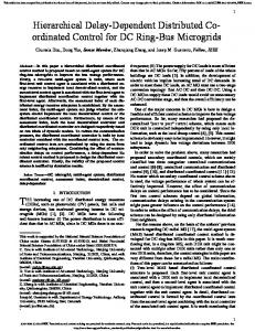
Figure 4 shows the results from the HWIL simulation of two MAVs assigned to track a moving ground node. The trajectory of the target node is in black, and the trajectories of the two MAVs are in green and red. The assignment and 40.134 coordination in this case took place on a grounstation laptop, but could have just as easily been performed by a Soekris 40.133 SBC in an Ares SAV. 40.132 MNR0 Motion 40.131
Latitude
40.13
40.129
40.128
40.127
40.126
Fig. 4.
HWIL showing two MAVs tracking a moving ground target.
40.125
Given the limited amount of available hardware, HWIL 40.124 simulations involving more than a handful of aircraft was −105.244simulations −105.242 −105.24 −105.238 −105.236 not possible.−105.246 Software were therefore required Longitude to demonstrate CSAT using a larger number of vehicles. An simulation was run using 9 aerial robots searching an area that contains 4 moving targets. The aerial robots move with a nominal airspeed of v0 = 20 m/s, have a maximum turn rate ωmax = 0.2 rad/sec, and are allowed deviations of ∆v = 5 m/s for coordination. The environment is 5000 meters wide and 8000 meters long. Initial positions of the 9 aircraft and 4 targets are randomly selected. Ground targets move with constant velocity with speed randomly chosen on the interval [4, 10] and random initial headings. Targets change direction only upon reaching the boundary of the environment. 200
ρ [m]
150
100
50
0
100
200
300
400 Time [sec]
500
600
700
800
Fig. 5. Square root of the maximum singular value of the position error covariance matrix versus time.
The task assignment algorithm attempts to keep the position error ρk between 20 and 50 meters. Each active target is assigned to two robots who track the target until ρ ≤ 20m and all remaining robots are assigned to search. The approximate average robot p and target error velocities are set to v = 0.8v0 and ρ˙ = 2 ρ(Pv ), respectively. Centralized task assignment is performed using binary integer programming and the coverage map described in [3]. Figure 5 shows a plot of ρ for each target as a function of time. The dashed lines denote the upper and lower bounds
of the desired position error. The CSAT algorithm is able to provide significant coverage of the environment while also keeping the target uncertainty below the specified bound most of the time (Fig. 5). Since the approximations v and ρ˙ were set heuristically, they are not always conservative and the target uncertainty occasionally grows above the given limit. V. C ONCLUSION This paper presented a hierarchical control architecture that enables cooperative surveillance by a heterogeneous aerial robot network comprised of mothership unmanned aircraft and daughtership micro air vehicles. A new integrated search and tracking assignment algorithm is used for task assignment by the mothership vehicles while daughtership control uses a simple guidance vector field motion primitive for loiter and tracking tasks. A heterogeneous unmanned aircraft system is described that will be used to verify the control approach described here. Current work focuses on demonstrating the entire CSAT architecture using the hardware-in-the-loop simulation capability of the experimental platform. Implementation of the DS task assignment algorithm is currently being done. Future work will address distributed negotiation between MS vehicles to claim tasks that are then assigned to their DS vehicles. Also, experimental validation of all components of the CSAT system are underway. R EFERENCES [1] D. Gross, S. Rasmussen, P. Chandler, and G. Feitshans, “Cooperative operations in urban terrain (counter),” in Defense Transformation and Network-Centric Systems. Edited by Suresh, Raja. Proceedings of the SPIE, Volume 6249., 2006. [2] D. Ratner and P. J. McKerrow, “Aerial tethered robotics system with hovering-hopping agents for security and rescue operations,” in Proc. of AUVSI’2006 INTL Conference on Unmanned Systems North America, Orlando, Canada, Aug. 2006. [3] E. W. Frew and J. Elston, “Target assignment for integrated search and tracking by active robot networks,” in Proceedings of the 2008 IEEE International Conference on Robotics and Automation, Pasadena, CA, 2008. [4] E. W. Frew, “Cooperative stand-off tracking of uncertain moving targets using active robot networks,” in Proceedings of the 2007 IEEE International Conference on Robotics and Automation, Rome, Italy, May 2007. [5] J. Elston and E. W. Frew, “Net-centric cooperative tracking of moving targets,” in AIAA Infotech@Aerospace, Rohnert Park, CA, May 2007. [6] W. Pisano, D. Lawrence, and P. Gray, “Autonomous uav control using a 3-sensor autopilot,” in AIAA Infotech@Aerospace 2007 Conference and Exhibit, May 7-10 2007. [7] T. Brown, B. Argrow, E. Frew, C. Dixon, D. Henkel, J. Elston, and H. Gates, “Experiments using small unmanned aircraft to augment a mobile ad hoc network,” in Emerging Technologies in Wireless LANs: Theory, Design, and Deployment, B. Bing, Ed., 2007, ch. 28, pp. 123– 145. [8] D. Lawrence, K. Mohseni, and R. Han, “Information energy for sensorreactive uav flock control,” in AIAA 3rd Unmanned Unlimited Technical Conference, Workshop, and Exhibit, Sept. 20 - 23 2004. [9] J. Elston, E. W. Frew, and B. Argrow, “Networked uav communication, command, and control,” in AIAA Guidance, Navigation, and Control Conference, Keystone, CO, August 2006.