together with an application oriented view of specification as a practical tool for ... implementation or programming language, especially if performance is a major ...
Proceedings of the 35th Hawaii International Conference on System Sciences - 2002
High-Level Executable Specification of the Universal Plug and Play Architecture U. Glässer, Y. Gurevich and M. Veanes Microsoft Research, Redmond, WA {glaesser, gurevich, margus}@microsoft.com
Abstract Recently, Microsoft took a lead in the development of a standard for peer-to-peer network connectivity of various intelligent appliances, wireless devices and PCs. It is called the Universal Plug and Play Device Architecture (UPnP). We construct a high-level Abstract State Machine (ASM) model for UPnP using AsmL. AsmL is an advanced ASM-based executable specification language that has been developed at Microsoft Research. It provides a modern specification environment that is object-oriented and component-based. AsmL is integrated into Microsoft Visual Studio, Word and COM.
1
Introduction
The group on Foundations of Software Engineering at Microsoft Research has developed a high-level executable specification language based on the concept of Abstract State Machines (ASMs) as defined in [14]. The language is called AsmL, the Abstract state machine Language [22], and is integrated with Microsoft’s software development environment including Visual Studio, Word, and Component Object Model (COM). AsmL effectively supports specification and rapid prototyping of object oriented and component oriented software. The main strength of ASMs in general and AsmL in particular is their precise, rigorously defined semantics together with an application oriented view of specification as a practical tool for systems design and reverse engineering. Based on an abstract operational computation model, ASM specifications often look like pseudo code over abstract data structures. As such, they are easy to read and understand by system engineers and program developers. Moreover, practical experiences with industrial applications helped to establish a pragmatic understanding of how to model complex system behavior with a degree of detail and precision as needed. ASMs have been used to specify architectures, protocols and languages [1] including both programming languages, e.g. Java [24], and modeling languages, e.g. VHDL [6] and SDL [12]. Also, they have been used as a
basis for industrial standardization. For instance, the International Telecommunication Union (ITU) recently approved an ASM-based formal definition of SDL as the current SDL standard [21]. AsmL was developed in order to deploy the ASM technology for industrial software development, in particular at Microsoft; see [18] for an overview. A wellknown problem in industrial software development is that the documentation of a system and its actual implementation are often miles apart. Starting from highlevel requirements and design specifications, which typically come in the form of natural language documents, software developers usually produce no further documentation other than the implementation itself. Also, the informal documentation is based on an initial design and is usually not kept up-to-date with the actual implementation as the latter evolves. In several pilot projects, we introduce ASM technology to Microsoft product groups in an attempt to bridge the gap between specification and implementation. In this context, we use AsmL as a domain-specific language [10] for the development of high-level executable specifications of dynamic system properties. Our approach is based on an abstract operational view of system behavior and as such offers appropriate notations and abstractions to formalize operational semantics. The language has therefore built-in abstract data structures such as sets, maps and sequences, and abstract control constructs including non-deterministic choice and parallel transactions. However, AsmL is not intended to be an implementation or programming language, especially if performance is a major concern. In this paper we summarize our experience from using ASM technology in a recent pilot project at Microsoft. This project was done with a group that has developed a standard for peer-to-peer network connectivity of various intelligent appliances, wireless devices and PCs. The current version of the standard is the Universal Plug and Play (UPnP) Device Architecture V 1.0 defined in [26]; see also the website [25] of the industrial UPnP Forum. Here is how UPnP is described in [26]: Universal Plug and Play is a distributed, open networking architecture that leverages TCP/IP and the
0-7695-1435-9/02 $17.00 (c) 2002 IEEE
Proceedings of the 35th Annual Hawaii International Conference on System Sciences (HICSS-35’02) 0-7695-1435-9/02 $17.00 © 2002 IEEE
1
Proceedings of the 35th Hawaii International Conference on System Sciences - 2002
Web technologies to enable seamless proximity networking in addition to control and data transfer among networked devices in the home, office and public spaces. Starting from an informal specification of the UPnP standard, we construct two models, a higher-level model described in Section 4, and a lower-level model that is described in full detail in the technical report [13]. These models are concurrent, interactive, and real-time dependent. What are executable mathematical models good for? Unlike traditional engineering disciplines, like mechanical or electrical engineering, systems engineering heavily relies on informal documentation. Such informal documentation is necessary and, as in the case of UPnP, may be informative and useful. Still, informal documentation is informal and thus may be and often is ambiguous, incomplete, and even inconsistent. Properly constructed, mathematical models are consistent, avoid unintended ambiguity and are complete in the appropriate sense. In contrast with informal documen-tation, our mathematical models are executable and so they can be used to explore and test the design. You can validate your models and generate test suites for conformance testing of your implementation. Let us emphasize that our mathematical models build on the given informal description. We fix loose ends, resolve ambiguities and inconsistencies, separate concerns, etc. Gradually the given informal description gives rise to an executable mathematical model or to a hierarchy of such models. The Document Structure. Section 2 gives a very brief overview of the UPnP protocol and illustrates a sample UPnP device without going into technical details. Section 3 introduces distributed real-time ASMs, the mathematical framework used here. However, it is not strictly necessary to read this section in detail, as the main idea of AsmL is that it should read like pseudo code over abstract data structures and be widely self-explanatory. Section 4 exemplifies the construction of the UPnP machine model. The emphasis here is on the modeling paradigm. Therefore we will concentrate on one core part of the model (the part that is used to model the network) rather than try to give a comprehensive overview of the entire model. The interested reader may thus consult the technical report [13] for further details. New language constructs, unless self-explanatory, are explained step by step as we introduce more parts of the model. Related work is discussed in Section 5. Some concluding remarks are presented in Section 6.
2
The UPnP protocol
In the given application context, we attempt to accurately reflect the abstraction level of the informal
description of the UPnP Device Architecture as defined in [1]. Nonetheless, one wants to abstract from those details that are irrelevant for the understanding of the principle protocol behavior. To figure out what is relevant and what can be neglected is often not trivial and sometimes impossible without consulting the application domain experts. In our case these experts are the UPnP developers at Microsoft. We briefly summarize here the basic characteristics of the UPnP architecture. Technically, this is a layered protocol architecture built on top of TCP/IP networks by combining various standard protocols, e.g. such as DHCP, SSDP, SOAP, GENA, etc. It supports dynamic configuration of any number of devices offering services requested by control points. To perform certain control tasks, a control point needs to know what devices are available (i.e. reachable over the network) and what services these devices advertise. A concrete example of a UPnP service is illustrated below.
2.1
Protocol restrictions
In general, the following restrictions apply. Devices may come and go at any time with or without prior notice. Consequently, there is no guarantee that a requested service is available in a given state or will become available in a future state. An available service may not remain available until a certain control task using this service has been completed. Control points and devices interact through exchange of messages over a TCP/IP network, where specific network characteristics (like bandwidth, dimension, reliability) are left unspecified. As such, communication is considered to be neither predictable nor reliable, i.e. message transfer is subject to arbitrary and varying delays, and certain messages may even get lost.
2.2
Protocol phases
The UPnP protocol defines 6 basic steps or phases. Initially, these steps are invoked one after the other in the order given below, but may arbitrarily overlap afterwards. 0) Addressing is needed for obtaining an IP address when a new device is added to a network. 1) Discovery informs control points about the availability of devices and their services. 2) Description allows control points to retrieve detailed information about a device and its capabilities. 3) Control provides mechanisms for control points to access and control devices through well-defined interfaces. 4) Eventing allows control points to receive information about changes in the state of a service at run time. 5) Presentation enables users to retrieve additional device vendor specific information.
0-7695-1435-9/02 $17.00 (c) 2002 IEEE
Proceedings of the 35th Annual Hawaii International Conference on System Sciences (HICSS-35’02) 0-7695-1435-9/02 $17.00 © 2002 IEEE
2
Proceedings of the 35th Hawaii International Conference on System Sciences - 2002
2.3
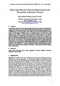
Sample UPnP sevice
As an example we consider a CD player. In the full model [13] this device has two different services, called ChangeDisc, and PlayCD, where Figure 1 illustrates only the first one. It allows a control point to add or remove discs from the CD player, to choose a disc to be placed on the tray, and to toggle (open/close) the door. The figure illustrates the relevant state information associated with the service.
DoorIsStuck CurrentSlot
DeviceSlots
10 9 8 7 6 5 4 3 2 1
. . . .
DoorIsOpen
S0
. .
Occupied Slots
.
Distributed real-time ASMs
This section briefly describes the model of distributed real-time ASMs and the related notions of concurrency and time. Aiming at an intuitive understanding, we treat here the underlying semantic concepts in a rather informal style.1 We start by explaining some basic concepts.
3.1
∆0
S1
∆1
S2
∆2
S3
Figure 2. Abstract State Machine run.
Figure 1. ChangeDisc service of a CD Player.
3
indicating that they have the same interpretation in all states of A. Non-static names are called dynamic. States of A are first-order structures with a fixed common base set. Different states may interpret dynamic names of V in different ways over the same base set. Unary relations defined on the base set have a special role; they can be interpreted as universes, or domains, classifying the objects under consideration. To represent additional computational resources, the base set contains a potentially infinite set, the reserve. Elements from the reserve serve to extend dynamic universes at run time. Given a vocabulary, A is defined by its program P and a set of distinguished initial states S0. The program P specifies possible state transitions of A in terms of finite sets of local function updates on a given global state. Such transitions are atomic actions. Starting from an initial state, executions of P produce finite or infinite runs as illustrated in Figure 2 (where the ∆ i refer to updates sets).
3.1.1 Program. A program P consists of transition rules. We define complex rules inductively as composition of basic update instructions using a few simple rule constructors. A basic update instruction operates on a given functions f and has the general form f(t1, t2,…, tn) := t0, where the ti ‘s (i = 0,…,n) are ground terms. The effect of this instruction is a local value assignment, where the value of f at the given location identified by t1, t2,…, tn is replaced by the value denoted by of t0. The canonical rule constructor is the block construct, also called “do in-parallel”, which allows for the synchronous parallel composition of rules. It has the general form illustrated below, where the “do in-parallel” part is optional (and usually is omitted). The update set computed by R over a given state is defined to be the union of the individual update sets as associated with R1 and R2 respectively. R ::= do in-parallel R1 R2
Abstract State Machines
An ASM A is defined over a fixed vocabulary V, some finite collection of function names and relation names. Technically speaking, relations are actually represented as Boolean valued functions; however, it is convenient to make this distinction. Names in V may be marked as static
1 For a rigorous mathematical definition of the theory of Abstract State Machines (formerly called evolving algebras), see the original literature [14, 15].
3.1.2 Examples. The following ASM program (written in AsmL) shows the part of the specification of the ChangeDisc service that is executed when invoked with the "AddDisc" action. The declarations of the function names are as follows, where all but SLOT and AllSlot are declared as dynamic. We will use the following style throughout this document to highlight AsmL code. universe SLOT DiscSlots as Set of SLOT var OccupiedSlots as Set of SLOT
0-7695-1435-9/02 $17.00 (c) 2002 IEEE
Proceedings of the 35th Annual Hawaii International Conference on System Sciences (HICSS-35’02) 0-7695-1435-9/02 $17.00 © 2002 IEEE
3
Proceedings of the 35th Hawaii International Conference on System Sciences - 2002
var DoorIsStuck var DoorIsOpen var CurrentSlot
as Boolean as Boolean as Integer
Upon invocation of the AddDisc action, the door of the CD player is opened (unless stuck) and one of its unoccupied slots (if any) is made current. The nondeterministic choose construct chooses some available slot. Notice that this is a specification of all the allowed behaviors. When this specification is executed, the choice is made randomly. However, any particular implementation conforming to this specification could use some deterministic algorithm for choosing an empty slot. AddDisc() = let emptySlots= DeviceSlots-OccupiedSlots if not(DoorIsStuck or emptySlots={}) then DoorIsOpen := true choose slot in emptySlots do CurrentSlot := slot else raise error condition
This is to illustrate the use of another key control construct of ASMs: do-for-all. We consider a specification of a hypothetical action that re-moves all currently occupied slots as a single transaction. RemoveDiscs() = forall s in OccupiedSlots do OccupiedSlots(s) := false
3.1.3 Abstract data structures. In order to simplify modeling and to stay close to the informal understanding, AsmL provides a rich background structure. In particular, we use dynamic sets and maps in our model. Both maps and sets may be viewed as aggregate entities and may be updated point-wise, for instance, as done for OccupiedSlots in the above example.
3.2
Real-time behavior
For dealing with real-time constraints, we employ a discrete notion of time abstractly representing time in a distributed system as global system time. Time values are represented as real numbers by the elements of a linearly ordered domain TIME. We can assume here that TIME is a subset of the real numbers and define the relation “≥” on time values through the corresponding relation on real numbers. Our notion of time is based on the view that we can only observe, but not control, how physical time evolves. Accordingly, we introduce a nullary function now taking values in TIME.
ASM runs. This way, we model timeout events through timer mechanisms that refer to the global system time. In a real-time context it is appropriate to assume that rules are fired instantaneously, i.e. as soon as a state is reached in which the rules are enabled. (Strictly speaking, one must assume here some non-zero delay to preserve the causal ordering of actions and events; though, this delay is immaterial from an application point of view.).
3.3
Distributed computation model
The distributed ASM model is a generalization of the basic model described in Section 3.1. A distributed ASM consists of a collection of autonomously operating agents interacting through globally shared states. Cooperatively these agents perform some distributed computation based on a concurrent execution model, where the computation steps of the individual agents are atomic actions.2 The underlying semantic model regulates interaction between agents so that potential conflicts are resolved according to the definition of partially ordered runs [14]. Agents are elements of a dynamic universe AGENT. Each agent has a program defining its behavior much like in the basic ASM model of Section 3.1. A distinguished nullary function me is used as a self reference for agents. When a new agent is introduced at run time, some program Program(me) from a statically defined set of programs is assigned to that agent. 3.3.1 The external world. Any interaction between the model and the external world, as observable at the respective interfaces, is reduced to interaction between two different categories of agents: (1) explicitly defined agents of the model, and (2) implicitly given agents of the environment. The non-deterministic nature of environment agents naturally reflects the system view of the external world. Thus the environment may also affect state transitions by altering dynamic functions. However, this does not mean that the environment behaves in a completely unpredictable way; rather one can formulate reasonable integrity constraints on external actions and events where appropriate. 3.3.2 Interleaving. In the current implementation of AsmL distributed agents are not fully supported in the language. In order to execute a distributed ASM written in AsmL, a top-level scheduling loop is needed to interleave the agents. Such a scheduler may be defined as follows. RunToplevel() = choose a in AGENT do Program(a)
var now as TIME
Intuitively, now represents the global system time as measured by some discrete clock. One can reasonably assume that the values of now change monotonically over
2 Note that we do not make any particular assumptions about the duration of atomic computation steps, although, they are basically considered as time-consuming actions.
0-7695-1435-9/02 $17.00 (c) 2002 IEEE
Proceedings of the 35th Annual Hawaii International Conference on System Sciences (HICSS-35’02) 0-7695-1435-9/02 $17.00 © 2002 IEEE
4
Proceedings of the 35th Hawaii International Conference on System Sciences - 2002
4
Abstract State Machine model of UPnP
A reasonable choice for the construction of an abstract UPnP protocol model is a distributed real-time ASM consisting of an arbitrary number of asynchronously communicating components. Intuitively, a component either represents a device, a control point or some fraction of the underlying communication network. With each component type we associate one or more interfaces such that any interaction between a component and any other component is strictly restricted to actions and events as observable at these interfaces. Additionally, actions and events in the external world, the environment into which the system under consideration is embedded, may affect the system behavior in various ways. For instance, the transport of messages over the communication network is subject to delays and sometimes messages may even get lost. Also, the system configuration itself may change as devices come and go. Such actions and events are basically unpredictable. We therefore introduce an additional GUI that allows for user-controlled interaction with the external world. The overall organization of the model is illustrated in Figure 3.
4.1
TCP/IP network and protocols
To model the network behavior, we define an abstraction of TCP/IP networks using standard network terminology [9]. Our network model is based on a distributed execution model faithfully reflecting the fact that a TCP/IP network usually consists of some (not further specified) collection of interconnected physical networks. However, we abstract here from topological details, e.g. how a global network is formed by interconnecting local networks by means of routers (or gateways); rather we describe the overall network behavior through a collection of concurrently operating communicators, each of which refers to some local network in conjunction with its adjacent routers. Conceptually, we separate the behavior of the network and its routers from the behavior of the hosts attached to this network as illustrated in Figure 4. Communicator 1
Router R2 Network 1
GUI External World (Visual Basic)
Controller Model synchronous
Communicator 2
R1
Network 2
Hosts R3
Interface
Device Model synchronous
Interface
Network Model Asynchronous Abstraction of TCP/IP networks
Figure 3. The distributed ASM model of UPnP.
At the component level, control points and devices are further decomposed, where each individual component splits into some collection of synchronously operating functional units. This decomposition is such that each of the resulting units participates in a different protocol step. Accordingly, we model control points and devices as parallel compositions of synchronously operating ASMs.
Figure 4. Communicators.
Based on the two standard transport level protocols, the User Datagram Protocol (UDP) and the Transmission Control Protocol (TCP), user level processes, or application programs, interact with each other by exchanging messages over the network. According to this view, there may be several application programs running on a single host. The address of an application program is given by the IP address of its host in conjunction with a unique protocol port number on this host. In our case, several control point programs may run on the same host. Devices, however, are considered as individual hardware units; therefore they are identified with the hosts on which they run.
4.2
Basic agent types
This section introduces various universes identifying the basic types of agents and gives an overview on how they are related with each other. The main types of agents are the following. universe AGENT universe COMMUNICATOR
0-7695-1435-9/02 $17.00 (c) 2002 IEEE
Proceedings of the 35th Annual Hawaii International Conference on System Sciences (HICSS-35’02) 0-7695-1435-9/02 $17.00 © 2002 IEEE
5
Proceedings of the 35th Hawaii International Conference on System Sciences - 2002
universe CONTROLPOINT universe DEVICE
AGENT
The Dynamic Host Configuration Protocol (DHCP) enables automatic configuration of IP addresses when adding a new host to a network. We model interaction between a DHCP server and the DHCP client of a device explicitly only as far as the device side is concerned. The server side is abstractly represented through one or more external DHCP server agents whose behavior is left implicit. In our model, the DHCP server represents another type of application program.
mailbox: Set of MESSAGE
COMMUNICATOR routingTable: ADDRESS → Set of COMMUNICATOR adressTable: ADDRESS → Set of ADDRESS
universe DHCPSERVER
APPLICATION
Control points, devices and DHCP servers are collectively called applications. The applications and the communicators are modeled as autonomous agents. APPLICATION = CONTROLPOINT ∪ DEVICE ∪ DHCPSERVER AGENT = APPLICATION ∪ COMMUNICATOR
An overview of the various agent types and the relations between them is presented in the form of a UML class diagram in Figure 5.
4.3
address: ADDRESS network: COMMUNICATOR
DEVICE status: DEVICESTATUS services: Set of SERVICE type: String uid: String
CONTROLPOINT search: DATA action: DATA
DHCPSERVER
Timeout events
A universe DURATION represents finite time intervals as differences between time values. universe DURATION
Every agent a may employ several distinct timers for different purposes. Each individual timer t has its own predefined duration effectively determining the expiration time when setting t. In a given state, a timer t is active if and only if its expiration time time(a,t) is greater than the value of now. Otherwise, t is said to be expired. universe TIMER = {discovery, …} duration(me as AGENT, t as TIMER) as DURATION var time(me as AGENT, t as TIMER) as TIME
For a given timer t of an agent, the operation of setting t can be defined as follows. SetTimer(me as AGENT, t as TIMER) = time(me, t):= now + duration(me, t)
In a given state, a predicate Timeout indicates for a given timer t and agent me whether or not t has expired. Timeout(me as AGENT, t as TIMER) as Boolean = now ≥ time(me, t)
Figure 5. UML class diagram of the agents.
4.4
Addressing and messaging
This section defines the representation of addresses and messages together with the mechanisms for sending and receiving messages. Our model abstractly reflects the view of the transports TCP and UDP. At the given level of abstraction, the actual difference between TCP and UDP is that the former is reliable whereas the latter provides a best-effort, connectionless packet delivery service, i.e. message may get lost, duplicated or received out of order. 4.4.1 Addresses. We introduce a static universe ADDRESS of IP addresses extended by protocol port numbers to refer to the global TCP/UDP address space. Each application under consideration has a dynamic function address identifying an element from ADDRESS. universe ADDRESS var address(me as APPLICATION) as ADDRESS
When a new device is added to the network, it does not yet have an IP address, but uses its hardware address for communication with a DHCP server. We abstractly model hardware addresses as elements of some static universe HWADDRESS. universe HWADDRESS hwAddress(me as DEVICE) as HWADDRESS
0-7695-1435-9/02 $17.00 (c) 2002 IEEE
Proceedings of the 35th Annual Hawaii International Conference on System Sciences (HICSS-35’02) 0-7695-1435-9/02 $17.00 © 2002 IEEE
6
Proceedings of the 35th Hawaii International Conference on System Sciences - 2002
4.4.2 Messages. Messages are uniformly represented as elements of a dynamic universe MESSAGE. Each message is of a certain type from the static universe MSGTYPE. The message type in fact determines whether a message is to be transmitted using UDP or TCP, though we do not make this distinction explicit here. universe MESSAGE initially {} universe MSGTYPE = {advertisement, revocation, ...}
A message uniquely identifies a sender, a receiver, a message type, and the actual message data, or payload. The payload can be any finite representation of data to be transferred from a sender to a receiver. To limit the maximum number of routers that a message can pass on its way from the sender host to a destination host, a timeto-live or TTL, is assigned when the message is created. (UPnP defines the initial TTL to be 4). universe DATA var sndr(me as var rcvr(me as var type(me as var data(me as var ttl (me as
MESSAGE) MESSAGE) MESSAGE) MESSAGE) MESSAGE)
as as as as as
ADDRESS ADDRESS MSGTYPE DATA {0,1,2,3,4}
4.4.3 Messaging. An application is running on some host connected to one or more local networks. The operation of sending a message as well as the delivery of a message both require some form of direct interaction between this host and one of its local networks. We can assume that the network is uniquely determined by the application. network(me as APPLICATION) as COMMUNICATOR
Local Mailboxes. Every agent has a local mailbox for storing messages until these messages will be processed. According to this view, the mailbox of a network agent represents the set of messages that are currently in transit on the related network and its routers. The mailbox of an application represents its local input port as identified by the respective port number for this application. var mailbox(me as AGENT) as Set of MESSAGE initially {}
4.5
High-level protocol model
In this section we define a high-level ASM model of the UPnP protocol. In [13], this model is further refined into an executable model by adding more details. 4.5.1 Initial states. An initial state reflects the particular system configuration under consideration. As such it identifies some finite collection of a priori given agents, one for each control point, each device and each communicator.
4.5.2 Network model. Assume that both TCP and UDP are used as protocols for the transfer of messages between applications running on different machines. Since UDP is based on the same unreliable datagram delivery semantics as IP [9], it is in the responsibility of an application to tolerate this behavior. Delivery and Routing. Collectively, the communicators solve the task of globally transferring messages between applications running on hosts connected to the network. Communicators thus imitate the behavior of IP routers, where we encode the topological information in two separate tables, an address table and a routing table. An addressTable is a mapping from addresses of multicast groups to addresses of related group members. Some of the resulting addresses may be local, some not. addressTable(me as COMMUNICATOR, a as ADDRESS) as Set of ADDRESS
A routingTable maps non-local addresses to the correct neighboring communicators. routingTable(me as COMMUNICATOR, a as ADDRESS) as COMMUNICATOR
Message Transfer. The transfer of messages may be delayed in an unpredictable manner depending on resource limitations of the underlying physical network. Since we abstract here from lower level network layers, the decision whether a messages is ready to be delivered in a given state of the network is expressed through an externally controlled unary predicate ReadyToDeliver defined on messages. (Notice that for some UDP message m the condition ReadyToDeliver(m) may never hold, implying that the message effectively gets lost.) var ReadyToDeliver(me as MESSAGE) as Boolean
Program. The program of a communicator performs three different steps: 1) limited broadcasting within the local network; 2) delivery of multicast messages on a local network; 3) routing of messages through a global network. To identify local networks, a unique network identifier, called netid, is associated with each communicator. The network identifier can be derived from an IP address by inspecting the network mask that is part of the address. universe NETID netid(me as COMMUNICATOR) as NETID netid(a as ADDRESS) as NETID
A communicator is responsible for delivering messages that are ready to be delivered, in which case the message is removed from the mailbox. In the AsmL rules below, we use global rule macros to support modular descriptions and stepwise refinements. Formally, such macros are syntactic abbreviations that often are parameterized. That is, each occurrence of a macro within a rule is to be replaced by the related macro
0-7695-1435-9/02 $17.00 (c) 2002 IEEE
Proceedings of the 35th Annual Hawaii International Conference on System Sciences (HICSS-35’02) 0-7695-1435-9/02 $17.00 © 2002 IEEE
7
Proceedings of the 35th Hawaii International Conference on System Sciences - 2002
definition, effectively replacing formal parameters with actual ones. Program(me as COMMUNICATOR)= choose msg in me.mailbox where ReadyToDeliver(msg) do me.mailbox(msg) := false Deliver(me, msg)
Delivery can either mean limited broadcasting, or the destination address is resolved, using the address table, to a set of outbound addresses. Each of those addresses is either local or non-local. Deliver(me as COMMUNICATOR, msg as MSSAGE)= if m.rcvr = broadcast then Broadcast(me, msg) else forall adr in addressTable(me, msg.rcvr) do if netid(adr) = me.netid then DeliverLocally(me, msg, adr) else Route(me, msg, adr)
Limited broadcasting implies delivery to all local applications. Broadcast(me as COMMUNICATOR,m as MESSAGE)= forall app in APPLICATION where app.network = me do DeliverMessage(m, app.address, app)
Local delivery of a message is accomplished by finding out the local destination and delivering the message to it. DeliverLocally(me as COMMUNICATOR, msg as MESSAGE, adr as ADDRESS)= choose app in APPLICATION where app.address = a do DeliverMessage(msg, adr, app)
A message is routed to a neighboring communicator only if its TTL is greater than 0. Route(me as COMMUNICATOR, msg as MESSAGE, adr as ADDRESS) = if ttl(m) > 0 then let c = routingTable(me, adr) if c ≠ undef then DeliverMessage(msg,adr,c)
The operation of delivering a message to the mailbox of a given agent is defined below. Applications and communicators are treated uniformly. They are both agents that have a mailbox and the operation performed on this mailbox (i.e., inserting a copy of some message) does not depend on the particular type of agent. DeliverMessage(msg as MESSAGE, adr as ADDRESS, agt as AGENT) = let m = new MESSAGE m.sndr := msg.sndr m.rcvr := adr m.data := msg.data
m.type := msg.type m.ttl := msg.ttl - 1 agt.mailbox:= agt.mailbox ∪ {msg}
Overall Network Behavior. The above program describes one atomic step of a communicator. In a particular network model there may be one or more concurrently operating communicators. Note that only adjacent communicators may interact with each other by inserting messages into each others mailboxes. Adjacency here is defined by the routing tables. 4.5.3 Device model. This model abstractly describes the UPnP protocol core. The status of a device may be one of the following three modes, where byebye means that the device is about to become inactive. universe DEVICESTATUS = {inactive, alive, byebye} var status (me as DEVICE) as DEVICESTATUS
The device program handles all the protocol phases (all of which may overlap with each other). Program(me as DEVICE) = if me.status ≠ inactive then RunAddressing(me) RunDiscovery(me) RunDescription(me) RunControl(me) RunEventing(me) RunPresentation(me)
Every device is connected to a set of services through abstract service interfaces. universe SERVICE srvcs(me as DEVICE) as Set of SERVICE
We just show one of the protocol phases here (see the technical report for details). The control part executes only if the device has an address. It then handles some request that has a matching service by calling the corresponding service and deletes that request. RunControl(me as DEVICE) = if me.adr ≠ undef then choose msg in me.mailbox, s in me.srvcs where IsServiceRequest(msg,s) do CallService(msg,s) me.mailbox(msg) := false
5
Related work
General introductions to domain-specific languages are given in [10, 19]. The annotated bibliography [10] categorizes the domains of various domain-specific languages into five different groups. The group on software engineering is further subdivided into several subgroups including one for software architectures. The main focus of a software architecture description language (ADL) is to provide features for modeling a
0-7695-1435-9/02 $17.00 (c) 2002 IEEE
Proceedings of the 35th Annual Hawaii International Conference on System Sciences (HICSS-35’02) 0-7695-1435-9/02 $17.00 © 2002 IEEE
8
Proceedings of the 35th Hawaii International Conference on System Sciences - 2002
system's conceptual architecture, rather than its actual implementation. Recent surveys of ADLs are given in [8, 23]. This is a quote from [23] regarding the prevailing argument for using ADLs: They are necessary to bridge the gap between informal, "boxes and lines" diagrams and programming languages which are deemed too low-level for application design activities.
We have not been able to find a definite agreement in the literature on the precise definition of which languages classify as ADLs. Below we argue why AsmL may be considered as an ADL in terms of the general definition and classification frame-work of ADLs proposed in [23]. An ADL must provide means for explicit specification of the building blocks of an architectural description. The building blocks are 1) components, 2) connectors, and 3) configurations. Components in AsmL are ASMs together with a collection of interfaces defining the interaction points with the environment. The interfaces may be declared as native COM [7] interfaces, automation interfaces or abstract model interfaces, depending on their usage. For example, in the UPnP model, device models are components that interact with the communicator through abstract model interfaces and with the GUI trough automation interfaces. Connectors are special components for modeling the interaction of other components. Their behavior is clearly separated from the core behavior of the model. For example, in the UPnP model the communicators are the connectors; indeed they do not reflect any UPnP specific behavior. Configurations describe the architectural structure of the system, i.e. the topology of the components. In AsmL, configurations are normally described explicitly in the state. For example, the address table and the routing table in the UPnP protocol constitute the configurations. However, AsmL does not have an explicit configuration sublanguage, which, according to [23], may be seen as a counterargument for AsmL being classified as an ADL. The main strength of AsmL is the unified semantic model based on ASMs [14]. This is in contrast to many existing ADLs, which lack formal semantics completely, or use different formal semantics for components vs. connectors [23]. A rigorous semantics is often a prerequisite for many tool generators [20]. AsmL specifications can be used for automatic test case generation [17], conformance checking [3, 4], and to provide behavioral interfaces for components [2]. Methodological guidelines and epistemological reasons how and why the ASM paradigm offers a mathematically well founded approach to high-level systems design and analysis of complex system behavior, also in relation to other formal methods, are discussed in [5].
6
Conclusions
In this paper we showed how to construct a high-level Abstract State Machine (ASM) model for the Universal Plug and Play Architecture based on the ASM paradigm and AsmL, the Abstract state machine Language, developed at Microsoft Research. In general, the proposed modeling approach requires three equally important steps: 1) construction of the high-level model, 2) its refinement to a lower level model that can be simulated, and 3) construction of a GUI for control and animation of simulation runs. In this paper we focused on some parts of 1). For a comprehensive description of the full model including the GUI, sample control points and services, we refer to our technical report [13]. Conceptually, we concentrated here on interoperability aspects rather than on details of individual components. Components operate concurrently and interact with each other by exchanging messages over the communication network. They use actuators and sensors to interact with the external world, the environment into which the entire system is embedded. The ASM paradigm allows us to combine synchronous with asynchronous execution models in one uniform model of computation. That is, the component models themselves are parallel compositions of synchronously operating ASMs, whereas the system as a whole is formed by a composition of asynchronously operating components, called agents.
7
Acknowledgements
We thank Jeffrey Schlimmer from the UPnP group at Microsoft for several inspiring discussions and helpful background information about the development and standardization of UPnP. We thank Colin Campbell at Modeled Computation LLC for his valuable criticism and his active support on modeling individual UPnP devices. We also thank the anonymous referees for many useful comments that greatly helped to improve the final paper and for pointing out relevant literature in the area of domain-specific languages.
8
References
1.
Abstract State Machines, website: www.eecs.umich.edu/ gasm/.
2.
M. Barnett and W. Schulte. The ABCs of Specication: AsmL, Behavior, and Components, Informatica. To appear in 2002.
3.
M. Barnett, C. Campbell, W. Schulte, and M. Veanes. Specification, simulation and testing of COM components using Abstract State Machines. In Formal Methods and Tools for Computer Science, Eurocast 2001,
0-7695-1435-9/02 $17.00 (c) 2002 IEEE
Proceedings of the 35th Annual Hawaii International Conference on System Sciences (HICSS-35’02) 0-7695-1435-9/02 $17.00 © 2002 IEEE
9
Proceedings of the 35th Hawaii International Conference on System Sciences - 2002
pp. 266-270. IUCTC Universidad de Las Palmas de Gran Canaria, February 2001. 4.
5.
M. Barnett, L. Nachmanson, and W. Schulte. Conformance checking of components against their nondeterministic specifications. Technical Report MSR-TR2001-56, Microsoft Research, June 2001. E. Börger, High Level System Design and Analysis using Abstract State Machines. In D. Hutter, W. Stephan, P. Traverso, M. Ullman, eds., Current Trends in Applied Formal Methods (FM-Trends 98). Springer LNCS 1641, pp. 1-43, 1999.
15.
Y. Gurevich. Sequential Abstract State Machines Capture Sequential Algorithms", ACM Transactions on Computational Logic, vol. 1, no. 1, July 2000, 77-111.
16.
Y. Gurevich. The ASM Paradigm, in Proc. ASM'2001, 2001.
17.
W. Grieskamp, Y. Gurevich, W. Schulte and M. Veanes. Testing with Abstract State Machines. In Proc. ASM'2001.
18.
Y. Gurevich, W. Schulte and M. Veanes, Toward Industrial Strength Abstract State Machines, in Proc. ASM'2001, 2001.
19.
J. Heering. Application software, domain-specific languages, and language design assistants, in: Proceedings SSGRR 2000 International Conference on Advances in Infrastructure for Electronic Business, Science, and Education on the Internet, May 2000.
6.
E. Börger, U. Glässer and W. Müller. Formal Definition of an Abstract VHDL'93 Simulator by EA-Machines. In C. Delgado Kloos and Peter T. Breuer, editors, Formal Semantics for VHDL, Kluwer Academic Publishers, 1995, 107-139.
7.
D. Box, Essential COM, Addison-Wesley, Reading, MA, 1998.
20.
8.
P. Clements, A Survey of Architecture Description Languages Eighth Intl. Workshop in Software Specification and Design, Paderborn, Germany, March 1996.
J. Heering and P. Klint, Semantics of programming languages: A tool-oriented approach, ACM SIGPLAN Notices, 35(3):39-48, March 2000.
21.
ITU-T Recommendation Z.100: Languages for Telecommunications Applications - Specification and Description Language (SDL), Annex F: SDL Formal Semantics Definition, International Telecommunication Union, Geneva, 2000.
9.
D. E. Comer. Internetworking with TCP/IP, Principles, Protocols, and Architectures. Prentice Hall, 2000.
10.
A. van Deursen, P. Klint, and J. Visser. Domain-Specific Languages: An Annotated Bibliography. ACM SIGPLAN Notices, 35(6):97-105, June 2000.
22.
Microsoft Research, Foundations of Engineering, Redmond, USA, research.microsoft.com/foundations.
11.
R. Eschbach, U. Glässer, R. Gotzhein and A. Prinz. On the formal semantics of SDL-2000: a compilation approach based on an Abstract SDL Machine. In Abstract State Machines - Theory and Applications. Y. Gurevich, P.W. Kutter, M. Odersky and L. Thiele (Eds.), Lecture Notes in Computer Science, Vol. 1912, Springer, 2000.
23.
N. Medvidovic and R.N. Taylor, A Classification and Comparison Framework for Software Architecture Description Languages, IEEE Transactions on Software Engineering, 26(1):70-93, January 2000.
24.
R. Stärk, J. Schmid and E. Börger. Java and the Java Virtual Machine: Definition, Verification, Validation. Springer, 2001.
25.
Universal Plug and Play Forum. Official web site of the UPnP Forum. URL: www.upnp.org.
26.
UPnP Device Architecture V1.0. Microsoft Universal Plug and Play Summit, Seattle 2000, Microsoft Corporation, Jan. 2000.
12.
R. Eschbach , U. Glässer, R. Gotzhein, M. von Löwis and A. Prinz. SDL Formal Semantics: Compiling and Running SDL Specifications as ASM Models. Submitted for publication in E. Börger and U. Glässer (editors), Proc. ASM’2001.
13.
U. Glässer, Y.Gurevich and M. Veanes, Universal Plug and Play Machine Models, Microsoft Research, Technical Report MSR-TR-2001-59, June 15, 2001.
14.
Y. Gurevich. Evolving Algebras 1993: Lipari Guide, Specification and Validation Methods, ed. E. Börger, Oxford University Press, 1995, 9-36.
0-7695-1435-9/02 $17.00 (c) 2002 IEEE
Proceedings of the 35th Annual Hawaii International Conference on System Sciences (HICSS-35’02) 0-7695-1435-9/02 $17.00 © 2002 IEEE
Software website:
10