High-Throughput Pairwise Point Interactions in Anton, a Specialized Machine for Molecular Dynamics Simulation Richard H. Larson, John K. Salmon, Ron O. Dror, Martin M. Deneroff, Cliff Young, J.P. Grossman, Yibing Shan, John L. Klepeis, and David E. Shaw* D. E. Shaw Research, 39th Floor, Tower 45, 120 West 45th Street, New York, NY 10036 {larsonr,salmonj,dror,deneroff,youngc,grossmaj,shan,klepeisj,shaw}@deshaw.com* Abstract
1. Introduction Anton, a massively parallel special-purpose machine scheduled for completion in 2008 [23], is designed to execute millisecond-scale molecular dynamics (MD) simulations, approximately three orders of magnitude beyond the duration of the longest current MD simulations [8, 20]. Simulations of this scale could allow scientists and drug developers to visualize for the first time critically important biochemical phenomena that cannot currently be observed in laboratory experiments, including the “folding” of proteins into their native three-dimensional structures, the structural changes that underlie protein function, and the interactions between two proteins or between a protein and a candidate drug molecule [6, 12, 13, 19]. The initial version of Anton will comprise 512 identical processing nodes, each containing a specialized MD computation engine implemented as a single ASIC in 90 nm technology, connected to form a threedimensional torus [23]. This paper describes the highthroughput interaction subsystem (HTIS) of the Anton ASIC, which handles the most arithmetically intensive portions of an MD computation. The HTIS accelerates the pairwise interaction computations that dominate an MD simulation by over two orders of magnitude relative to state-of-the-art general-purpose microprocessors. The Amdahl’s law bottlenecks exposed by this acceleration are addressed by the flexible subsystem, described in a companion paper [14].
Anton is a massively parallel special-purpose supercomputer designed to accelerate molecular dynamics (MD) simulations by several orders of magnitude, making possible for the first time the atomic-level simulation of many biologically important phenomena that take place over microsecond to millisecond time scales. The majority of the computation required for MD simulations involves the calculation of pairwise interactions between particles and/or gridpoints separated by no more than some specified cutoff radius. In Anton, such range-limited interactions are handled by a high-throughput interaction subsystem (HTIS). The HTIS on each of Anton’s 512 ASICs includes 32 computational pipelines running at 800 MHz, each producing a result on every cycle that would require approximately 50 arithmetic operations to compute on a general-purpose processor. In order to feed these pipelines and collect their results at a speed sufficient to take advantage of this computational power, Anton uses two novel techniques to limit inter- and intra-chip communication. The first is a recently developed parallelization algorithm for the range-limited N-body problem that offers major advantages in both asymptotic and absolute terms by comparison with traditional methods. The second is an architectural feature that processes pairs of points chosen from two point sets in time proportional to the product of the sizes of those sets, but with input and output volume proportional only to their sum. Together, these features allow Anton to perform pairwise interactions with very high throughput and unusually low latency, enabling MD simulations on time scales inaccessible to other general- and special-purpose parallel systems.*
*
1.1 MD Workloads and the HTIS A typical system representing a protein surrounded by water might contain 25,000 atoms, each represented by one particle. Simulating this system for one millisecond requires the computation of a total of roughly 1019 interactions between pairs of nearby particles. In order for a 512-node machine to perform
Correspondence to
[email protected]. David E. Shaw is also with the Center for Computational Biology and Bioinformatics, Columbia University, New York, NY 10032.
978-1-4244-2070-4/08/$25.00 ©2008 IEEE
331
ture that supports direct product selection reduction operations (DPSRs), which take two sets of points and perform computation proportional to the product of the set sizes but only require input and output volume proportional to the sum of the sizes. The HTIS also provides specialized support for the NT method, a parallelization scheme which significantly reduces interASIC communicaton requirements relative to traditional parallelization methods [22].
1.2 The Structure of an MD Simulation An MD computation simulates the motion of a collection of atoms (the chemical system) over a period of time according to the laws of classical physics. The chemical system occupies a small parallelepiped (the global cell), typically tens of angstroms on a side, filled with tens or hundreds of thousands of atoms. For brevity, we describe only those details of MD calculations required to explain the operation of the HTIS. Numerous more complete surveys of MD methodology are available [1, 13]. For expository simplicity, we assume that each atom is represented by a single particle. An MD computation breaks time into a series of discrete time steps, each representing a few femtoseconds of simulated time. Figure 1 shows a breakdown of the major computational tasks involved in an MD time step. The shaded leaves represent the computations performed by the HTIS. The remaining leaves correspond to tasks that lend themselves better to a fully programmable engine, both because they may vary substantially from one simulation to another and because they constitute a minority of the computational load. On Anton, they are performed by the flexible subsystem. The majority of the computation in an MD simulation involves range-limited pairwise particle interactions, interactions between pairs of points (particles or gridpoints) separated by less than some cutoff radius. In principle, both van der Waals and electrostatic forces act between all pairs of particles in the simulated system. Van der Waals forces fall off sufficiently quickly with distance that they are generally neglected for pairs of particles separated by more than some cutoff radius, usually chosen between 5 and 15 Å. Anton uses a method for fast electrostatics calculation called k-space Gaussian split Ewald, or k-GSE [21], which avoids explicit computation of interactions between distant pairs of atoms and which maps to our specialized hardware more effectively than previously described fast electrostatics methods. In k-GSE, electrostatic interactions are divided into two contributions. The first decays rapidly with particle separa-
Figure 1. Major computational tasks in an MD simulation on Anton. Each MD time step consists of force calculation followed by integration. The forces in MD consist of bonded and nonbonded terms. The nonbonded terms include van der Waals and electrostatic interactions. The electrostatic interactions are split into a pairwise electrostatic force component and a grid-based electrostatic force component. The latter is computed by spreading charge to a grid, performing computation in Fourier space (including forward and inverse Fourier transforms), and calculating force on particles by interpolating grid potentials. The HTIS is responsible for the shaded tasks. this simulation in a month, each node must compute over 7,000 interactions per microsecond, in addition to the overhead associated with other required communication and computation. Evaluating the functions associated with each of these interactions requires roughly 50 arithmetic operations on a typical programmable processor. Anton’s HTIS delivers the tremendous arithmetic throughput required to reach millisecond-scale simulations using an array of 32 pairwise point interaction pipelines (PPIPs), each of which runs at 800 MHz and is capable of computing one interaction per clock cycle, for a theoretical peak rate of 25,600 interactions per microsecond per ASIC. In order to keep the pipelines busy with useful computation, the remainder of the HTIS must determine pairs of points that need to interact, feed them to the pipelines, and aggregate the pipelines’ outputs. This proves a formidable challenge given communication bandwidth limitations between ASICs, between the HTIS and other subsystems on the same ASIC, and between pipelines within the HTIS. We address this problem using an architec-
332
Table 1. Representative functional forms of range-limited pairwise interactions required for MD simulations. These are shown to illustrate the complexity of the computation performed by the HTIS, but the details are beyond the scope of this paper. The distance between the interacting points is r, and the vector from one point to the other is r. Van der Waals and electrostatic parameters associated with individual points have subscripts 1 or 2. The remaining parameters, σs, σ and c, are associated with the kGSE method [21] and are constant across interactions.
Electrostatic and van der Waals particle-particle force
⎛ q q ⎪⎧ ⎛ − r 2 ⎞ ⎪⎫ 2r ⎛ r ⎞ + F = r ⎜ 1 3 2 ⎨erfc ⎜ exp ⎜ 2 ⎟ ⎬ ⎟ ⎜ r ⎪ ⎝ 2σ ⎠ 2πσ 2 ⎝ 2σ ⎠ ⎭⎪ ⎩ ⎝ +
24 ε1ε 2
( (σ
1
+σ2)
−7 −4 ⎧ ⎛ 2 ⎞ ⎛ ⎞ ⎫⎪⎟⎞ r2 r ⎪ ⎜ ⎟ −⎜ ⎟ ⎬ 2 2 ⎨ 2 ⎜ ( (σ 1 + σ 2 ) 2 )2 ⎟ ⎪⎟⎟ 2 ) ⎪ ⎜⎝ ( (σ 1 + σ 2 ) 2 ) ⎟⎠ ⎝ ⎠ ⎭⎠ ⎩
Electrostatic and van der Waals particle-particle energy
⎛ r ⎞ −6 −3 q1q2 erfc ⎜ ⎧⎛ ⎟ ⎞ ⎛ ⎞ ⎫⎪ r2 r2 ⎪⎜ 2σ ⎠ ⎝ ⎟ ⎜ ⎟ + 4 ε1ε 2 ⎨ − E= ⎬ 2 ⎜ ( (σ 1 + σ 2 ) 2 ) 2 ⎟ ⎪ r ⎪⎜⎝ ( (σ 1 + σ 2 ) 2 ) ⎟⎠ ⎝ ⎠ ⎩ ⎭
Charge spreading (gridpoint-particle)
ρ1 =
Force interpolation (gridpoint-particle)
F2 =
( (
q2 2πσ s2 rφ1q2c 2πσ s2
)
3
)
3
⎛ −r 2 ⎞ exp ⎜ 2 ⎟ ⎝ 2σ s ⎠ ⎛ −r 2 ⎞ exp ⎜ 2 ⎟ ⎝ 2σ s ⎠
tion, and is thus computed directly for all particle pairs separated by less than the cutoff radius. This pairwise electrostatic contribution, together with the van der Waals interactions, make up the particle-particle interactions. The second contribution (grid-based electrostatic forces) decays more slowly but can be computed efficiently in Fourier space. Charge must be mapped from particles to nearby gridpoints (charge spreading) before transforming to Fourier space, and forces on particles must be calculated from results at nearby gridpoints (force interpolation) after transforming back from Fourier space. Charge spreading and force interpolation constitute the gridpointparticle interactions. The HTIS performs range-limited pairwise particle interactions, including both particle-particle and gridpoint-particle interactions. In both cases, pairs of points are interacted if they are within a specified cutoff radius, and the magnitude of the interaction is a function of the distance between the two points. Table 1 shows examples of the terms evaluated for the various interactions. Other forms are also widely used, requiring the HTIS to provide considerable flexibility in the functional forms it supports. For expository simplicity, this paper describes HTIS operation in terms of particle-particle interactions for force computation, but its actual operation is more general.
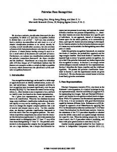
2. Direct Product Selection Reduction Operations The 32 PPIPs on an Anton ASIC can sustain an aggregate input plus output data rate in excess of 10 Tbit/s. A naïve implementation that transferred the inputs and outputs of each pipeline between the HTIS and other subsystems would require communication bandwidth beyond the limits of current technology. Thus, the architectural challenge of the HTIS is to organize both the hardware and calculation so that high pipeline utilization can be sustained with achievable communication bandwidth. Our solution is to formulate the range-limited pairwise interactions of MD in terms of direct product selection reduction operations (DPSRs), illustrated in Figure 2. Abstractly, a DPSR takes two input sets P and T with cardinality |P| and |T|, respectively. First, the DPSR forms the direct product of P and T, i.e., the complete set of ordered pairs consisting of one item from P and another from T. A selection criterion filters the pairs in the product set and an interaction is computed on each pair that passes. The results of the interactions are then reduced (summed), producing one output per input, for a total of |P|+|T| outputs in all. The output associated with each input is the sum
333
forces on its own particles by importing all particles within the cutoff distance of its home box, then computing interactions both between pairs of particles within the local home box and between local and imported particles. Newton’s third law guarantees that a pair of particles exert equal and opposite forces on one another. In order to avoid performing the same force computation on two different nodes, each node can instead import particles only from the smaller “halfshell” region illustrated in Figure 3(a), and then export resulting forces on the imported particles to that region when computation is complete. A number of recently introduced methods for parallelizing range-limited pairwise interactions require significantly less communication bandwidth than traditional parallelization methods [4, 5, 22, 24]. In these neutral territory methods, some of which have been used effectively on clusters of general-purpose processors [3], the interaction between two particles is sometimes computed by a node on which neither particle resides [5]. Anton uses one such method, the NT method, in which each node computes interactions between particles in a tower region and particles in a plate region (Figure 3(b)). Both of these regions contain the home box. The NT method considers interactions between each particle in the tower and each particle in the plate, but computes only those that satisfy certain selection rules. One of these rules requires that the distance between the particles be less than the cutoff, while the others ensure that each interaction is computed only once. A DPSR implements precisely the calculations required by the NT method1. The input sets T and P correspond to the tower and plate. Selection is performed using the NT method’s selection rules. The reduction is the summation of vector forces, giving a resultant force on each atom in the plate and each atom in the tower. For example, a cubical system of 25,000 atoms running on a 512-node configuration of Anton would have cubical home boxes roughly 8 Å on a side containing about 50 atoms each. Using a cutoff radius of 13 Å, each node would have about 220 atoms in its tower (T) and 430 atoms in its plate (P). The product set consists of about 100,000 pairs, of which about 23,000 satisfy the selection rules. Thus, each node must import and export about 550 particles (the tower and plate particles not in the home box), consider selection rules for about 100,000 pairs, and evaluate about 23,000 interactions. These numbers
Step 1. Direct product generation and selection input P
Step 2. Function evaluation and reduction
sum down columns
output P
Figure 2. Direct product selection reduction operation (DPSR). In step 1, a selection criterion is applied to all pairs consisting of an element of set P and an element of set T. Pairs that satisfy the selection criterion are circled. In step 2, a function is applied and the results are summed down the columns and across the rows, producing |P|+|T| distinct outputs. over all interactions involving that input. In a DPSR, the input and output data volume is proportional to |P|+|T|, while the amount of computation is proportional to |P||T|. For all but the smallest values of |P| and |T|, |P||T| is much larger than |P|+|T|, providing the leverage needed to match I/O bandwidth to computational throughput. Anton uses a novel parallelization method for range-limited pairwise interactions, the NT method, which can be formulated as a set of DPSRs. In Anton, as in most parallel MD codes, the global cell is divided into a regular grid of smaller parallelepipeds, which will be referred to here as boxes. Each node updates the positions and velocities of particles in one box, referred to as the home box of that node and of those particles. In traditional spatial decomposition methods for parallelizing range-limited pairwise interactions [18], the node that computes the interaction between two particles is always a node on which one or both particles resides. For example, each node might compute
1 The calculations required by traditional spatial decomposition methods can also be expressed as DPSRs and executed on Anton, but they will typically deliver lower performance than the NT method.
334
Figure 3. Import regions associated with several parallelization methods for range-limited pairwise interactions. (a) In a traditional spatial decomposition method, each node imports particles in the half-shell region so that they can interact with particles in the home box. (b) In the NT method, each node computes interactions between particles in a tower region and particles in a plate region. Both of these regions include the home box, but particles in the remainder of each region must be imported. (c) In a variant of the NT method used for gridpoint-particle interactions, the plate region is larger. Both the tower and the plate include the home box, which is hidden in this illustration. are purely illustrative; Anton can scale up to much larger chemical systems. Anton also uses a variant of the NT method to parallelize charge spreading and force interpolation. In this case, gridpoints in the tower are interacted with particles in the plate, or vice versa. Newton’s third law does not reduce the computation required for gridpoint-particle interactions because the calculations are unidirectional (from particle to gridpoint in charge spreading, and from gridpoint to particle in force interpolation). As a result, the plate import region must be enlarged as shown in Figure 3(c), and the only selection rule is the one requiring that the distance between the points be less than the cutoff. The idea of matching bandwidth to computation by appropriately blocking an algorithm so that input and output scale more slowly than computation is not new. It is the basic idea behind the highly successful BLAS3 matrix-matrix routines for linear algebra [7].
to each of the PPIMs through the particle distribution network. The selection criterion is applied in parallel by 8 match units per PPIM (256 in all), identifying all pairs that meet the selection criterion in two cycles. Interactions between selected pairs are computed by one PPIP per PPIM (32 in all), each 28 stages deep and running at 800 MHz. The PPIPs give Anton its computational power, providing each HTIS with hundreds of times the throughput of a modern highperformance general-purpose processor (see Section 4). Two separate reductions are applied to the outputs of the PPIP; forces on points in T are summed in the tower force arrays (one per PPIM, 32 in total), while those on particles in P are summed on the systolic force reduction network. Other hardware components in the HTIS support import and export of data through the ASIC’s communication subsystem and buffering of data in particle memory. The overall operation of the HTIS is under the control of the interaction control block (ICB), a programmable general-purpose processor with HTISspecific instructions. The entire HTIS requires about one third of Anton’s 17-mm-by-17-mm die.
3. Architecture The HTIS, illustrated in Figure 4, is a hardware implementation of an MD-specific DPSR. Up to 16 points from one set, T, are first distributed to the tower particle array in each of 32 pairwise point interaction modules (PPIMs), for a total of up to 512 tower particles. Then points from a second set, P, are streamed
335
Figure 4. High-throughput interaction subsystem and detail of a single pairwise point interaction module (PPIM). Arrows indicate the direction of data flow in the particle distribution and force reduction networks. Each chain of 8 PPIMs in these networks is folded in the floor plan so that the inputs and outputs can be routed to a central core.
3.1 Particle Memory and Interaction Control Block
3.2 PPIM Array and Particle Distribution Network
Communication on Anton is one-sided. That is, the sender explicitly specifies a destination address and expects no confirmation of receipt. From the perspective of the receiver, data arrives asynchronously. Particle memory decouples the operation of the HTIS from the rest of the chip by providing a destination to which other subsystems can send data to be processed by the HTIS. Particle memory is an interleaved multiported RAM structure that can be simultaneously written with data arriving from the communication subsystem and read to feed the particle distribution network. Space in the particle memory is allocated in buffers, each of which holds data (positions and parameters) for up to 512 particles or 2048 gridpoints, corresponding to the cumulative size of the tower particle arrays. The ICB controls all configuration and data movement within the HTIS. It is a general-purpose processor augmented with HTIS-specific instructions issued into hardware-controlled queues that control the transfer of data to and from the particle memory buffers. Logic in the particle memory allows the instruction at the head of a queue to wait until some set of conditions is met before executing (e.g., a buffer has been filled). The combination of queues and the fact that each instruction on the queue implies a significant amount of data transfer allows the ICB to operate ahead of the particle distribution network and out of the critical path of computation.
A DPSR specifies the evaluation of up to |P||T| interactions, but |P||T| separate pipelines would be expensive to implement and difficult to use efficiently. The PPIM array consists of 32 pipelines and supporting logic that allow it to compute the selections, interactions and reductions required for MD. First, the tower points are distributed, round-robin, among the pipelines. Then plate points are broadcast to each of the pipelines, where they are paired with the tower points. These pairs are filtered by the selection criterion, and interactions are computed for those pairs that pass through the filter. The particle distribution network implements tower point distribution and plate point broadcasting by organizing the PPIMs into four chains of eight PPIMs each. Plate and tower points are broadcast to the heads of the chains and then stream through the chains, visiting one PPIM per clock cycle. The finite capacity of the tower particle array places an upper bound on the size of a DPSR that the HTIS can compute at one time. To simulate larger systems, the single conceptual DPSR must be decomposed into a set of smaller DSPRs, which are pipelined through the HTIS. In this situation, a significant amount of time is spent loading tower points from particle memory. To hide this cost, the distribution network supports double-buffering of tower points, with separate busses for the tower and plate points and storage for a primary tower and a shadow tower. The shadow tower, containing points for the next DPSR, can be filled while the current DPSR is being computed. As a result, tower distribution is removed from the critical path when operating in this mode.
336
The distribution network also provides buffering to prevent stalls. A plate point is said to match a tower point if the two form a pair that satisfies the selection criterion. With the NT method for typical cutoffs and system sizes, around 25% of all pairs in the direct product of the tower and the plate result in matches, but it is not uncommon for a plate point to match all of the 16 tower points stored in a single PPIM, nor is it uncommon for a plate point to match none of the tower points. A queue that holds up to 20 plate points provides buffering in each PPIM. This buffering allows the distribution bus to continue to deliver plate points to downstream PPIMs even if a few plate points produce a large number of matches in upstream PPIMs and hence are processed more slowly than average. Figure 5. Match unit. Differences between the point coordinates in each of the three dimensions are squared and summed to produce a 16-bit approximation of the square of the distance between the points, which is compared to the threshold value. Additional logic implements the other NT method selection rules, which ensure that each interaction is computed only once.
3.3 Match Units Because only 25% of the pairs considered satisfy the selection criterion, it is advantageous to filter out those that do not before they enter the PPIP data paths. Otherwise, the HTIS would waste up to three quarters of its computational capacity on pairs that do not ultimately contribute to the results. The match units, shown in Figure 5, implement an approximate version of the NT selection rules that eliminates 99.5% of the undesirable pairs. Computing the exact distance between a pair of points is area intensive, requiring three 26×26-bit multipliers. The match units instead implement a conservative, low-precision distance check using 8×8-bit multipliers. As a result, eight match units consume roughly 0.1 mm2 of die area, which is only about 10% of an entire PPIM. The match units exactly implement the other NT method selection rules, which prevent doublecounting of particle-particle interactions. Specifically, the NT method will consider a pair of particles within the cutoff twice if their home boxes are the same or vertically offset from one another, first with one particle in the plate and the other in the tower, and then vice versa. The match units prevent duplicate interactions by rejecting one of the pairings of two home box particles, and by rejecting pairings of home box particles with tower particles located below the home box.
as those in Table 1 using 18 adders, 27 multipliers, 3 lookup tables, error detection logic, and numerous multiplexers that provide configurability. The PPIP is fully pipelined and capable of producing a result on every cycle. The input consists of two position vectors and six parameters (three associated with each of the interacting points). The output can be a vector (force) or scalar (energy or charge) depending on the mode. The PPIP computes the square of the distance between the two points and compares the result with the square of the cutoff. If the range-limit criterion is satisfied, the calculation continues. If not, the remainder of the pipeline is ignored. All numbers in the PPIP are fixed point with an implied radix point at the left. All inputs are scaled prior to simulation to support this format. In a few places, exponents are explicitly manipulated in registers separate from the fundamental numeric values. Many of the multipliers take three inputs, a, b and s, producing a×b×2s, correctly rounded to the width of the output format. This enhances precision in situations where it can be guaranteed that a×b is small. Fixed-point arithmetic is not only faster and smaller in hardware but also has important mathematical properties lacking in floating point arithmetic, namely exact associativity of addition and graceful handling of overflow in intermediate summations. These proper-
3.4 Pairwise Point Interaction Pipelines (PPIPs) The computation required to evaluate the interaction functions used in MD is substantial. The PPIP, shown in Figure 6, operates at 800 MHz, and requires about 1 mm2 of die area to evaluate interactions such
337
Figure 6. Pairwise point interaction pipeline (PPIP). The figure shows the major functional units, illustrating the complexity of the PPIP. All functional units are deeply pipelined to allow the PPIP to consume a pair of points and produce a result every cycle. The reciprocal unit and the tabulated polynomial evaluators contain additional adders, multipliers, and the 3 lookup tables. Data inputs and outputs are labeled for particle-particle interactions. ties allow Anton systems to produce exactly the same results regardless of the number of nodes. MD simulations require some flexibility in the interaction functional forms, which can be quite complex. The examples in Table 1 are typical, but not exhaustive, and include the complementary error function, exponentiation, large powers of the separation, and division. The PPIP achieves the necessary flexibility with tabulated, piecewise, cubic polynomials. The polynomial segments are of variable width and are evaluated in block-floating point so that a 256entry table is sufficient to provide the accuracy, flexibility and dynamic range needed to evaluate the interactions required by MD simulations. Another form of flexibility is provided by allowing for a small number of combining rules, i.e., specifications for how parameters are combined to influence the result of the interaction. The examples in Table 1 use a geometric mean combining rule for the ε1 and ε2 parameters (note the combination ε1ε 2 ) and an arithmetic mean combining rule for the σ1 and σ2 parameters, but the PPIP can implement either a geometric mean or arith-
metic mean combining rule for each pair of parameters.
3.5 Force Reduction Network and Tower Force Array The PPIM array, as a whole, produces one reduced output for each point in its input. Just as the tower inputs are preloaded into PPIMs, the tower outputs are accumulated internally by the PPIMs and delivered after the last plate particle has streamed through the array. The plate outputs, on the other hand, are accumulated on the fly and streamed out in parallel with the calculation. Reduced tower forces are accumulated in tower force arrays whose entries are in one-to-one correspondence with the tower particle arrays that hold tower data. Every force computed by a PPIP is accumulated into a slot in the tower force array corresponding to the tower particle that took part in the interaction.
338
Table 2. Performance of various MD platforms on the DHFR system. All simulations use the benchmark parameters specified in Table 2 of Shaw et al. [23]. Data in the third column are restated from Figure 6 of Shaw et al. [23], except for the GROMACS entry, which reflects a more recent measurement on a 3.2 GHz Xeon core. Many of the entries in the fourth column represent rough estimates, as described in the text. Dates reflect when the measurement was made, which may differ from the date the machine commenced operation. System Anton (2008 estimate) Desmond on Cluster (2006) Blue Matter on Blue Gene/L (2006) NAMD on Cluster (2006) MDGRAPE-3 (2003) GROMACS (2007)
Time to complete a time step (µs) 19 1,400 1,700 6,300 26,000 181,000
Configuration 512 ASICs 512 cores 16,384 cores 256 cores 12 ASICs 1 core
Reduction of plate forces takes place on the force reduction network, whose structure mirrors the plate distribution network. Each plate particle that streams through a PPIM produces exactly one result, the sum of the forces produced through its interactions with particles in that PPIM’s tower particle array. These results are further accumulated in the force reduction network, producing a single total force for each plate particle.
Time to complete particle-particle force computation (µs) 2.4 361 850 N/A 7,900 111,000
finiband network. NAMD’s maximum performance was achieved on 256 processor cores, and Desmond’s on 512 processor cores. Anton’s simulation speed exceeded 300 times the maximal speed achievable with NAMD and 70 times the maximal speed achievable with Desmond2. IBM has shown that its Blue Gene/L supercomputer, running its Blue Matter MD code, can scale to as many as 16,384 processor cores for a chemical system of this size [10], but even at such extreme levels of parallelism, the maximal reported simulation speed is approximately 90-fold lower than Anton’s [23]. The table also includes performance figures for MDGRAPE-3, the most recent specialized ASIC for MD from the MDGRAPE project [16], and for GROMACS, widely regarded as one of the fastest uniprocessor MD codes available [27]. As the focus of this paper is the HTIS, we attempt to quantify its performance relative to the equivalent interaction computations on other MD platforms. Such a comparison, however, is difficult for several reasons. First, no MD platform is optimized for performance on range-limited pairwise interactions alone, so this one component of performance is not necessarily representative of overall performance. Second, few reports in the literature precisely state performance on range-limited pairwise interactions alone, so to make the comparison at all we are forced to use approximations from different machine configurations, different chemical systems, and different simulation parameters. With all these caveats, the fourth
4. Performance Table 2 compares the performance of Anton to that of a number of other MD platforms on a chemical system with 23,558 atoms representing the protein dihydrofolate reductase (DHFR) surrounded by water. The same chemical system was used in the Joint Amber-CHARMM MD benchmark [15], as well as in prior work on the Anton system [23]. The third column of the table shows a performance metric that matters to users: the time to perform an MD time step. Performance comparisons are notoriously difficult to perform fairly, especially when comparing systems that debuted at different times, using different technology, with different research goals. We are uncomfortable speculating about the future performance of other MD platforms, so Table 2 reports either results that we have collected ourselves or the most recent results reported for a platform. Readers may apply speedups according to Moore’s Law (and the equivalent rules for communication bandwidth and latency) to make their own extrapolations. NAMD [17], widely regarded as the fastest MD software for commodity clusters at high levels of parallelism, and Desmond [3], a software package developed by our group that incorporates algorithms discovered in the process of designing Anton, were both run on a cluster of 2.4 GHz Opteron processors connected by an In-
2 In typical operation, we expect Anton to use an integration method that allows it to evaluate grid-based electrostatic forces only every other time step. Such multiple time step methods were not used in the comparison of Table 2 because several of the platforms listed do not support them. Multiple time step methods will accelerate simulations on Anton more than simulations on other platforms, because these methods increase the fraction of the computation consisting of range-limited pairwise interactions and because Anton’s performance advantage for these interactions is particularly large.
339
Table 3. Peak performance of different hardware systems on the particle-particle force calculation shown in Table 1. The 32 pipelines on a single Anton ASIC each produce one result per 800 MHz clock cycle. An MDGRAPE-3 ASIC has 20 pipelines that produce one result per 300 MHz clock cycle; following the MDGRAPE team’s methodology, we derated by a factor of two because separate passes through the pipeline are required to compute pairwise electrostatic and van der Waals forces, and by an additional factor of two because the MDGRAPE-3 architecture requires that each calculation be performed twice, once to get the force on each atom in an interacting pair. Xeon performance was measured with a highly tuned microkernel on a 3.0 GHz processor. System Anton (single ASIC) MDGRAPE-3 (single ASIC) Dual core Xeon
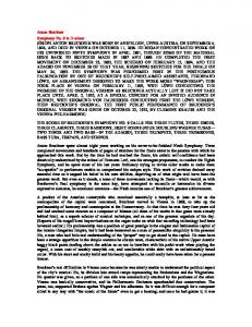
Figure 7. Performance of a 512-node Anton system versus chemical system size. Wallclock time for an entire time step and for various HTIS tasks is plotted as a function of the number of atoms in the chemical system. The large jump in simulation time around 45,000 atoms is due to the increase in the grid size required to maintain simulation accuracy. Data is from a cycle-based performance model calibrated to within 10% of the RTL. Server memory limitations restrict the cycle-based performance model to about 100,000 atoms, but Anton itself will be capable of simulating billions of atoms.
Peak performance (interactions/µs/chip) 25,600 1,500 122
column of Table 2 shows our estimates of the wallclock time spent by each MD platform performing particle-particle interactions. The Anton figure comes from our own RTL simulations. The Desmond figure is derived from a performance model that has been built from and validated against wall-clock simulation times. We have not listed a figure for NAMD, as its parallelization strategy does not lend itself to this kind of breakdown. The Blue Gene figure was calculated by halving the estimated time for Blue Gene to complete a time step, based on a recent report that Blue Gene spends 50% of its time on particle-particle calculations for a different chemical system [10, 11]. The MDGRAPE-3 figure was calculated using that group's performance model [25]. The GROMACS figure comes from profile runs we conducted. Despite the large potential for noise in these estimates, two things are clear: the HTIS computes particle-particle interactions more than two orders of magnitude faster than other systems, and Anton computes an entire time step in far less time than other systems spend on particle-particle interactions alone. While peak performance is a much-abused performance metric, it is indicative of the silicon area devoted to computational units in both generalpurpose and special-purpose solutions, and from this perspective serves as an illustrative architectural metric. Table 3 lists peak performance (measured in particle-particle interactions per microsecond per chip) for three different platforms. Custom hardware enables solutions that are both deep (each Anton PPIP is
28 stages deep and performs about 50 arithmetic operations per clock cycle) and wide (Anton has 32 PPIPs per ASIC). This results in on-chip parallelism far beyond the capability of general-purpose, programmable systems. Note that both special-purpose solutions (Anton and MDGRAPE-3) have orders of magnitude more peak performance than software running on general-purpose processors. The performance advantage of a special-purpose architecture is not threatened by Moore’s law, since the same technology that enables more cores on future general-purpose processors will also enable more special-purpose pipelines on future ASICs. Our last figure returns to a user-relevant dimension of performance: scaling with problem size. Figure 7 shows a breakdown of the wall-clock time for a single time step for chemical systems ranging from 20,000 to 100,000 atoms. These timings reflect settings we expect to use in a production environment; cutoffs and other parameters vary from system to system in a way that maintains the required computational accuracy while maximizing performance. It is clear that Anton’s performance achieves linear scaling over this range of system sizes. System balance is also largely independent of problem size; the HTIS
340
computation accounts for between one quarter and one third of the total time step across the entire range. Scaling to smaller problems, with time steps completed in less than 20 microseconds, is particularly noteworthy as systems of this size will be the first ones to be simulated over millisecond time scales.
nents are essential to the overall performance of Anton. Without them, the HTIS would be starved for data or blocked on output, greatly hindering Anton’s ability to actually perform MD calculations. The net effect of this systematically balanced and specialized engineering solution is that Anton should be able to perform MD simulations roughly two orders of magnitude faster than is currently possible, enabling simulations on millisecond time scales. It is our hope that the resulting tool will enable scientific discoveries that will increase understanding of biological systems and the nature of disease, and eventually pave the way for new therapies to improve health and quality of life.
5. Related Work The use of specialized hardware allows Anton’s HTIS to achieve a peak performance on range-limited pairwise particle interactions that is more than two orders of magnitude higher than a modern generalpurpose processor. Specialized hardware for MD has a surprisingly long history: the Delft machine [2], operational in 1982, implemented a 4 MHz arithmetic pipeline similar to one of our PPIPs. Other specialized hardware projects, e.g., FASTRUN [9], MD Engine [26], and MDGRAPE [16], have also accelerated the inner loop of MD calculations using the technology available at the time. Anton's HTIS updates the technology to 2008, but more importantly, it is the first to simultaneously address the limits imposed by parallel inter-chip communication and massively parallel on-chip computation using the combination of the NT algorithm and a direct product selection reduction architecture. The MDGRAPE project [16], which has produced several specialized ASICs for MD, allows computation of all interactions between two sets of particles, but the ASIC does not implement selection criteria. As a result, a substantial majority of the interactions computed by MDGRAPE represent redundant computation that would be excluded on Anton. Anton’s HTIS is also the first specialized hardware to accelerate the charge spreading and force interpolation parts of the grid-based electrostatic interactions, further increasing the portion of the computation that is accelerated by specialized hardware.
Acknowledgments The authors wish to extend their thanks to Joe Bank, Greg Lund and John Schomburg for valuable contributions to the work reported in this paper.
References [1] S. A. Adcock and J. A. McCammon, Molecular Dynamics: Survey of Methods for Simulating the Activity of Proteins, Chem. Rev., 106: 1589-1615 (2006). [2] A. F. Bakker and C. Bruin, Design and Implementation of the Delft Molecular-Dynamics Processor, in Special Purpose Computers, pp. 183-232 (Academic Press, San Diego, 1988). [3] K. J. Bowers, E. Chow, H. Xu, R. O. Dror, M. P. Eastwood, B. A. Gregersen, J. L. Klepeis, I. Kolossvary, M. A. Moraes, F. D. Sacerdoti, J. K. Salmon, Y. Shan, and D. E. Shaw, Scalable Algorithms for Molecular Dynamics Simulations on Commodity Clusters, in Proceedings of the 2006 ACM/IEEE Conference on Supercomputing (SC06), Tampa, Florida (2006). [4] K. J. Bowers, R. O. Dror, and D. E. Shaw, The Midpoint Method for Parallelization of Particle Simulations, J. Chem. Phys, 124: 184109 (2006).
6. Conclusion
[5] K. J. Bowers, R. O. Dror, and D. E. Shaw, Zonal Methods for the Parallel Execution of Range-Limited N-body Simulations, J. Comput. Phys., 221(1): 303-329 (2007).
Anton’s HTIS delivers unprecedented arithmetic performance on the most time consuming calculations in MD. The microarchitecture of the HTIS is designed to perform well at high levels of parallelism (i.e., only tens of atoms per node). This scalability is delivered through tight integration of particle memory, particle distribution and force reduction networks, match units, and dense computational pipelines. Beyond the HTIS’ specialized resources for the inner-loop computation, the Anton system includes a specialized, high-performance communication network and deploys a specialized flexible subsystem to handle the remaining computations. These compo-
[6] C. L. Brooks and D. A. Case, Simulations of Peptide Conformational Dynamics and Thermodynamics, Chem. Rev., 93: 2487-2502 (1993). [7] J. J. Dongarra, J. Du Croz , S. Hammarling, and I. S. Duff, A Set of Level 3 Basic Linear Algebra Subprograms, ACM Trans. Math. Soft., 16(1): 1-17 (1990). [8] Y. Duan and P. A. Kollman, Pathways to a Protein Folding Intermediate Observed in a 1-Microsecond Simulation in Aqueous Solution, Science, 282(5389): 740-744 (1998).
341
[9] R. D. Fine, G. Dimmler, and C. Levinthal, FASTRUN: A Special Purpose, Hardwired Computer for Molecular Simulation, Proteins: Struct. Funct. Genet., 11(4): 242-253, 1991 (erratum: 14(3): 421-422, 1992).
[21] Y. Shan, J. L. Klepeis, M. P. Eastwood, R. O. Dror, and D. E. Shaw. Gaussian Split Ewald: A Fast Ewald Mesh Method for Molecular Simulation, J. Chem. Phys., 122: 054101 (2005).
[10] B. G. Fitch, A. Rayshubskiy, M. Eleftheriou, T.J. Christopher Ward, M. Giampapa, M. C. Pitman, R. S. Germain, Blue Matter: Approaching the Limits of Concurrency for Classical Molecular Dynamics, in Proceedings of the 2006 ACM/IEEE Conference on Supercomputing (SC06), Tampa, Florida (2006).
[22] D. E. Shaw. A Fast, Scalable Method for the Parallel Evaluation of Distance-Limited Pairwise Particle Interactions, J. Comput. Chem., 26:1318-1328 (2005). [23] D. E. Shaw, M. M. Deneroff, R. O. Dror, J. S. Kuskin, R. H. Larson, J. K. Salmon, C. Young, B. Batson, K. J. Bowers, J. C. Chao, M. P. Eastwood, J. Gagliardo, J.P. Grossman, C. R. Ho, D. J. Ierardi, I. Kolossváry, J. L. Klepeis, T. Layman, C. McLeavey, M. A. Moraes, R. Mueller, E. C. Priest, Y. Shan, J. Spengler, M. Theobald, B. Towles, S. C. Wang, Anton: A Special-Purpose Machine for Molecular Dynamics Simulation, in Proc. 34th International Symposium on Computer Architecture (ISCA’07), 1-12, San Diego, CA, 2007.
[11] B. G. Fitch, A. Rayshubskiy, M. Eleftheriou, T.J. Christopher Ward, M. Giampapa, Y. Zhestkov, M. C. Pitman, F. Suits, A. Grossfield, J. Pitera, W. Swope, R. Zhou, S. Feller, and R. S. Germain, Blue Matter: Strong Scaling of Molecular Dynamics on Blue Gene/L, in Proceedings of the International Conference on Computational Science (ICCS 2006), V. Alexandrov, D. van Albada, P. Sloot, and J. Dongarra, Eds., Springer-Verlag, LNCS, 3992:846-854 (2006).
[24] M. Snir, A Note on N-Body Computations with Cutoffs, Theor. Comput. Syst., 37: 295-318 (2004).
[12] D. Frenkel and B. Smit, Understanding Molecular Simulation: From Algorithms to Applications, Second ed. (Academic Press, London, 2001).
[25] M. Taiji, T. Narumi, Y. Ohno, N. Futatsugi, A. Suenaga, N. Takada, A. Konagaya, Protein Explorer: A Petaflops Special-Purpose Computer System for Molecular Dynamics Simulations, in Proc. ACM/IEEE Conf. on Supercomputing (SC03), Phoenix, AZ, 2003.
[13] M. Karplus and J. A. McCammon, Molecular Dynamics Simulations of Biomolecules, Nat. Struct. Bio., 9(9): 646-652 (2002).
[26] S. Toyoda, H. Miyagawa, K. Kitamura, T. Amisaki, E. Hashimoto, H. Ikeda, A. Kusumi, and N. Miyakawa, Development of MD Engine: High-Speed Accelerator with Parallel Processor Design for Molecular Dynamics Simulations, J. Comput. Chem., 20(2): 185-199 (1999)
[14] J. S. Kuskin, C. Young, J.P. Grossman, B. Batson, M.D. Deneroff, R.O. Dror, and D. E. Shaw, Incorporating Flexibility in Anton, a Specialized Machine for Molecular Dynamics Simulation, , in Proc. 14th International Symposium on Computer Architecture (HPCA 2008), Salt Lake City, UT, 2008.
[27] D. van der Spoel, E. Lindahl, B. Hess, G. Groenhof, A. E. Mark, and H. J. C. Berendsen, GROMACS: Fast, Flexible, and Free, J. Comput. Chem., 26(16): 1701-1718 (2005).
[15] MD Benchmarks for Amber, CHARMM and NAMD, See http://amber.scripps.edu/amber8.bench2.html. [16] T. Narumi, Y. Ohno, N. Okimoto, T. Koishi, A. Suenaga, N. Futatsugi, R. Yanai, R. Himeno, S. Fujikawa, M. Taiji, and M. Ikei, A 55 TFLOPS Simulation of AmyloidForming Peptinds from Yeast Prion Sup35 with the SpecialPurpose Computer System MDGRAPE-3, in Proceedings of the 2006 ACM/IEEE Conference on Supercomputing (SC06), November 2006, Tampa, Florida. [17] J. C. Phillips, R. Braun, W. Wang, J. Gumbart, E. Tajkhorshid, E. Villa, C. Chipot, R. D. Skeel, L. Kalé, and K. Schulten, Scalable Molecular Dynamics with NAMD, J. Comput. Chem., 26(16): 1781-1802 (2005). [18] S. Plimpton, Fast Parallel Algorithms for Short-Range Molecular-Dynamics, J. Comput. Phys., 117(1): 1-19 (1995). [19] T. Schlick, R. D. Skeel, A. T. Brunger, L. V. Kalé, J. A. Board, J. Hermans, and K. Schulten, Algorithmic Challenges in Computational Molecular Biophysics, J. Comput. Phys., 151(1): 9-48 (1999). [20] M. M. Seibert, A. Patriksson, B. Hess, and D. van der Spoel, Reproducible Polypeptide Folding and Structure Prediction Using Molecular Dynamics Simulations, J. Mol. Biol., 354(1): 173-183 (2005).
342