How Data Transfer Modes and Synchronization Schemes Affect the Performance of a Communication System Based on Myrinet Rossen Dimitrov
[email protected]
Anthony Skjellum
[email protected]
Boris Protopopov
**
[email protected]
Department of Computer Science Mississippi State University Mississippi State, MS 39762 Box 9637
Abstract This paper presents a series of experiments for evaluating the influence of the interaction between Network Interfaces (NIs) and host computer systems on the performance of a messaging system based on Myrinet. Major points of interest are the data transfer between user buffers and NI local memory and the synchronization between host systems and NIs. The paper provides a taxonomy of various transfer modes and synchronization schemes, describes experiments for their performance evaluation, and analyzes the results on a specific platform as well as between different platforms. Furthermore, this paper points out the affects of the reviewed data transfer modes and synchronization schemes on the overall performance of Myrinet based message-passing systems and finally, proposes certain architectural solutions in future NICs for increasing the efficiency of their interaction with host computer systems. Keywords: network interface, data transfer modes, synchronization, interaction, messagepassing, performance, gigabit networks, Myrinet Tutorial Section Bypassing the Operating System, Memory Mapping, and Programmed I/O Modern high performance networks can transmit data at gigabit-per-second rates, introduce less than a microsecond of hardware latency, and have bit error probabilities in the **
Currently, with Mercury Computer Systems, Chelmsford, MA. Email address:
[email protected].
range of 10-15 [2]. At the same time, the computing power of workstations and personal computers is continuously growing. As a result, clusters of workstations using gigabit networks as interconnecting media quickly are becoming cost-effective platforms capable of performing intensive concurrent scientific computations, high bandwidth multimedia stream transfers, distributed database management, and time-critical tasks. In this new environment, traditional protocol stacks and message-passing models account for an intolerably high system overhead [1]. Often, the software overhead of a kernel call to the operating system for processing an incoming or outgoing message is higher than the time necessary for the network to transmit the message itself. Bypassing the Operating System A major source of performance gain in a message-passing system is reducing the role of the host Operating System (OS) in the actual data transmission and thus, minimizing the processing overhead on the critical data path. Bypassing the OS leads to a number of benefits: •
Lower latency – overhead associated with kernel calls is avoided;
•
Higher effective bandwidth – extra data copies are minimized;
•
Higher predictability – more precise scheduling of communication activities is possible. Common operating systems are difficult to describe with mathematical or probabilistic models. The software architecture of a messaging system that bypasses the OS is based on user libraries that implement functions for interacting with the NI adapter (Fig. A1). Among these functions are the following: forwarding messages, receiving messages, queue management, status reports, and synchronization. User Application Message-Passing Library OS Kernel Network Interface Adapter
User Space Kernel Space NI
Fig. A1. Software architecture of a messaging system bypassing OS.
Memory Mapping Memory mapping of network host adapter resources, namely, memory, control registers, and status registers, into user address space is a mechanism that allows user application processes to bypass the host OS and directly access and manipulate adapter’s resources. Some of the newest NI adapters can decode a range of addresses (up to a few megabytes). This range is divided into areas for different resources: SRAM, EEPROM, and registers. At the OS bootstrap, a network device driver maps the NI adapter address space into the system’s kernel address space. If requested from a user process, a library function performs an I/O control call to the network driver that maps the system memory region corresponding to the NI adapter space into the address space of the requesting process. When this sequence of operations is completed, user 2
processes can directly access and manipulate the network adapter (Fig. A2). Frequently, NI adapters are implemented as microprocessor systems [2] capable of executing custom control programs. Such programs in Myrinet are called Myrinet Control Programs (MCPs) [2]. So, for instance, one of the operations that a user process can perform with the NI adapter is to load a specific control program into the adapter’s memory. Another operation is copying user buffers into adapter’s local memory and then signaling the NI control program or FPGA to transmit this message to the network. Driver at Bootstrap NI Space Kernel Address Space User Address Space
RAM
ROM
Registers
User Calls Driver’s IO Control Routine
Fig. A2. Memory mapping of NI adapter resources into user address space.
Programmed I/O Programmed I/O is an approach for implementing a message-passing system where the host CPU is involved in data transfer operations as opposed to a system in which the data movement is performed by Direct Memory Access (DMA) engines residing either on the mother board of the host system or on the NI adapters. Myrinet NI adapters have such DMA engines [2] and offer several modes of Programmed I/O: •
The host CPU directly manipulates adapter’s send/receive registers (similar to working with parallel or serial ports);
•
The host CPU copies user buffers into the NI adapter’s memory and notifies the control program the control program running on the adapter;
•
The host CPU copies user data into an intermediate kernel copy block and informs the NI adapter to transfer data into local memory. In order to access the copy block residing in host memory, the NI adapter has to be equipped with a device capable of operating as a master on the host system bus. Such a device on the Myrinet NI adapters is the DMA engine. Although programmed I/O offers various solutions for flexible software architectures, it is a source of system inefficiency because host CPU cycles are used for communications purposes instead of for useful computation. Programmable NI adapters can unload host CPU from immediate data transfer operations and thus, provide for computation-communication
3
overlapping leading to a better host CPU utilization and consequently, increase of the overall system efficiency, assuming sufficient host memory-NI adapter bandwidth exists. In order to exploit the advanced hardware characteristics of the latest gigabit networking technologies, system communications software should employ new, efficient architectures. Bypassing the host OS, memory mapping, and programmed I/O are mechanisms that allow the design and implementation of such architectures. The particular use of these mechanisms may vary with the specific system environment but they all aim to achieve higher communications efficiency by reducing the processing overhead and the number of intermediate data copies. Introduction Myrinet is a gigabit network [2] widely used in clusters of workstations and embedded systems for high-performance concurrent computing. Currently, several message-passing systems based on Myrinet exist: Myricom API [2], Fast Messages (FM) [9], BDM/BDM Pro [6], Active Messages [3], GM [7]. They have certain features in common: memory mapping of Myrinet NI adapter (LANai adapter) resources into user space for bypassing host operating system, using a custom Myrinet Control Program (MCP), and to a different degree polling for synchronization, programmed I/O, and using LANai Direct Memory Access (DMA) engines. Among others, one major point of difference is the approach used for transferring data from user buffers to LANai memory. One of the goals of this paper is to demonstrate how the communication performance varies with the use of different data transfer modes, some of which are employed by the above mentioned systems. Comparison of these systems, however, is not within scope. Generally, there are two methods for synchronization between host systems and network adapters: synchronous and asynchronous. Representatives of these methods are, respectively, polling and hardware interrupts. This paper describes and compares two polling schemes for synchronization between LANai adapters and host CPUs. Together, the data transfer modes and the synchronization schemes reviewed here form a space of six different points in a twodimensional space of software architectures of Myrinet-based messaging systems. Experimental results for latency and bandwidth performance metrics are presented for each point of this space. Furthermore, the experiments are repeated on two distinct computer platforms. Although comparing and evaluating the absolute communications performance of these two platforms is outside the scope of this paper, it works to reveal specifics in the behavior of the interaction between Myrinet adapters and different host platforms that are critical for the architectural design of efficient multi-platform messaging systems. In the following sections, the paper specifies the data transfer modes and synchronization schemes selected for investigation here and describes the experimental environment, the host and Myrinet control programs, and the performance metrics. Then, the paper presents the experimental data and analyzes the results. Finally, proposals are offered for software and hardware architectural solutions for future programmable NI adapters and communications systems based on them. LANai Adapters LANai adapters are implemented as independent microprocessor systems based on the LANai processor [2]. LANai adapters have EEPROM and up to 1 Mbyte SRAM both accessible by the LANai processor through the local bus (L-bus). LANai memory appears from the external host system bus (E-bus) as a block of asynchronous memory [2]. There are three DMA engines 4
on LANai adapters: two for handling the traffic between adapter’s send/receive registers and its local memory and one that can operate as an E-bus master capable of transferring data between host system memory and LANai memory. In this paper, the term “DMA engine” refers to the LANai E-bus DMA engine, unless otherwise specified. Data Transfer Modes The flexible design of LANai adapters offers a variety of approaches for transferring data from user address space to the Myrinet physical medium. These approaches can be divided into two groups according to the mode in which the LANai adapter is used. In the first group of approaches, the host CPU directly accesses and manipulates the control, status, and interrupt registers of the LANai adapter. User processes can implement this mode of operation when the LANai adapter address space is mapped into the user address space (see the tutorial part). In this case, the LANai processor does not execute an MCP. As opposed to that, the approaches in the second group use MCPs. These MCPs may differ in functionality, as it will be shown later, but they all are responsible for draining the network and performing initial processing on the incoming messages as well as for sending user messages over the network. This paper examines data transfer modes from the second groups of approaches. When compared to the first group of approaches, they have the following benefits: •
Reduced system overhead;
•
Unloading the host CPU from immediate communications operations;
•
Increased likelihood for computation-communication overlapping, provided sufficient host memory - NI adapter bandwidth exists;
•
Better utilization of the NI adapter hardware resources;
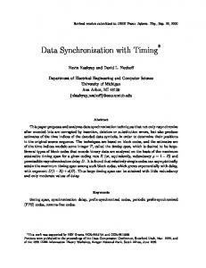
• Higher flexibility. In our study, we concentrate on the data path starting from the buffers in user address space and ending in the LANai memory (and vice versa). This data path is the critical performance factor of the interaction between host systems and NI adapters. Here, we investigate three different data transfer modes, as shown in Figure 1. In this figure, the dark arrows represent data transfers performed by the LANai DMA engine and light arrows represent User Buffer
User Buffer
User Buffer
User Space Kernel Space
Copy Block
LANai Memory
LANai Memory
(a)
(b)
LANai Memory
LANai
(c)
Fig. 1. Transfer modes: (a) Programmed I/O, (b) Programmed I/O and DMA using copy block, (c) DMA.
transfers performed by the host CPU. Dashed lines separate the different address spaces in which data may reside. In the programmed I/O transfer mode (Fig. 1.a), data is moved entirely by the 5
host CPU. When a user buffer is ready for transmitting, the user invokes a library function that copies data to the LANai memory and signals the MCP. After a procedure for synchronization, the MCP sends the buffer to the network. In receive mode, the MCP drains the network and puts an incoming packet in the LANai memory. The host CPU is then signaled and copies data from the adapter’s memory to the user buffer. This mode of data transfer is referred to as zero-copy transfer [2], although in fact, there is one copy in the LANai. The second data transfer mode uses an intermediate copy block residing in kernel space (Fig. 1.b). When a user process is ready to send a buffer it calls a library function to copy data in the copy block and then signals the MCP. The MCP initiates a DMA transfer, which brings the data into the local memory. Similarly, when a packet is received from the network, the MCP initiates a DMA transfer that moves received data in the copy block. A user library function then copies data to the user buffer. The second mode adds one extra data copy in host system memory. This extra copy is necessary because LANai DMA engine can access only contiguous pages pinned in physical memory [2]. For this reason, Myrinet device driver allocates the copy block as a kernel memory region at OS boot time. The copy block is guaranteed to occupy a memory region in permanently pinned contiguous physical pages. The third data transfer mode is depicted in Fig. 1.c. Here, when a user buffer is ready for sending, the user process simply signals the MCP which in turn initiates a DMA transaction and copies the data directly from the buffer to the LANai memory. In receive mode, the MCP receives a packet from the network and through the DMA engine forwards it to the destination user buffer. This transfer mode uses one intermediate copy in the LANai memory, as the first transfer mode does. As it was stated above, the LANai DMA engine operates with physical memory only. Therefore, user buffers should be permanently pinned in contiguous physical pages. Since neither one of the operating systems used in the experiments (Sun Solaris nor Microsoft Windows NT) supports user memory allocation with these constraints, for the purposes of the experiments, user buffers are located in a pinned copy block∗. In what follows, the three data transfer modes are referred as Mode1, Mode2, and Mode3, following Figure 1.a, 1.b, and 1.c, respectively. Synchronization Schemes The second component of the interaction between the host CPU and the LANai processor that is examined here is the synchronization between the two processors. In general, this issue is orthogonal to the data transfer modes and is evaluated separately. This is done by repeating the experiments implementing the three modes described in the previous section with two different synchronization schemes, so that the results and the conclusions about the two issues do not interfere. However, this assumption is valid at first order of approximation only, as it will be shown later in the paper. The data transfer mode and the synchronization scheme are major components of the interaction between host platforms and NI adapters and they both result in activities on the host system bus and LANai local bus, hence influencing each other. In a more precise model of the interaction, this influence should be taken into account. As opposed to the interrupt driven asynchronous methods for synchronization between the user process and the NI adapter, the synchronous methods can be implemented without the ∗
A new release of the “Mississippi State University memory mapped Myrinet device driver for PCI LANai 4.x adapters” [4] supports pinning of user memory pages on demand.
6
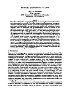
host operating system. In order to achieve higher flexibility and predictability of the experimental architectures, we choose to implement the synchronous approaches. Both synchronization schemes studied in this paper use polling for notification. The main difference between the two schemes is the form and location of the notification flags. In the first scheme (Fig. 2.a), all synchronization flags are located in the LANai memory. Consequently, both LANai processor and host CPU signal or detect completion of events by modifying or respectively polling the same synchronization flags. As a result, the number of cycles in which the LANai processor accesses its local memory can be reduced. This, in turn, may cause a slow down in the MCP progress because the access to the L-bus is arbitrated according to the following priority: E-bus, receive DMA, send DMA, LANai processor [8]. Host System CPU
Host System
Memory
CPU
System Bus Memory
Memory
System Bus
LANai
Memory
LANai Card
LANai
LANai Card
(a)
(b)
Fig. 2. Synchronization schemes: Synchronization flags (a) in LANai memory, (b) split in LANai and host memory.
In the second scheme (Fig. 2.b), the synchronization flags have the same semantics but each flag is split into two parts: one residing in the LANai memory and one in the host memory. Now, each processor polls on flags in its local memory, potentially cacheable, and updates both parts of a flag simultaneously when an event has occurred or completed. This scheme prevents the L-bus from excessive external accesses for polling. However, it requires that the LANai processor access the host memory for signaling the flags that reside there. A Myrinet adapter can access the host memory only through a DMA: the LANai DMA engine is the only device on the adapter equipped with an interface to the host E-bus, hence capable of accessing host memory [8]. Therefore, in order to implement the second synchronization scheme, for each flag update in host memory, the experimental MCPs, described in the next section, perform a sequence of operations for setting up the DMA transactions and checking status registers for completion. This sequence induces extra processing overhead and influences the performance results of the experiments using the second scheme. For clarity of the notation, similarly to the data transfer modes in the previous section, the synchronization schemes are named as Scheme1 and Scheme2 as depicted in Figure 2.a and 2.b. Description of the Experiments Experimental Environment and Network Topology Two different computer platforms were used for performing the experiments: •
Sun Ultra running Sun Solaris 2.5.1; 7
• PC with Pentium Pro CPUs running Microsoft Windows NT 4.0. The Myrinet hardware consisted of two double-speed 8-port switches, double-speed cables, and double-speed PCI and SBus LANai 4.1 adapters. Detailed description of the platforms and the network components is presented in Appendix A. Memory mapped Myrinet device drivers were used for the experiments: the Mississippi State University driver for the PCI adapters on the NT machines [2] and the Myricom driver for the SBus adapters on the Solaris machines [8]. The topology of the experimental environment is shown in Fig. 3.
SW 8
Sun Ultra 2
PC1
SW 8
PC2
Sun Ultra 1
Fig. 3. Network topology of the experiments.
Myrinet Control and Host Programs The MCPs used for the experiments implement a simple protocol with no support of reliability, ordering, fragmentation, and reassembly; an error-free transmission is assumed. Packets consist of a packet header with three fields: 0 to 8 byte source route, 4 byte packet type, 4 byte payload length; and packet payload carrying user data. In order to reduce the processing overhead, the MCPs perform minimal functionality and does not implement any efficiency optimizations like overlapping send/receive DMA with E-bus/L-bus DMA; hence, each transfer begins after a previous transfer has completely finished. Although such optimizations are possible and desirable, their use does not change the nature of the host system – LANai adapter interaction in principle and, therefore, the experiments and conclusions presented in this paper preserve their validity. The experimental programs running on the host platforms first map the LANai adapter’s address space into user space and then load the appropriate MCP into LANai memory. The programs perform a sequence of ping-pong tests with messages of different sizes. A message of size L is sent from PC1 to PC2 and then returned back to PC1. This procedure is repeated N times. The time T measured as the difference between the moments at which the last and the first iterations take place is divided by N and thus, the round trip time T RT of the message is obtained. The source code for the host programs is essentially identical for both platforms. Performance Metrics The two performance metrics used in this project are bandwidth and one-way latency. The one-way latency is computed as half of the round trip time, i.e., TRT/2. The bandwidth is obtained as L/TRT. The length of the payload of the packets vary from 0 to 32,768 bytes. Even with zero-length payload, a certain amount of data is transmitted over the network – the packet 8
header. In the topology used for the experiments (Fig. 3), the header length is 10 bytes, 2 for the source route, 4 for the packet type, and 4 for the payload length. The maximum payload length is at 32,768 bytes because for this packet size the bandwidth curves saturate. Since no fragmentation and reassembly is supported, the length of user messages is restricted to the maximum payload length (32,768 bytes). In the next section, the figures represent the dependence of the bandwidth and latency on the message size (packet payload). Each figure contains a pair of charts presenting the bandwidth and latency measurements of the three data transfer modes for one of the synchronization schemes (Scheme1 or Sheme2). Similar figures are provided for the two different platforms investigated. Experiments* The goal of the work described here is to examine the behavior of three data transfer modes (Fig. 1) and two synchronization schemes (Fig. 2) in a Myrinet messaging system. It is not an objective of this paper to compare the absolute performance of the two experimental platforms, neither to investigate the influence of the network topology, nor the number of intermediate network switches between the end nodes. Before presenting the measurements of the experiments, a brief introduction of some of the specific platform performance parameters is necessary. Two preliminary measurements on each of the computer platforms were conducted: •
bandwidth of host CPU transactions between host and LANai memory (the host CPU is master on the host system bus);
•
bandwidth of the LANai DMA engine transactions between host and LANai memory (the LANai DMA engine is master on the host system bus). It should be noted that these operations are composed of two transfers – first reading a host or LANai memory address and storing its content in the CPU or DMA engine internal registers and then storing this value respectively in LANai or host memory. For this reason, the numbers presented below should not be interpreted as absolute throughputs of the host system bus, host memory bus, or LANai local bus. The main purpose of these measurements was to investigate the parameters of data transfers over the host system bus (PCI for the PCs and SBus for the Sun Ultras) in different modes as well as the performance of the LANai DMA engine on different boards. Here, only the maximum numbers of the two experiments are presented: • host CPU master: host -> LANai memory: on PCI = 88.1 MB/s, on SBus = 73.2 MB/s; LANai -> host memory: on PCI = 14.5 MB/s, on SBus = 48.7 MB/s. • LANai DMA engine master: host -> LANai memory: on PCI = 113.3 MB/s, on SBus = 49.0 MB/s; LANai -> host memory: on PCI = 122.5 MB/s, on SBus = 65.9 MB/s. These numbers show that the host CPU transactions that originate from the host memory are faster than the ones that originate from the LANai memory. Similarly, the transactions performed by the LANai DMA engine are faster when their source is in the LANai memory than the ones having as a source the host memory. Another interesting point to note is that although the transactions are symmetrical, the LANai DMA engine on the PCI bus substantially outperforms the host CPU. This is not so obvious for the SBus LANai DMA engine. Lastly, the *
The exact numbers of all experimental executions are presented in Appendix B. 9
transactions with the host CPU master on the PCI bus show a large imbalance between the two directions. The “read” from the LANai memory operation is about six times slower (14.5 vs. 88.1 MB/s) than “write” to the LANai memory operation. This behavior is attributed to the specific PCI chipset of the experimental PC platforms (Natoma 440FX). Experiments on the PC platforms Figure 4 summarizes the bandwidth and latency measurements of the three modes of data transfer, namely, Mode1, Mode2, and Mode3 (Fig.1) using synchronization Scheme1 (Fig.2). The latency can be represented as a sum of two components: overhead latency and bandwidth latency. Overhead latency is the time spent on system overhead while the bandwidth latency depends solely on the bandwidth of the data transmission over the network. For messages longer than 32 bytes, the latency in the experimental messaging system is dominated by the bandwidth latency and in order to reveal the influence of the NI adapter - host system interaction only, the charts represent only the latency of messages with length in the range 0 to 32 bytes.
40.0
Latency [us]
Bandwidth [MB/s]
50.0
30.0 20.0 10.0 0.0 0
8
32
128
512
2k
8k
32k
16.0 14.0 12.0 10.0 8.0 6.0 4.0 2.0 0.0
Mode1 Mode2 Mode3
0
4
8
16
32
Message size [bytes]
Message size [bytes]
Fig. 4. Bandwidth and latency of the data transfer modes on a PC with synchronization Scheme1.
Mode 3 achieves about four times higher bandwidth than Mode1. The bandwidth of Mode1 is limited by the throughput of the CPU host transactions to the LANai memory as described in the preliminary measurements earlier in this section. For messages less then 512 bytes Mode2 performs as well as Mode3 but it cannot exceed 35MB/s and for messages longer than 2,048 bytes certain performance degradation occurs. The explanation of this behavior is subject to further experiments and analyses. This particular behavior demonstrates the complexity of the host system – NI adapter interaction and the need for its in-depth study. Mode3 outperforms the other two modes; it shows both the lowest latency and the highest bandwidth. In general, latency is not significantly affected by the specific data transfer modes while the bandwidth is greatly affected. One reason is that, as opposed to Mode1, both Mode2 and Mode3 do not use the operations that include host CPU transactions to the LANai memory, whose bandwidth is limited to 14 MB/s. Figure 5 represents the results from the experiments with synchronization Scheme2. The maximal values of the bandwidth of the three transfer modes are the same with the two synchronization schemes. Scheme2, however, reaches the maximum for higher message sizes. The reason for this is clearly seen from the latency chart – Scheme2 adds 0.5 to 2.5 microseconds to the latency for each data transfer modes. This additional latency can be attributed to the extra operations needed for the LANai processor to access the flags residing in host memory. This additional latency increases the round-trip time and, hence reduces the 10
effective bandwidth of messages with length less than the point of saturation. In general, the idea for the second synchronization scheme emerged as a means to unload the LANai local bus from the polling cycles of the host CPU, and it was evident from the beginning that only the bandwidth could benefit from this synchronization scheme.
40.0
Latency [us]
Bandwidth [MB/s]
50.0
30.0 20.0 10.0 0.0 0
8
32
128
512
2k
8k
32k
18.0 16.0 14.0 12.0 10.0 8.0 6.0 4.0 2.0 0.0
Mode1 Mode2 Mode3
0
4
8
16
32
Message size [bytes]
Message size [bytes]
Figure 5. Bandwidth and latency of the data transfer modes on a PC with synchronization Scheme2.
The comparison of the performance metrics as depicted in Figures 4 and 5 shows that Mode1 with Scheme1 is the most efficient combination. It should be noted, however, that the user buffers in Mode1 are in the copy block, not in a random location in the virtual address space. In a real messaging system, additional provisions for implementing this data transfer mode are required. For instance, a buffer allocated in the user address space should be passed to a kernel mode routine for translation into physical addresses and pinning in the physical memory. This operation will inevitably cause an additional overhead. In case of persistent operations [5], user buffers might be reused, so that the overhead can be introduced in a setup stage and through amortization may not significantly affect the performance of the actual communication. Another change required in the messaging system would be the need for a module that handles the transfer of noncontiguous memory pages. This is necessary because the LANai DMA engine can operate only with contiguous physical pages. This copy block requirement is guaranteed by the Myrinet device driver that allocates the copy block at OS boot time. These extra operations will incur additional processing overhead, which will change the performance results to a certain degree. Experiments on the Sun Ultra platforms The results from the experiments on the Sun Ultra machines are presented in the same way as the results from the PCs. Figure 6 shows results from the bandwidth and latency measurements of the three data transfer modes with Scheme1 while Figure 7 presents the results with Scheme2. The performance of the three data transfer modes on the Sun Ultra platforms exhibit a different from the PCs behavior. Here, the highest bandwidth is achieved by Mode1. Both Mode2 and Mode3 demonstrate similar characteristics, hence the extra intermediate data copy in the copy block does not influence the bandwidth notably. Another interesting feature of Figures 6 and 7 is that the curves of the bandwidth cross each other at message lengths of about 2,048 bytes. So, under certain conditions both the modes with DMA (Mode2 and Mode3) and the mode without DMA (Mode1) might be optimal in terms of bandwidth. Hence, a multi-mode implementation of the messaging system may lead to the highest performance gain. 11
30.0 Latency [us]
Bandwidth [MB/s]
35.0
50.0 45.0 40.0 35.0 30.0 25.0 20.0 15.0 10.0 5.0 0.0
25.0 Mode1
20.0
Mode2
15.0
Mode3
10.0 5.0 0.0
0
8
32
128
512
2k
8k
0
32k
4
8
16
32
Message size [bytes]
Message size [bytes]
Fig. 6. Bandwidth and latency of the data transfer modes on a Sun Ultra with synchronization Scheme1.
The latencies of the three modes for zero-length messages (packets contain only 10-byte long headers) are similar. However, the latency of Mode1 grows quickly even for small message sizes. From this observation and from the bandwidth chart in Figure 6, it can be concluded that the communication latency on the Sun platforms is dominated by the bandwidth latency for smaller messages than on the PCs; hence the system overhead is lower. On these platforms, a firm conclusion about the best performing mode could not be made. The behavior depicted in the bandwidth sections in Figures 6 and 7 should, however, be taken into account at the design phase of a messaging system. Investigation of parameters such as expected system load and maximum packet size becomes important for determining the data transfer modes used in the system. The comparison of the bandwidths of Mode2 and Mode3 with Scheme1 (Fig.6) and Scheme2 (Fig.7) shows that the second scheme leads to an increase of about 2 MB/s of the maximum bandwidth. As expected, Scheme2 increases the one way latency – with about 2 microseconds on average for the three data transfer modes. Again, on the Sun Ultra platforms, it could not be stated firmly what synchronization scheme performs better. Here, it should be restated that Scheme2 requires additional DMA operations for updating the synchronization flags in host memory, which results in an extra processing overhead.
40.0
Latency [us]
Bandwidth [MB/s]
50.0
30.0 20.0 10.0 0.0 0
8
32
128
512
2k
8k
32k
40.0 35.0 30.0 25.0 20.0 15.0 10.0 5.0 0.0
Mode1 Mode2 Mode3
0
4
8
16
32
Message size [bytes]
Message size [bytes]
Fig. 7. Bandwidth and latency of the data transfer modes on a Sun Ultra with synchronization Scheme2.
12
The experiments presented in this paper made one simplification: user buffers in Mode3 were allocated in the pinned copy block, not in a random location in the virtual space of the host OS. Consequently, two procedures, potentially adding extra overhead were not accounted for: 1) dynamic pinning of user buffers in physical memory, and 2) multiple DMA transactions needed for transferring the non-contiguous physical pages of the user buffers. For the purposes of this project these two procedures do not significantly affect the experiments and the conclusions but they should be taken into account in a real messaging system. Analysis, Lessons Learned, and Future Work In this paper, two components of the interaction between a Myrinet NI adapter and a host system were considered. These two components are the mode of data transfer between user buffers and LANai memory and the synchronization scheme between the host CPU and LANai processor. The mode of data transfer between user space and LANai memory is an important component of a communication system based on Myrinet. The end-to-end bandwidth is to a great degree influenced by the hardware capabilities of the host platform (especially the system bus) and the way data is moved to/from the LANai memory. On the two experimental platforms, the behavior of the three transfer modes was different. On the PCs, the modes with DMA outperform the mode with direct copying. This is valid even in the case when an intermediate copy block is used and extra data copy is made. The main reason for this difference in the bandwidth performance between the DMA on non-DMA modes is the limitation on the maximum throughput of the memory operations to the LANai memory initiated by the host CPU. Apparently, the difference between the PCI write throughput (88 MB/s) and read throughput (14 MB/s) is a significant one and it imbalances the communication system. The performance of the end-to-end communication system is clearly bound by the component with the lowest bandwidth (in this case, moving data from the LANai memory to the host memory by the host CPU at the receive side). The performance comparison of the three data transfer modes on the Sun platforms shows different results. On Suns, Mode1 achieves the highest bandwidth. This, however, is valid for relatively long packet sizes. For small packet sizes, the DMA modes perform better. So, depending on the specific requirements either one of the three methods could be successfully used. The different behavior of the data transfer modes on the two experimental platforms (PC, Sun) can be explained with the differences in the system bus (PCI, SBus) throughput, the performance of the LANai DMA engine on the different adapters, and the throughput of the read/write operations to the LANai memory when the LANai adapter is a target device and CPU is the master on the host system bus. An interesting combination of two data transfer modes (a mixed mode) might be achieved if one of the three modes is used on the send side and another one on the receive side. An experiment with such an asymmetrical architecture was conducted on the PC platforms. FM [9] uses similar approach. We used Mode1 (Fig.1.a) on the send side and Mode2 (Fig.1.b) on the receive side. Figure 8 demonstrates the measurements of the bandwidth experiments using the asymmetrical data transfer mode compared with the symmetric implementations of Mode1 and Mode2. The resulting architecture achieves two improvements: 1) it avoids the bandwidth limitation of the LANai memory – host memory transfer performed by the host CPU in Mode1, and 2) avoids the performance degradation of Mode2.
13
Bandwidth [MB/s]
50.0 40.0 Mode1 30.0
Mode2
20.0
Mixed
10.0 0.0 0
8
32
128
512
2k
8k
32k
Message size [bytes]
Fig. 8. Bandwidth of Mode1, Mode2 and Mixed Mode on PCs with Scheme1.
As opposed to bandwidth, one-way latency is not significantly influenced by the transfer modes. The differences in latency of the three modes are in the range of 1-2 microseconds (10 15%). Since the variations in bandwidth are higher (up to 100% or more) the final performance evaluation of the transfer modes depends mostly on their bandwidth capabilities. The two synchronization schemes, with notification flags in LANai memory and with split flags, show similar performance. The synchronization scheme with split flags was proposed to provide functionality that leads to a better balance of the memory accesses to the host and LANai memory, and thus increase the bandwidth. However, except in the case of Mode2’s bandwidth on PCs, the experiments show that the second scheme, does not lead to a performance gain; on the contrary, it introduces some additional overhead and increases the latency (about 12 microseconds). Apparently, the LANai adapters used in the experiments succeed processing the incoming and outgoing packets as well as making progress in the MCP while the host CPU is polling the LANai memory. Since the second synchronization scheme requires more complex software implementation, the first scheme should be generally considered better. Another perspective of the experiments presented in this paper is the influence of the amount of processing performed by the LANai adapter on the latency. The MCP that implements Mode1 has the most limited functionality. Mode2 and Mode3 MCPs are more complex – they perform not only the front message processing but also move data between the host and LANai memory. From the results presented above, it can be seen that in most cases, Mode1 shows the lowest latency. However, from another point of view, Mode2 and Mode3 reduce the processing overhead of the host CPU and thus, can provide for higher degree of computation-communication overlapping. We can generalize that there is a trade-off between the end-to-end latency and the degree of overlapping (reducing the system overhead). One explanation of this trade-off is that usually, NI adapters are based on processors that are behind the leading edge of the microprocessor technologies used in the host systems and thus, delegating more responsibilities to the NI adapters will add some latency. We can make the following summary from the experimental results and of the above analysis: •
The interaction between NI adapters and host systems is a complex process;
•
Different platforms have different optima results;
•
Asymmetrical architectures on a single platform may be feasible; 14
•
Bandwidth is the more important factor than latency;
•
Software architecture has to be flexible enough to cope with specific characteristics of different hardware host platforms and NI adapters which are continuously evolving;
•
A trade-off between processing overhead and latency exists;
•
Bypassing host OS is a significant factor for increasing the communications efficiency. Three hardware changes in the architecture of the Myrinet NI adapters can reasonably be proposed. First, scatter/gather functionality of the LANai DMA engine is critical for implementing a number of efficient solutions. Common operating systems (e.g., Windows NT and Solaris) do not offer allocation of user buffers in contiguous physical pages. A pinned buffer will be scattered over a number of physical pages. Consequently, a separate DMA transaction will be required for each non-contiguous page. The scatter/gather mode will allow the LANai DMA engine to transfer all pages (or a large number of them) with one transaction, with concomitant improvement in performance. Another application of the scatter/gather mode is the preparation of a packet for sending. Usually, packet headers are generated by the system software and are not physically attached to the user data that forms the packet payload. Single gather DMA transaction can send the packet to the network as a whole entity. The second hardware optimization we propose is an interface between the L-bus and the E-bus that will allow the LANai processor to access directly the host memory. This feature will enable more flexible synchronization schemes, as was discussed in the paper. Finally, support for a “chained DMA” capability would allow apparently direct DMA from the processor cutting through the network card, and appearing on the network. This would complement support for gather/scatter DMA. Evidently, support for a more general DMA register structure would be required. This does not appear to be a difficult modification to the current architecture. The newest trends in the area of high performance concurrent computing in distributed environments based on gigabit networks suggest numerous directions for future work. Here, we list some of them: •
Developing flexible message-passing systems that exploit the specific characteristics of the underlying platforms;
•
Optimizing operating systems for high performance communications purposes, including higher predictability;
•
Devising thinner and more optimal protocol stacks;
•
Moving more functions to the physical and data-link network layers, functions like: reliability, flow control, and message ordering;
•
Developing mechanisms for increasing the level of protection and security.
Conclusions This paper presented a study on the complex interactions between Myrinet network interface adapters and two types of host platforms. We investigated a two-dimensional design space formed by the synchronization schemes and data transfer modes between user buffers and LANai memory on each of the two experimental platforms. We demonstrated that the detailed 15
architecture of a Myrinet-based communications software determines to a great extent the overall performance of the networked system and we presented a systematic approach for evaluating existing and guiding the design of future software systems for Myrinet or other network interfaces. We determined that bandwidth is more greatly impacted by the detailed design considerations explored than is latency. We also pointed out a set of mechanisms critical for achieving efficient communications on gigabit networks: bypassing the host operating system, intelligent programmable network adapters capable of accessing host memory, programmed I/O, and memory mapping of network adapter resources into user space. Finally, this paper proposed hardware changes in LANai adapters that potentially lead to more flexible software architectures and stated directions for future work in this area. The area of programmable gigabit networks is an important, and likely to continue to grow. The ability to program the network, and thereby provide hardware threads of execution for certain network (and in future user) threads of control, continues to be important, and subject to much further exploration. In order to achieve the next revolutionary step in this area, we look forward to Network Interfaces incorporating multi-die state-of-the-art high MIPS processors, quickly retargetable field-programmable gate arrays (FPGAs), and banks of transfer engines, to be complemented by network and bus fabric monitoring so that the complex systems can be interpreted with a finer degree of accuracy, while permitting better tuning. This will clearly be complemented by switches and network fabrics that bring to bear basic quality of service appropriate to the high-speed environments, such as predictable end-to-end delay.
16
References 1. Basu, A., V. Buch, W. Vogels, T. von Eicken, U-Net: A User-Level Network Interface for Parallel and Distributed Computing, Proceedings of the 15th ACM Symposium on Operating Systems Principles (SOSP), Copper Mountain, Colorado, December 3-6, 1995 2. Boden, N.J., D. Cohen, R.E. Felderman, A.E. Kulawik, C.L. Seitz, J.N. Seizovic, and W.K. Su, Myrinet: A Gigabit-per-Second Local Area Network, IEEE Micro, Vol. 15, No.1, Feb. 1995. 3. Culler, David, Rich Martin, Lock Liu, and Vikram Makhija. LANai Active Messages. Available from http://now.cs.berkeley.edu/AM/lam_release.html (30 July 1997). 4. Dimitrov, Rossen. A Windows NT Kernel-Mode Device Driver for PCI Myrinet LANai 4.x Interface Adapters. M.S. Project Report, Mississippi State University,1997, http://www.cs.msstate.edu/publications/theses_and_dissertations.html 5. Gropp, William, Ewing Lusk, and Anthony Skjellum, Using MPI, MIT Press, 1994. 6. Henley, Gregory. J, Thomas P. McMahon, Anthony Skjellum, and Nathan E. Doss. Design of the BDM Family of Myrinet Control Programs. http://erc.msstate.edu/labs/hpcl/papers/ bdm_family_design.ps, 1998 7. Myricom, GM Documentation, Available from http://www.myri.com/GM/doc/gm_toc.html (10 February 1998). 8. Myricom, LANai 4.X Documentation, http://www.myri.com/myrinet/products/ documentation/mug/development/LANai4.X.doc (12 May 1996). 9. Pakin, Scott, Vijay Karamcheti, and Andrew Chien. Fast Messages: Efficient, Portable Communication for Workstation Clusters and MPPs. IEEE Concurrency, Vol. 5, No. 2, April - June 1997
17
Appendix A Description of the Experimental Platforms
1. Sun Ultra 1.1 Sun Ultra 1 (OS: Sun Solaris 2.5.1) CPU: 1 x UltraSPARC 167MHz Memory: 64 Mbytes Bus: SBus 1.2 Sun Ultra 2 (OS: Sun Solaris 2.5.1) CPU: 2 x UltraSPARC 2 200MHz Memory: 256 Mbytes Bus: SBus 2. Personal Computers 2.1 PC1 (OS: Microsoft Windows NT 4.0) CPU: 2 x Pentium Pro 200MHz (Stepping 7) Memory: 128 Mbytes Bus: PCI, 32bit @ 33MHZ Chipset: Natoma 440FX 2.1 2.2 PC2 (OS: Microsoft Windows NT 4.0) CPU: 2 x Pentium Pro 200MHz (Stepping 9) Memory: 128 Mbytes Bus: PCI, 32bit @ 33MHZ Chipset: Natoma 440FX 3. Myrinet Switches: Adapters:
M2F-SW8 M2F-PCI32A (256 KB memory) M2F-SBus32A (256 KB memory) Cables:M2F-CB25
18
Appendix B Tables with the Experimental Results Used in the Paper 1. Bandwidth of the transactions host memory – LANai memory when the LANai DMA engine is a master on the host system bus PCI and SBus Size 4 8 16 32 64 128 256 512 1024 2048 4096 8192 16384 32768 65536 131072
to LANai 1.5 3.7 6.9 13.0 23.7 40.1 58.8 79.9 95.9 106.2 108.6 111.6 112.2 113.2 113.2 113.3
to Host 2.2 4.1 8.3 15.0 26.8 43.8 66.4 86.7 102.2 113.8 117.4 120.8 122.4 122.3 122.3 122.5
Size 4 8 16 32 64 128 256 512 1024 2048 4096 8192 16384 32768 65536 131072
Table 1. PCI bus
to LANai 1.9 2.6 4.2 6.7 10.7 18.3 27.0 34.7 40.7 44.2 46.7 47.9 48.5 48.9 49.0 49.0
to Host 2.7 4.0 5.4 8.2 15.9 29.5 41.6 50.9 57.5 61.7 63.9 65.1 65.7 66.0 66.2 65.9
Table 2. SBus
2. Bandwidth and latency of Mode1, Mode2, and Mode3 with synchronization Scheme1 on PC platforms. Size 0 4 8 16 32 64 128 256 512 1024 2048 4096 8192 16384 32768
Mode1 0.0 0.9 1.7 3.3 5.1 7.2 8.8 9.8 11.0 11.0 11.0 11.0 11.0 11.0 11.0
Mode2 0.0 0.8 1.5 3.2 5.6 11.0 17.0 26.0 35.0 35.0 35.0 33.0 27.0 25.0 24.0
Mode3 0.0 1.0 2.0 3.8 7.3 13.0 21.0 29.0 36.0 41.0 44.0 45.0 45.0 45.0 45.0
Size 0 4 8 16 32 64 128 256 512 1024 2048 4096 8192 16384 32768
Table 3. Bandwidth
Mode1 12.2 12.7 13.1 13.8 14.7 18.7 25.0 38.5 65.7 120.7 229.1 446.3 881.5 1752.1 3491.4
Mode2 11.1 12.5 12.5 12.9 13.6 15.2 17.8 24.0 35.2 58.2 104.3 207.3 472.3 1014.0 2069.9
Table 4. Latency
19
Mode3 10.6 11.6 11.7 12.0 12.3 12.9 14.6 17.9 25.1 39.4 68.1 127.1 243.9 478.3 946.6
3. Bandwidth and latency of Mode1, Mode2, and Mode3 with synchronization Scheme2 on PC platforms.
Size 0 4 8 16 32 64 128 256 512 1024 2048 4096 8192 16384 32768
Mode1 0.0 0.5 1.0 2.1 4.0 6.5 8.3 9.4 10.0 11.0 11.0 11.0 11.0 11.0 11.0
Mode2 0.0 0.6 1.2 2.3 4.6 8.3 14.0 21.0 29.0 33.0 34.0 34.0 34.0 34.0 34.0
Mode3 0.0 0.6 1.2 2.3 4.7 8.3 15.0 23.0 31.0 38.0 42.0 44.0 45.0 45.0 45.0
Size 0 4 8 16 32 64 128 256 512 1024 2048 4096 8192 16384 32768
Table 5. Bandwidth
Mode1 12.7 13.3 14.0 15.2 16.5 19.5 26.0 39.9 67.0 121.3 229.9 447.6 883.0 1753.5 3493.7
Mode2 14.7 15.9 15.9 16.0 16.3 17.9 21.5 27.2 38.8 62.9 110.8 209.1 413.8 816.0 1612.6
Mode3 14.1 15.1 15.2 15.2 15.6 16.4 17.9 21.1 28.2 42.6 71.3 130.3 246.6 479.2 945.4
Table 6. Latency
4. Bandwidth and latency of Mode1, Mode2, and Mode3 with synchronization Scheme1 on Sun Ultra platforms. Size 0 4 8 16 32 64 128 256 512 1024 2048 4096 8192 16384 32768
Mode1 0.0 0.6 0.9 1.0 1.2 3.0 4.7 6.3 12.0 21.0 31.0 37.0 44.0 48.0 49.0
Mode2 0.0 0.8 1.5 2.2 4.2 8.2 13.0 19.0 24.0 28.0 30.0 31.0 32.0 32.0 32.0
Mode3 0.0 0.9 1.8 2.6 5.1 9.7 16.0 22.0 26.0 29.0 30.0 31.0 32.0 32.0 32.0
Size 0 4 8 16 32 64 128 256 512 1024 2048 4096 8192 16384 32768
Table 7. Bandwidth
Mode1 9.8 13.3 16.8 23.8 33.3 28.5 36.4 52.2 57.4 73.8 109.5 188.1 336.5 637.9 1243.4
Mode2 10.4 11.2 12.5 14.5 16.4 16.8 20.5 28.9 42.3 73.5 128.0 242.3 483.4 926.5 1891.5
Table 8. Latency
20
Mode3 10.8 10.6 11.9 13.1 13.9 15.3 17.9 24.1 36.1 60.2 108.1 203.6 395.0 778.2 1543.8
5. Bandwidth and latency of Mode1, Mode2, and Mode3 with synchronization Scheme2 on Sun Ultra platforms. Size 0 4 8 16 32 64 128 256 512 1024 2048 4096 8192 16384 32768
Mode1 11.2 14.8 18.2 25.1 34.7 29.8 37.8 53.4 54.2 77.4 113.0 186.9 340.4 639.3 1277.2
Mode2 12.9 15.2 16.2 18.1 20.4 21.6 25.1 32.3 45.3 71.1 121.2 225.2 436.5 850.4 1700.5
Mode3 12.9 15.2 16.2 18.1 20.4 21.6 25.1 32.3 45.4 71.0 122.8 227.8 432.8 840.5 1706.0
Size 0 4 8 16 32 64 128 256 512 1024 2048 4096 8192 16384 32768
Table 5. Bandwidth
Mode1 0.0 0.5 0.8 1.0 1.2 3.1 4.8 6.6 14.0 21.0 30.0 39.0 44.0 48.0 48.0
Mode2 0.0 0.5 1.1 1.9 3.0 6.3 11.0 17.0 24.0 28.0 31.0 33.0 34.0 34.0 34.0
Table 6. Latency
21
Mode3 0.0 0.5 1.1 1.9 3.0 6.3 11.0 17.0 24.0 28.0 31.0 32.0 33.0 34.0 34.0