Hindawi Publishing Corporation International Journal of Reconfigurable Computing Volume 2016, Article ID 5340318, 12 pages http://dx.doi.org/10.1155/2016/5340318
Research Article How to Efficiently Reconfigure Tunable Lookup Tables for Dynamic Circuit Specialization Amit Kulkarni and Dirk Stroobandt ELIS Department, Computer Systems Lab, Ghent University, Sint-Pietersnieuwstraat 41, 9000 Ghent, Belgium Correspondence should be addressed to Amit Kulkarni;
[email protected] Received 27 October 2015; Accepted 2 March 2016 Academic Editor: Fernando Pardo Copyright © 2016 A. Kulkarni and D. Stroobandt. This is an open access article distributed under the Creative Commons Attribution License, which permits unrestricted use, distribution, and reproduction in any medium, provided the original work is properly cited. Dynamic Circuit Specialization is used to optimize the implementation of a parameterized application on an FPGA. Instead of implementing the parameters as regular inputs, in the DCS approach these inputs are implemented as constants. When the parameter values change, the design is reoptimized for the new constant values by reconfiguring the FPGA. This allows faster and more resource-efficient implementation but investigations have shown that reconfiguration time is the major limitation for DCS implementation on Xilinx FPGAs. The limitation arises from the use of inefficient reconfiguration methods in conventional DCS implementation. To address this issue, we propose different approaches to reduce the reconfiguration time drastically and improve the reconfiguration speed. In this context, this paper presents the use of custom reconfiguration controllers and custom reconfiguration software drivers, along with placement constraints to shorten the reconfiguration time. Our results show an improvement in the reconfiguration speed by at least a factor 14 by using Xilinx reconfiguration controller along with placement constraints. However, the improvement can go up to a factor 40 with the combination of a custom reconfiguration controller, custom software drivers, and placement constraints. We also observe depreciation in the system’s performance by at least 6% due to placement constraints.
1. Introduction An ability to modify some parts of the logic blocks of an FPGA while the rest remains active is called partial run-time reconfiguration and has been commercially available for quite a while through the Xilinx partial reconfiguration (PR) flow [1]. Members of our research group developed a technique called Dynamic Circuit Specialization (DCS) which is a partial reconfiguration technique tailored to parameterized applications [2]. A parameterized application contains a set of inputs for which some of the input values change much less frequently than the other inputs. The infrequently changing inputs are called parameters. DCS uses the run-time reconfiguration technique to specialize the parameterized design depending on the values of the infrequently changing inputs (parameters). Hence for every change in the parameter value, a new specialized bitstream is generated and the FPGA is reconfigured with the specialized bitstreams. Because the
actual reconfiguration bitstream is computed at run-time instead of at compile-time, DCS allows wider applicability of PR for implementation with a lot of different possible implementation variants. Our experiments for conventional DCS implementation on a self-reconfigurable platform [3] have shown the Hardware Internal Configuration Access Port (HWICAP) to be a main bottleneck for the reconfiguration speed, since its throughput is not high enough to match with the speed of the embedded processor used during the reconfiguration process. However, experiments described in [4] have shown that the bottleneck depends on the experiment setup and the different components that participate during the reconfiguration process. In the conventional implementation of a DCS system, the Xilinx HWICAP is used as a reconfiguration controller. The HWICAP driver function “XhwIcap setClb bits” is used to reconfigure the truth table entries of a single Lookup
2
International Journal of Reconfigurable Computing
Parameterized HDL design
Generic stage
Synthesis
Technology mapping (TLUTMAP)
Partial Parameterized Configuration (PPC)
Specialization stage
Parameter values
Placement
Routing
Template Configuration (TC)
Evaluate Boolean function
Specialized configuration
Figure 1: Dynamic Circuit Specialization tool flow (TLUT tool flow).
Table (LUT). With existing Xilinx FPGA column based architectures, we propose to reconfigure multiple LUTs at the same time [5]. We do this by using design placement constraints to cluster the bits that have to be changed in the same reconfiguration columns and customizing the HWICAP’s “XhwIcap setClb bits” function. This gives us a significant improvement in reconfiguration speed. However, this improvement comes at the cost of a slight reduction in the performance of the design. In this paper we show the tradeoff between the design performance and the reconfiguration speed achieved by employing placement constraints and a custom HWICAP driver. We proposed two custom reconfiguration controllers: MiCAP [6] and MiCAP-Pro that are specifically designed to provide efficient reconfiguration for the DCS system. The controllers have higher throughput than the standard HWICAP. We used the custom reconfiguration drivers along with the placement constraints on the Zynq-SoC FPGAs for implementing 8-bit FIR filters using DCS. Our main contribution in this paper is that we extend the principle of reconfiguring multiple LUTs to the software drivers of the custom reconfiguration controllers: MiCAP and MiCAP-Pro, thus resulting in a drastic improvement in DCS reconfiguration speed. We also propose a concept to store the frames in a memory (that acts as a reconfiguration cache) after reconfiguration so that we bypass the read frames’ activity for every future reconfiguration of the same LUTs. The extended principle also contains considering an existing approach to use placement constraints to cluster possible truth table entries of the LUTs in a minimal number of CLB columns.
In Section 2, we briefly introduce DCS and its implementation on the Xilinx FPGAs. In Section 3, we describe a brief overview of the column based Xilinx FPGA architecture of the Zynq-SoC. The reconfiguration controllers used for implementing DCS are presented in Section 4, followed by the description of custom reconfiguration software drivers in Section 5. A brief overview of placement constraints and how to improve reconfiguration speed using placement constraints is presented in Section 6. In Section 7, we explain our experimental setup and the parameterized design implemented using DCS. In Section 8 we discuss the results of our experiments and interpret our results and finally we conclude in Section 9.
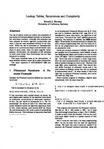
2. Dynamic Circuit Specialization Dynamic Circuit Specialization (DCS) enables us to implement a parameterized application with less FPGA resources (mainly Lookup Tables) compared to the classic static FPGA implementation. An average reduction of 42% in FPGA resources is observed for an 8-bit, 16-tap adaptive Finite Impulse Response (FIR) filter application. This also helps in shortening the critical path of the design and thus it improves the filter’s performance [2]. The tool flow that implements DCS consists of two stages: a generic stage and a specialization stage. In the generic stage, a parameterized application (or design) described in a Hardware Description Language (HDL) is processed to yield a Partial Parameterized Configuration (PPC) and a Template Configuration (TC) as depicted in Figure 1. The PPC contains bitstreams expressed as Boolean functions
International Journal of Reconfigurable Computing of input parameters of a parameterized design. The TC contains static bits (ones and zeros) and is used for the nonreconfigurable parts of the problem. Members of our research group have found an automatic method to map a parameterized design onto virtual Lookup Tables (LUTs) called Tunable Lookup Tables (TLUTs) [2]. TLUTs are the intermediate representation of physical LUTs with truth table entries (a part of the bitstreams) that are expressed as Boolean functions of the parameters instead of regular bitstreams. (A TLUT is a virtual version of a physical LUT whose features are identical to the physical LUT of an FPGA, except that the truth table entries are dependent on the parameters.) Therefore, during the reconfiguration, only the truth table entries of the TLUTs are replaced with the specialized bits that are generated during the specialization stage. In the specialization stage, the Boolean functions are evaluated for specific values of the parameters thus generating specialized bitstreams. For every infrequent change in parameter values, the Boolean functions are evaluated by a specialized configuration generator (SCG). The SCG can be implemented on an embedded processor such as the PowerPC or the ARM Cortex-A9 present within the FPGA core. The SCG reconfigures the FPGA via a configuration interface called the Internal Configuration Access Port (ICAP) by swapping the specialized bitstreams into the FPGA configuration memory. The configuration controller such as HWICAP (in conventional DCS implementation, the HWICAP is used as a reconfiguration controller) encapsulates the ICAP primitive (port) of the FPGA and forms a controller that orchestrates the swapping of specialized bitstreams via the interface port ICAP. The bitstreams are accessed in the form of frames and a frame is defined as the smallest addressable element of FPGA configuration data. Each frame contains reconfiguration bits of tens of LUTs and has its unique frame address that can be used to point to the frame during the reconfiguration. The software to implement DCS is available as an open source project on GitHub [7]. 2.1. DCS on the Xilinx FPGAs. The conventional implementation of DCS on the Xilinx FPGAs, such as the ZynqSoC, is shown in Figure 2. The SCG is realized on an embedded processor (ARM Cortex-A9 dual core processor or a MicroBlaze soft core processor). The PPC Boolean functions are stored in the memory such as DRAM memory of the Zynq-SoC. The ICAP is used as a configuration interface. The HWICAP reconfiguration controller is responsible for orchestrating the replacement of the stale frames with specialized frames present in the configuration memory of the FPGA. 2.2. The HWICAP Driver “XhwIcap setClb bits” Function. The HWICAP supports a software driver function called “XhwIcap setClb bits” to perform the reconfiguration. This function accepts two crucial function arguments: (1) Location coordinates of a TLUT: this information is used to generate the frame address that is used to point to the frame that contains truth table entries of the TLUT.
3 Parameter values
PPC memory
CLB Specialized configuration generator (SCG)
Configuration interface
Figure 2: Dynamic Circuit Specialization on Xilinx FPGAs.
(2) Truth table entries: these are the specialized bits generated after the specialization stage of the DCS tool flow. The TLUT truth table entries need to be overwritten with these specialized bits. The reconfiguration takes place in 3 steps: (1) Read frames: using the frame address, a set of four consecutive frames containing the truth table entries of a TLUT are read from the configuration memory. (2) Modify frames: the current truth table entries of a TLUT are replaced by the specialized bits. The modified frames contain specialized bitstreams. (3) Write-back frames: using the same frame address, the modified four frames are written back to the configuration memory, thus accomplishing the microreconfiguration. Micro-reconfiguration is a fine grain form of reconfiguration used for DCS [8]. Therefore, a reconfiguration controller in this case should be capable of reading, modifying, and writing the frames from the configuration memory and a processor should take care of executing the cycle of read, modify, and write-back frames. The micro-reconfiguration incurs 4 major costs. These costs are major drawbacks of DCS: (1) PPC Memory Size. Memory space required to store all the Boolean functions of the parameterized application.
4
International Journal of Reconfigurable Computing
In order to exploit reconfiguration in modern FPGA architectures, we have to adjust to the specific reconfiguration infrastructure in current column based FPGA architectures from Xilinx for our experiments. Since the custom reconfigurations controllers are designed to be specific to the Zynq-SoC architecture, we conduct our experiments on the Zynq-SoC FPGA only. However, the idea of improving the reconfiguration speed using custom drivers along with placement constraints can be applied to any column based Xilinx FPGA. The Xilinx FPGA on the Zynq-SoC contains an array of Configurable Logic Blocks (CLBs) which encapsulate LUTs, flip-flops, and multiplexers. Each CLB contains 8 LUTs and is capable of realizing combinational and sequential logic. The array of CLBs is divided into a number of clock regions. Each clock region contains CLB columns with a fixed number of CLBs and the height of the CLB column remains the same in all the clock regions. There are multiple CLB columns adjacent to each other thus forming CLB rows as shown in Figure 3. There are other columns such as DSP and BRAM columns that exist in between CLB columns. 3.1. Frame Structure. A frame of an FPGA is the smallest addressable element of an FPGA configuration. It can be viewed as a vertical stack of a fixed number of bits spanning a complete height of a row [9]. A fixed data size of 2 words (1 word = 32 bits) is assigned to each CLB within the entire frame. This means a set of LUT entries present in one CLB can be configured within those 2 words. However, the complete configuration data of an entire CLB containing multiple LUTs spans over four frames and each frame has its own unique frame address [9]. It should be noted that there exists one extra word called “HCLK config word” for each column within one frame as shown in Figure 4. A single frame can contain truth table entries of multiple LUTs which are located in a single CLB column. In the Zynq-7000 family, there are 50 CLBs in one column, so a total of 50 × 2 + 1 = 101 words exist in one frame. The frame size plays an important role during the reconfiguration
Clock region X0Y2
Clock region X1Y2
Clock region X0Y1
Clock region X1Y1
BRAM column DSP column
3. Column Based Xilinx FPGA Architecture
CLB column
The reconfiguration time is a major overhead of the DCS approach [8]. Using the HWICAP, the time taken to reconfigure one TLUT is 230 𝜇s. Custom reconfiguration controllers such as the MiCAP and the MiCAP-Pro offer much higher reconfiguration speeds compared to the HWICAP at the extra cost of FPGA resources.
ARM Cortex-A9 dual core processor
(2) Evaluation Time. Time taken by the SCG to evaluate the Boolean function for a specific set of parameter values. (3) Reconfiguration Time. Time taken to update all the TLUTs of a parameterized design with the specialized bits; in other words, time taken to accomplish the micro-reconfiguration. (4) Power Consumption. The idle and dynamic power consumed by the reconfiguration infrastructure during the micro-reconfiguration.
Clock region X0Y0
Clock region X1Y0
Figure 3: Column based FPGA architecture: Zynq-SoC.
process. Since a frame is the smallest addressable element, for every reconfiguration process, at least one frame has to be accessed via the HWICAP. Thus the time taken to reconfigure a LUT is affected by the frame size. For a fixed HWICAP throughput, an increase in frame size results in an increase in reconfiguration time and thus reduces the reconfiguration speed.
4. Reconfiguration Controllers The configuration data of an FPGA can be internally accessed frame by frame by an embedded processor such as the ARM Cortex-A9 (dual core) present in the Zynq-SoC. The processor can access the frames via an internal configuration interface called ICAP. The ICAP is a hardware macro or a primitive that needs a hardware driver (controller) to write or read the configuration data from the configuration memory. The maximum data throughput the ICAP supports is 400 MBps [10]. The processor has to send a series of commands to the ICAP in order to access the bitstreams from the configuration memory. There are different sets of commands to read and write the frames into the configuration memory. The
International Journal of Reconfigurable Computing 31
Word 1
0
31
Word 2
0
31
Word 3
0
31
Word 4
0
.. .
5 PS
CLB 1 MGP0
HP0 CLB 2
.. .
MiCAP-Pro DMA controller
PL GPIO ICAP
Figure 5: MiCAP-Pro architecture on the Zynq-SoC. 31
Word 49
0
31
Word 50
0
31
Word 51
0
31
Word 52
0
31
Word 53
0
CLB 24 HCLK config word CLB 25
.. .
.. .
31
Word 98
0
31
Word 99
0
31
Word 100
0
31
Word 101
0
CLB 49
CLB 50
Frame structure of Zynq-SoC (Artix-7)
Figure 4: Frame structure of a column based Xilinx Zynq-SoC.
reconfiguration controller receives these commands from the processor, channelizes them to the ICAP, and orchestrates the bitstream transactions between the processor and the configuration memory. 4.1. Hardware ICAP (HWICAP). The HWICAP is an IP provided by Xilinx. The controller is mainly intended for the partial reconfiguration and therefore contains a complex state machine with a tiny FIFO buffer. The buffer is used to temporarily store the frames before they are sent to or received from the configuration memory. The HWICAP can support a maximum clock frequency of 100 MHz. The maximum data throughput of the HWICAP is 19 MBps [10]. The “XhwIcap setClb bits” is a HWICAP software driver that is responsible for reconfiguring a LUT given its location coordinates and the truth table entries. Therefore, this driver is used for the implementation of DCS. 4.2. MiCAP. The Micro-Reconfigurable Configuration Access Port (MiCAP) is a custom reconfiguration controller used to micro-reconfigure the frames of a parameterized design [6]. The controller has a simple state machine and an individual input and output buffer. The depth of the buffers is sufficient to hold all the required data including ICAP
commands and the bitstreams. We have shown that MiCAP improves the reconfiguration speed by 17% and consumes 50% less resources than the HWICAP. However, the MiCAP suffers from a major bottleneck while transferring the data between PL and PS regions of the Zynq-SoC. The MiCAP software driver function “MiCAP setClbbits” uses the same principle (read-modify-write-back frames) of the “XhwIcap setClb bits” function. The function reconfigures only a single TLUT for every function call. 4.3. MiCAP-Pro. The pro. version of the MiCAP overcomes the data transfer bottleneck between the Processor System (PS) region and the Programmable Logic (PL) region of the Zynq-SoC. The data transfer between the ICAP and the processor occurs via High Performance (HP) ports of the SoC. It uses a DMA controller for a high speed data transaction. The reconfiguration speed is improved by a factor ≈3. However, the improvement of reconfiguration speed comes at the cost of the FPGA resource that is ≈3 times higher than the HWICAP. The block diagram of the MiCAP-Pro is shown in Figure 5. The MiCAP-Pro uses the same driver “MiCAP setClbbits” that includes minor changes to use DMA related functions to transfer the data via HP ports of the Zynq-SoC. The MiCAP-Pro is a more advanced controller than other reconfiguration controllers such as the ZyCAP [10] and the FaRM [11]. The ZyCAP does not support configuration readback and the FaRM supports configuration read-back but the controller can be implemented only on the PLB bus. The MiCAP-Pro is capable of reading and writing the configuration frames compatible with the AXI bus.
5. Custom Reconfiguration Drivers In this section, we propose two different principles to modify the reconfiguration drivers of the corresponding reconfiguration controllers. These modifications optimize the read activity during the micro-reconfiguration. 5.1. Type 1: Mutliread, Multimodify, and Multiwrite. The conventional drivers follow the read-modify-write-back principle to reconfigure every TLUT separately. In order to exploit the advantage of the existing frame structure that is imposed by the column based Xilinx FPGA architecture, we propose to modify truth table entries of multiple TLUTs within a single read activity. If multiple TLUTs of a parameterized design are
6
International Journal of Reconfigurable Computing
placed in a single column then each of these TLUTs has a certain set of truth table entries that are located in the same frame. However, all 64 entries of a single TLUT are spread over 4 different frames. We have modified the reconfiguration process (into driver type 1) that takes place in 3 steps: (1) Read multiple frames: with the help of the frame address, four frames containing all the truth table entries of a column of TLUTs and LUTs are read from the configuration memory. If there are multiple TLUTs placed in a single column, the truth table values of multiple TLUTs are read with a single read activity. (2) Modify frames: before modification, the function locates the truth table bits of all the TLUTs that are present in the frame. The current truth table entries of these TLUTs are replaced with the specialized truth table bits, which are generated by the SCG. Thus multiple TLUTs are specialized in a single attempt. (3) Write-back frames: with the help of the same frame address, the modified or specialized truth table values are updated in all the TLUTs of the column by swapping in multiple frames into the configuration memory of the FPGA. This updates all the truth table entries of multiple TLUTs that are placed in a single column. Hence for a single read frames activity, multiple TLUTs can be reconfigured and this proves to be efficient since reading and writing back the frames for each TLUT can be avoided in contrast to the case of the conventional driver. If the number of TLUTs in a parameterized design is higher than what fits in a single CLB column then multiple CLB columns containing multiple TLUTs can be used in order to achieve the gain in reconfiguration speed. The TLUTs can be forcibly placed in a single column by using design placement constraints. However, the main concern with using the placement constraints is the design performance. Strict placement constraints would lead to hindrance of the design performance. There will be a tradeoff between the reconfiguration speed and the design performance which is investigated in Section 7. 5.2. Type 2: Read Once, Multimodify, and Multiwrite. The type 1 reconfiguration driver can be further optimized at the cost of DRAM memory. The memory is used as a cache to store the frames that are read during a reconfiguration. We have optimized the read frame activity for future reconfiguration of the same TLUTs. (1) Read Frames Once. With the help of the frame address, four frames containing all the truth table entries of a column of TLUTs and LUTs are read from the configuration memory. If there are multiple TLUTs placed in a single column, the truth table values of multiple TLUTs are read with a single read activity. Once the frames are read, each frame is stored in DRAM memory of the Zynq-SoC. If the processor has to reconfigure the same TLUTs at a later time, it can directly access the frames from the DRAM memory instead of
Table 1: Dimensions for the placement constraints. Number of TLUTs to be clustered Zynq-SoC
16-tap FIR
32-tap FIR
64-tap FIR
384
768
1536
50 × 5
50 × 11
50 × 14
Note: the above dimensions are in the form of length × width of the CLB columns. Each column contains 200 LUTs.
requesting the same frames from the configuration memory via the ICAP. Since the data access from the DRAM memory is faster than the configuration memory, the read frame activity can be bypassed for the future reconfigurations of the same TLUTs. The rest of the reconfiguration steps: multimodify and multi-write-back frames remain unchanged. However, the bitstream’s cache is updated for every write-back activity in order to keep the cached bitstream consistent with the actual configuration of the FPGA.
6. Placement Constraints The main aim of using placement constraints in our setting is to force multiple TLUTs to cluster all their truth table entries in a minimal number of frames. The placement constraints are used to restrict where the design’s logic is placed. It forces the placer to use a certain area of the FPGA. We have described the correlation between the CLB columns and the frame structure in Section 3. Our approach is to force more TLUTs to be placed in a single CLB column so that their truth table entries can be reconfigured with a minimal access of configuration frames. We have used the “AREA GROUP” constraint [12]. This constraint allows us to specify that certain parts of the design can only be placed in a predetermined rectangular region of the FPGA’s CLBs. To determine the exact size of this rectangular region the maximum length of the CLB column and minimum width of the CLB rows have to be considered. The maximum length of the CLB column is equal to its height (50 for the Zynq-SoC) in a given clock region and it ensures that more TLUTs can fit the specified area, while the minimum CLB rows ensure that we use the minimal number of CLB columns possible. We first used the constraint to place the TLUTs in an exact minimum number of CLB columns determined by the number of LUTs present in it. For example, in the ZynqSoC each column has 200 LUTs. Therefore to place the 64tap FIR filter (1536 TLUTs), it is sufficient to use 8 columns. However with 8 columns, the router was not able to route the design. Hence we increased the width of the rectangular area by increasing the number of columns until the router was able to route the whole design. The width of the rectangular area in terms of CLB columns for different configurations of the FIR filter is tabulated in Table 1. For a 64-tap FIR filter, the average number of TLUTs clustered in a single CLB column of the Zynq-SoC is 110 which is 52% of the total LUTs available in a single CLB column and there are a maximum of 156 TLUTs clustered in a single
International Journal of Reconfigurable Computing
7
Table 2: TLUTs cluster rate of a 64-tap FIR filter in a single CLB column.
Input x[n]
Zynq-SoC Average 52% 48%
Clustered TLUTs Unclustered TLUTs
Maximum 75% 25%
Table 3: FIR filter configurations. Taps 16 32 64
Multipliers 32 64 128
C1
· · · Ck−1
C2 +
TLUTs 384 768 1536
+
Figure 6: 𝑘-tap, 8-bit FIR filter.
column which is 75%. The remaining LUTs are not a part of the reconfiguration process and hence they are used for the nonreconfigurable parts of the problem. Table 2 shows the percentage of TLUTs clustered.
In order to evaluate the performance of the reconfiguration controllers after using custom reconfiguration drivers, we first set up a DCS system on a self-reconfigurable platform. In this section, we describe the experimental setup of the parameterized design implemented using DCS with different reconfiguration controllers. We implemented the controllers and used modified drivers (type 1 and type 2) on a selfreconfigurable DCS platform and measured the reconfiguration speed. 7.1. Parameterized FIR Filter. We implement an 8-bit FIR filter with three different tap configurations as a parameterized design. Each filter tap contains two 4-bit multipliers and each multiplier is mapped onto 12 TLUTs [3]. We use the FIR filters with different configurations as listed in Table 3. Figure 6 shows the structure of the filter. All coefficients form the parameterized inputs and for every change in the coefficient value, a specialized bitstream is generated and the filter taps containing multiplications are reconfigured accordingly. 7.2. Self-Reconfigurable Platform. We have used a selfreconfigurable platform [3] for implementing a parameterized FIR filter using DCS. Three different reconfiguration controllers (HWICAP, MiCAP, and MiCAP-Pro, each clocked at 100 MHz) were used for individual experiments. The platform is depicted in Figure 7. We used a Zynq-SoC (XC7Z020-CLG484-1, ZedBoard) FPGA and Xilinx XPS v14.7 for the project system builder. The PPC Boolean functions are stored in the DRAM memory of the Processor System (PS) and all the actions of the micro-reconfiguration are controlled by the ARM Cortex-A9 processor (clocked at 667 MHz). Therefore, the user can use a simple program to run software on the processor to control and measure the reconfiguration activity. The whole system
+ Output y[n]
ARM Cortex-A9
7. Experimental Setup
Ck
DRAM
AXI
Reconfiguration controller
Parameterized FIR filter
Figure 7: A self-reconfigurable platform for DCS implementation.
is connected using the AXI bus (clocked at 100 MHz) for the data transfer. 7.3. Reconfiguration Speed Measurement. We measured the reconfiguration speed of a single TLUT of a parameterized design using soft-timers. We also evaluated the total time to reconfigure all the TLUTs of the parameterized design (total reconfiguration time). First the experiments were conducted without placement constraints. The experiments were performed using both types of reconfiguration software drivers (type 1 and type 2) on individual reconfiguration controllers separately. Further, the experiments were conducted by constraining the TLUTs to cluster their truth table entries in the same frames by using placement constraints. Using placement constraints results in a reduction of the design’s performance. Therefore, we have measured the maximum clock frequency the design can support for the experiments using placement constraints and without placement constraints.
8. Results and Discussion In this section, we present the results of our experiments. Table 4 shows the reconfiguration time distribution of a TLUT using three different reconfiguration controllers. Clearly, MiCAP-Pro is the fastest reconfiguration controller between all three controllers. In order to evaluate the effect of using custom reconfiguration drivers on the three controllers, we consider the total reconfiguration time (time taken to reconfigure all the TLUTs of the DCS system).
8
International Journal of Reconfigurable Computing Table 4: Reconfiguration time distribution of a single TLUT.
Reconfiguration controller HWICAP
MiCAP
MiCAP-Pro
Micro-reconfiguration task Read frames Boolean evaluate and modify Write-back frame Read frames Boolean evaluate and modify Write-back frames Read frames Boolean evaluate and modify Write-back frames
Table 5: CLB columns TLUTs placed without placement constraints. Number of TLUTs to be clustered CLB columns
16-tap FIR
32-tap FIR
64-tap FIR
384
768
1536
25
42
50
There were 3 different experiments conducted on each of the reconfiguration controllers: (1) Experiments with type 1 reconfiguration drivers and without placement constraints. (2) Experiments with type 1 reconfiguration drivers and with placement constraints. (3) Experiments with type 2 reconfiguration drivers and with placement constraints. 8.1. Experiments with Type 1 Reconfiguration Drivers and without Placement Constraints. In this experiment, we have not used placement constraints and hence the TLUTs were automatically placed by the placer without constraints from the user. The placer tool had full freedom to choose its own place for the TLUTs in different CLB columns. Table 5 shows the number of columns in which the TLUTs were placed by the placer without any placement constraints. Further investigations have shown that there were multiple TLUTs placed for a given CLB column and therefore, we can still use the principle of modifying multiple TLUTs for a single read activity. The TLUTs of the parameterized FIR filter design were reconfigured with 3 different reconfiguration controllers. We used custom reconfiguration drivers of type 1. The corresponding time required to reconfigure all the TLUTs of the parameterized design and the Improvement Factor (IF) is tabulated in Table 6. Clearly, there was a drastic reduction in the reconfiguration time compared to the standard reconfiguration drivers. The reconfiguration speed was improved drastically at least by a factor of 12 for the HWICAP and the MiCAP. Similarly, the improvement in reconfiguration speed by a factor of ≈8 was observed for the MiCAP-Pro. This improvement was
Time (𝜇s) 111.5 18 100.5 97 18 95 23 18 23.1
TLUT reconfiguration time (𝜇s) 234
210
64.1
achieved since we overcome the reading of the same frames that contain configuration of multiple TLUTs. The data transfers between PS and PL regions of the Zynq-SoC are the major bottleneck for the HWICAP and the MiCAP. Therefore, bypassing the frame read activities in the driver contributes a lot to the reconfiguration speed and is the major reason for the improvement in the reconfiguration speed. Since we did not use any placement constraints, the overall performance of the DCS system remains unchanged. 8.2. Experiments with Type 1 Reconfiguration Drivers and with Placement Constraints. In this experiment, we force the placer tool to place the maximum possible number of TLUTs in an exact minimum number of CLB columns by using “AREA GROUP” placement constraints. Table 1 shows the minimum CLB columns in which the TLUTs were placed. The parameterized design was reconfigured using type 1 drivers using three different controllers. The total reconfiguration time is tabulated in Table 7. Clearly, the reconfiguration speed was even further improved by at least a factor ≈20 for the HWICAP and MiCAP. The reconfiguration speed was improved at least by a factor ≈8 for the MiCAP-Pro. The improvement is due to the placement of TLUTs in a reduced number of CLB columns compared to the previous experiment. With the help of the placement constraints, the truth table entries of multiple TLUTs were clustered in a single CLB column. Therefore, this method gives an advantage of modifying more TLUTs for a single frame read activity. The type 1 driver exploits the advantage and reconfigures multiple TLUTs thereby reducing the reconfiguration time. The improvement in the reconfiguration speed comes at the cost of a reduction in the design performance. Introducing the placement constraints causes the design to have a longer critical path than the conventional implementation. This causes a decrease in the maximum clock frequency the design can support as observed in Table 8. Clearly, an increase in the number of TLUTs decreases the design performance. The overall average deterioration in design performance is about 6 MHz (or a deterioration of ≈6%). 8.3. Experiments with Type 2 Reconfiguration Drivers and with Placement Constraints. In this experiment, we used a custom
International Journal of Reconfigurable Computing
9
Table 6: Total reconfiguration time without placement constraints. FIR filter taps
TLUTs
16
384
32
768
64
1536
Reconfiguration controller HWICAP MiCAP MiCAP-Pro HWICAP MiCAP MiCAP-Pro HWICAP MiCAP MiCAP-Pro
Total reconfiguration time (ms) 88.3/7.4 80.6/6.9 24.6/3.3 176.6/13.1 161.2/12.2 49.2/6.2 353.2/18.4 322.4/17.4 98.4/12.1
IF 12 12 8 13 13 8 19 19 8
Note 1: the above timing values are in the form of normal reconf. drivers/custom type 1 reconf. drivers. Note 2: IF stands for Improvement Factor.
Table 7: Total reconfiguration time with placement constraints. FIR filter taps
TLUTs
16
384
32
768
64
1536
Reconfiguration controller HWICAP MiCAP MiCAP-Pro HWICAP MiCAP MiCAP-Pro HWICAP MiCAP MiCAP-Pro
Total reconfiguration time (ms) 88.3/4.4 80.6/4.3 24.6/3.1 176.6/9 161.2/8.7 49.2/6 353.2/16.4 322.4/16.1 98.4/9.6
IF 20 19 8 20 19 8 22 20 10
Note 1: the above timing values are in the form of normal reconf. drivers/custom type 1 reconf. drivers. Note 2: IF stands for Improvement Factor.
Table 8: Maximum clock the design can support on the Zynq-SoC.
Number of TLUTs to be clustered Clock frequency in MHz
16-tap FIR
32-tap FIR
64-tap FIR
384
768
1536
108.6/102.8
108.6/102.2
108.6/101.2
Note: the above values are in the form without placement constraints/with placement constraints.
reconfiguration driver of type 2. Introducing the placement constraints reduces the number of CLB columns in which the TLUTs are placed. When using a custom driver of type 2, the frames that contain TLUT truth table entries are stored in the DRAM of the Zynq-SoC after they are read during the reconfiguration of the TLUTs for the first time. The DRAM acts as a cache so that we can reuse the truth table entries for reconfiguring the same TLUTs in future requests. Therefore, we bypass the frame read activity and hence the reconfiguration time is reduced. Table 9 shows the reconfiguration time of the DCS system after using the type 2 reconfiguration driver. Clearly, we observe an improvement in reconfiguration speed by 12% compared to the type 1 driver. However, this small improvement comes at the cost of memory that is used to store the frames for reconfiguring the TLUTs. The DRAM
should store at least 404 words (1 word = 32 bits) of the frame data to reconfigure multiple TLUTs present in a single CLB column. We limit the use of the type 2 driver to the experiments with placement constraints only. This is because the number of frames that contain truth table entries of TLUTs is small compared to the number of frames without placement constraints and therefore it is worth storing minimum possible frames rather than storing the frames that contain TLUTs which are widespread across the multiple clock regions of the FPGA. For a 64-tap parameterized FIR filter, in order to store all the frames (that contain truth table entries of 1536 TLUTs) in the DRAM memory, we need a memory space of 5656 words (14 × 404 = 5656) or ≈23 KB in the DRAM memory. The comparison of the reconfiguration time of the parametrized FIR filter with 64 taps implemented using DCS using different reconfiguration controllers is depicted in Figure 8. The naming conventions used in Figures 8–11 are described in Table 10. Clearly, the TLUTs of the parameterized design are reconfigured efficiently with less overhead of reconfiguration time using custom reconfiguration controllers when used along with custom type 1 and type 2 reconfiguration drivers. 8.4. Functional Density. The effect of variations in the reconfiguration speed and the effect of introducing the placement
10
International Journal of Reconfigurable Computing Table 9: Reconfiguration time using type 2 drivers.
FIR filter taps
TLUTs
16
384
32
768
64
1536
Reconfiguration controller HWICAP MiCAP MiCAP-Pro HWICAP MiCAP MiCAP-Pro HWICAP MiCAP MiCAP-Pro
Total reconfiguration time (ms) 4.4/3.8 4.3/3.8 3.1/2.8 9/7.7 8.7/7.7 6/5.4 16.4/14.7 16.1/14.7 9.6/9
(Reconf Controller)4
Note: (Reconf Controller) can be HWICAP, MiCAP, and MiCAP-Pro in the above naming convention.
constraints to improve the reconfiguration speed in DCS can be best explained using the functional density curve [13]. The functional density is defined as the number of computations (𝑁) that can be performed per unit area (𝐴) and unit time (𝑇) as shown in 𝑁 (1) . 𝐹𝑑 = 𝐴×𝑇 In our experiments, the computations are all the operations in the FIR filter. The value of “𝐴” depends on the resources of the FPGA used by the FIR filter (mainly TLUTs). The value of “𝑇” is the reconfiguration time, the execution time, and the time to specialize. A higher functional density signifies a more efficient usage of implementation area. The functional density curve was plotted against the rate of change of the input parameters for the parameterized design implementation. We have plotted the functional density curve for each reconfiguration controller and observed
MiCAP-Pro4
MiCAP-Pro3
MiCAP-Pro2
MiCAP-Pro1
MiCAP4
MiCAP3
MiCAP2
MiCAP1
(Reconf Controller)3
HWICAP4
(Reconf Controller)2
HWICAP3
(Reconf Controller)1
Definition DCS system with (Reconf Controller) and standard reconfiguration driver (read, single modify, and write). DCS system with (Reconf Controller), with custom type 1 reconfiguration driver and without placement constraints. DCS system with (Reconf Controller), with custom type 1 reconfiguration driver, and with placement constraints. DCS system with (Reconf Controller), with custom type 2 reconfiguration driver, and with placement constraints.
380 360 340 320 300 280 260 240 220 200 180 160 140 120 100 80 60 40 20 0
HWICAP2
Reconfiguration controllers
Reconfiguration time (ms)
Table 10: Naming convention for reconfiguration controllers.
HWICAP1
Note: the above values are in the form of custom type 1 drivers/type 2 drivers.
Reconfiguration controllers
Figure 8: Reconfiguration time comparison between standard reconfiguration driver and custom reconfiguration drivers.
the variation in functional density of the DCS system after using standard, custom type 1 without placement constraints and type 1 and custom type 2 drivers with placement constraints. The functional density curves for the HWICAP, the MiCAP, and the MiCAP-Pro are depicted in Figures 9, 10, and 11, respectively. The naming conventions for the reconfiguration controllers are listed in Table 10. The 𝑥-axis represents the average time (in clock cycles) between two parameter value changes. We observe a similar behavior of functional density curves in the DCS systems implemented using three different reconfiguration controllers. The functional density for the DCS with custom type 1 driver (without placement constraints) rises well before the functional density of the DCS that uses the standard reconfiguration driver, introducing the placement constraints for type 1 and type 2 custom drivers improves the reconfiguration speed furthermore, and hence the corresponding functional density curves rise earlier compared to the functional density curve with standard reconfiguration drivers. This shows that improving the reconfiguration speed allows the parameters to change faster with the same gain in area compared to
International Journal of Reconfigurable Computing
11
Functional density ((Ops/s)/LUT)
Functional density ((Ops/s)/LUT)
×105 8 6 4 2 0 104
105
106 107 108 109 Parameter reuse (clock cycles)
HWICAP1 HWICAP2
1010
1011
HWICAP3 HWICAP4
Functional density ((Ops/s)/LUT)
×105 10 8 6 4 2 105 MiCAP1 MiCAP2
106 107 108 109 Parameter reuse (clock cycles)
6 5 4 3 2 1 0 104
105
106 107 108 Parameter reuse (clock cycles)
MiCAP-Pro1 MiCAP-Pro2
Figure 9: Functional density curves for HWICAP with different reconfiguration drivers.
0 104
×105 7
1010
1011
MiCAP3 MiCAP4
Figure 10: Functional density curves for MiCAP with different reconfiguration drivers.
DCS whose reconfiguration speed is slow. However, since the design performance is slightly reduced due to placement constraints, the magnitude of the functional density curves is relatively lower compared to the DCS without placement constraints forming the main trade-off. The HWICAP and the MiCAP have similar functional density curves (except the MiCAP has a higher magnitude of functional density) since they have approximately equal throughput [6]. Using the custom reconfiguration drivers improves the reconfiguration speed drastically. However, the functional density curves for the MiCAPPro only show a small improvement in reconfiguration speed after using type 1 and type 2 reconfiguration drivers. Since the data throughput of the MiCAP-Pro is very high, the effect of using custom reconfiguration drivers to improve the reconfiguration speed is relatively lower. The impact of using placement constraints can be also seen in the functional density curves of the MiCAP-Pro.
109
1010
MiCAP-Pro3 MiCAP-Pro4
Figure 11: Functional density curves for MiCAP-Pro with different reconfiguration drivers.
Commercial applications such as Ternary Content Addressable Memories (TCAMs) used for packet classification in network routers [14] can benefit from DCS. An entry (content) of the memory is an infrequently changing input value and, therefore, can be used as a parameter input. However, in the network routing if the content of the TCAM has to be updated then the reconfiguration speed plays an important role. If the reconfiguration speed is too slow then it affects the network router’s performance. The parameterized TCAMs can benefit from our proposed methods and overcome the barrier of the reconfiguration time without affecting the router’s performance.
9. Conclusion In order to efficiently reconfigure the TLUTs of a DCS system with less reconfiguration time overhead, we have proposed two different custom reconfiguration software drivers: type 1 and type 2. The reconfiguration time can be further suppressed using design placement constraints. We constrained the TLUTs of the FIR filter within the minimal number of columns possible. The custom reconfiguration drivers of type 1 were optimized to read and write the frames only once to reconfigure multiple TLUT entries. Further, in custom type 2 drivers, the frames that are read (during microreconfiguration) are stored in DRAM memory. These stored frames are used by the processor to modify the TLUTs in the future reconfiguration of the same TLUTs, thus saving the time to read the same frames for the future reconfiguration requests. The concept of optimization (type 1 and type 2) was applied to the reconfiguration drivers of the custom reconfiguration controllers MiCAP and MiCAP-Pro. Improvements in the reconfiguration speed were observed. We have shown that there is a drastic improvement in the reconfiguration speed but this comes at the cost of a slight reduction in performance of the design (due to placement constraints). The functional density curves were used to analyze the impact
12 of using high speed reconfiguration controllers in the DCS system. The custom reconfiguration controllers MiCAP and MiCAP-Pro can be accessed at [15] and [16], respectively. The custom reconfiguration drivers type 1 and type 2 can be accessed at [17] and [18], respectively.
Competing Interests The authors declare that they have no competing interests.
Acknowledgments This work was supported by the European Commission in the context of the H2020-FETHPC EXTRA project (no. 671653). The authors would like to thank Dr. Karel Heyse, Dr. Tom Davidson, Dr. Vipin Kizheppatt, and Dr. Robin Bonamy for their timely advice and valuable suggestions.
References [1] P. Lysaght, B. Blodget, J. Mason, J. Young, and B. Bridgford, “Invited paper: enhanced architectures, design methodologies and CAD tools for dynamic reconfiguration of Xilinx FPGAS,” in Proceedings of the International Conference on Field Programmable Logic and Applications (FPL ’06), pp. 1–6, Madrid, Spain, August 2006. [2] K. Bruneel, W. Heirman, and D. Stroobandt, “Dynamic data folding with parameterizable FPGA configurations,” ACM Transactions on Design Automation of Electronic Systems, vol. 16, no. 4, pp. 1–29, 2011. [3] K. Bruneel, F. Abouelella, and D. Stroobandt, “Automatically mapping applications to a self-reconfiguring platform,” in Proceedings of the Design, Automation and Test in Europe Conference and Exhibition (DATE ’09), pp. 964–969, Leuven, Belgium, April 2009. [4] K. Papadimitriou, A. Dollas, and S. Hauck, “Performance of Partial Reconfiguration in FPGA systems: a survey and a cost model,” ACM Transactions on Reconfigurable Technology and Systems, vol. 4, pp. 1–24, 2011. [5] A. Kulkarni, T. Davidson, K. Heyse, and D. Stroobandt, “Improving reconfiguration speed for dynamic circuit specialization using placement constraints,” in Proceedings of the International Conference on ReConFigurable Computing and FPGAs (ReConFig ’14), pp. 1–6, Cancun, Mexico, December 2014. [6] A. Kulkarni, V. Kizheppatt, and D. Stroobandt, “MiCAP: a custom reconfiguration controller for dynamic circuit specialization,” in Proceedings of the International Conference on ReConFigurable Computing and FPGAs (ReConFig ’15), pp. 1–6, IEEE, Cancun, Mexico, December 2015. [7] TLUT Tool Flow Based Dynamic Circuit Specialization, 2013, https://github.com/UGent-HES/tlut flow. [8] A. Kulkarni, K. Heyse, T. Davidson, and D. Stroobandt, “Performance evaluation of dynamic circuit specialization on Xilinx FPGAs,” in Proceedings of the FPGA World Conference, Stockholm, Sweden, September 2014. [9] 7 Series FPGAs Configuration: User Guide, UG470 (v1.10), Xilinx Inc, 2015.
International Journal of Reconfigurable Computing [10] K. Vipin and S. A. Fahmy, “ZyCAP: efficient partial reconfiguration management on the xilinx zynq,” IEEE Embedded Systems Letters, vol. 6, no. 3, pp. 41–44, 2014. [11] F. Duhem, F. Muller, and P. Lorenzini, “Reconfiguration time overhead on field programmable gate arrays: reduction and cost model,” IET Computers and Digital Techniques, vol. 6, no. 2, pp. 105–113, 2012. [12] Xilinx, Constriants Guide (cgd 10.1), Xilinx, San Jose, Calif, USA, 2015. [13] A. DeHon, Reconfigurable Architectures for General-Purpose Computing, Massachusetts Institute of Technology Artificial Intelligence Laboratory, 1996. [14] K. Pagiamtzis and A. Sheikholeslami, “Content-Addressable Memory (CAM) circuits and architectures: a tutorial and survey,” IEEE Journal of Solid-State Circuits, vol. 41, no. 3, pp. 712–727, 2006. [15] MiCAP: A custom Reconfiguration Controller for Dynamic Circuit Specialization, 2015, https://github.com/UGent-HES/ MiCAP. [16] MiCAP-Pro: A High Speed Custom Reconfiguration Controller for Dynamic Circuit Specialization, 2015, https://github.com/ UGent-HES/MiCAP-Pro. [17] Custom Reconfiguration Drivers for DCS (Type 1), 2015, https://github.com/UGent-HES/Custom-Reconfiguration-Drivers-for-DCS-Type-1. [18] Custom Reconfiguration Drivers for DCS (Type 2), 2015, https://github.com/UGent-HES/Custom-Reconfiguration-Drivers-for-DCS-Type-2.
International Journal of
Rotating Machinery
Engineering Journal of
Hindawi Publishing Corporation http://www.hindawi.com
Volume 2014
The Scientific World Journal Hindawi Publishing Corporation http://www.hindawi.com
Volume 2014
International Journal of
Distributed Sensor Networks
Journal of
Sensors Hindawi Publishing Corporation http://www.hindawi.com
Volume 2014
Hindawi Publishing Corporation http://www.hindawi.com
Volume 2014
Hindawi Publishing Corporation http://www.hindawi.com
Volume 2014
Journal of
Control Science and Engineering
Advances in
Civil Engineering Hindawi Publishing Corporation http://www.hindawi.com
Hindawi Publishing Corporation http://www.hindawi.com
Volume 2014
Volume 2014
Submit your manuscripts at http://www.hindawi.com Journal of
Journal of
Electrical and Computer Engineering
Robotics Hindawi Publishing Corporation http://www.hindawi.com
Hindawi Publishing Corporation http://www.hindawi.com
Volume 2014
Volume 2014
VLSI Design Advances in OptoElectronics
International Journal of
Navigation and Observation Hindawi Publishing Corporation http://www.hindawi.com
Volume 2014
Hindawi Publishing Corporation http://www.hindawi.com
Hindawi Publishing Corporation http://www.hindawi.com
Chemical Engineering Hindawi Publishing Corporation http://www.hindawi.com
Volume 2014
Volume 2014
Active and Passive Electronic Components
Antennas and Propagation Hindawi Publishing Corporation http://www.hindawi.com
Aerospace Engineering
Hindawi Publishing Corporation http://www.hindawi.com
Volume 2014
Hindawi Publishing Corporation http://www.hindawi.com
Volume 2014
Volume 2014
International Journal of
International Journal of
International Journal of
Modelling & Simulation in Engineering
Volume 2014
Hindawi Publishing Corporation http://www.hindawi.com
Volume 2014
Shock and Vibration Hindawi Publishing Corporation http://www.hindawi.com
Volume 2014
Advances in
Acoustics and Vibration Hindawi Publishing Corporation http://www.hindawi.com
Volume 2014