Hyper-acceleration and HW/SW co-verification as an essential part of IBM eServer z900 verification Hardware/software (HW/SW) co-verification can considerably shorten the time required for system integration and bring-up. But coverification is limited by the simulation speed achievable whenever hardware models are required to verify hardware and software interactions. Although the use of a generalpurpose hardware accelerator as an extremely fast simulator resolves performance aspects, it generates a new set of handling, efficiency, and serviceability demands. This paper describes a means for addressing those demands through the use of one of the largest hyper-acceleration systems created thus far, and describes many new associated features that have been implemented in operating software.
Introduction The development process of a high-end server system typically consists of multiple phases, including design, implementation, simulation, physical design, and finally,
by J. Kayser S. Koerner K.-D. Schubert
as soon as the first functional chips are available, system bring-up and testing. A very important milestone in this sequence is power-on (PON), the state in which the first chips have been manufactured and bring-up can begin. To reduce the overall time to market, it is very important to reduce the bring-up-and-test time after PON by increasing overall system quality through extended simulation. The system generally consists of a set of chips and associated firmware, which is a software layer that is invisible to the customer but is required in order to deliver the more complex functions of the architecture on top of the hardware. The overall quality of the system is generally a combination of hardware quality, software quality, and the success with which the parts interact. Various methods such as model checking or directed random test-case generation are used to ensure that the hardware is functioning properly. By applying these methods first to units, then to single chips, and finally to multiple chips, almost all hardware problems can be found prior to “tape-out” by using standard simulation techniques. The majority of the code is typically verified without the target hardware [1] by using behavioral
娀Copyright 2002 by International Business Machines Corporation. Copying in printed form for private use is permitted without payment of royalty provided that (1) each reproduction is done without alteration and (2) the Journal reference and IBM copyright notice are included on the first page. The title and abstract, but no other portions, of this paper may be copied or distributed royalty free without further permission by computer-based and other information-service systems. Permission to republish any other portion of this paper must be obtained from the Editor. 0018-8646/02/$5.00 © 2002 IBM
IBM J. RES. & DEV.
VOL. 46 NO. 4/5 JULY/SEPTEMBER 2002
J. KAYSER ET AL.
597
models. This is sufficient as long as the code does not access special-purpose hardware features, which are usually not added to the behavioral models because of their complexity. While behavioral models are suitable for verifying most of the firmware, there remains a relatively small code layer that interacts closely with the target hardware. For the IBM eServer z900, this is mainly the firmware code used to initialize the machine (initial machine load code, or IML code). Any improvement in the simulation of these hardware/software (HW/SW) interactions before receiving the first hardware can significantly reduce the time to market. To simulate this interaction, we faced the challenge of supplying a very large simulation model of the system which can be run at a speed that allows effective code debugging. This paper presents our solution to the problem of verifying hardware-model-specific code by implementing HW/SW co-verification using a simulation system as a “hyper-accelerator” [2]. The term is used to distinguish simulation at emulation speeds (100 000 cycles per second) from typical simulation acceleration, which usually runs two to three orders of magnitude slower (1000 cycles per second).
Reasons for hyper-acceleration
598
Traditional hardware and software verification processes occur independently of one another; the major reason for this is simulation performance. Whenever a very large hardware simulation model comprising multiple chips is executed on an event- or cycle-based software simulator, the effective performance is usually in the range of a few simulation cycles per second. This is insufficient by far to do any meaningful firmware debugging. As an alternative, verification of those functions requiring interaction with the hardware is often done using behavioral models of the hardware instead of actual simulation models of the real design. Because these models are only an abstract description of the hardware, they are smaller in size and thus able to execute much faster than a real hardware model. Using behavioral models, the software simulation can achieve the reasonable performance level needed for code verification. However, because only selected portions of the design are modeled, behaviorals do not completely mimic the way real hardware will react. Since z900 IML code requires the models to respond exactly like real hardware, behavioral models cannot be used to completely verify the system initialization sequence. Thus, a significant amount of unverified IML code will escape through the software verification process and can be debugged only when a real system is powered on for the first time. To alleviate this problem, a solution was needed to model the real hardware, yet run fast enough to verify code sequences. As mentioned above, no general-purpose
J. KAYSER ET AL.
software simulator for simulating hardware is fast enough to allow a meaningful simulation of firmware on the whole model. In the industry, a general way to solve this problem is to emulate the chips under test using a hardware emulator. High performance is achieved by establishing a physical connection to the rest of the real system, where the associated software can be executed [3, 4]. For the z900, we decided to use an emulator also, but without a target system. Because the majority of chips are developed in parallel with each new system generation, there simply was no physical representation of the system available. So, in contrast to the industry, the z900 approach was to put a significant subset of our hardware system model, including multiple processor chips, cache chips, and memory, into a single hardware-emulation system and use this system as a hyper-accelerator. We do not call this emulation, because instead of physical connections to any real hardware, we have to use software to drive the model under test.
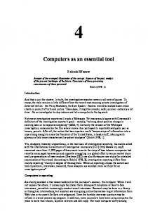
Accelerator (AWAN) and concurrent array logic 1 technology (CoBALT ) hyper-accelerator IBM has a long history of using simulation accelerators [5]. Currently within the company, use is made of the AWAN system, which is described in more detail in [6]. It is used to speed up the classical functional verification of chips. Compared with an execution speed of a few simulation cycles per second using a pure software simulator on a large model, AWAN accelerates the execution speed to several hundred simulation cycles per second. While this is significantly faster than any software simulator, the performance is still not sufficient to execute 9 the required amount of code, which is roughly 2 ⫻ 10 cycles in less than four hours. Speed of this magnitude is needed for efficient debugging of IML code. To address this problem, the construction of one of the largest hyper-acceleration systems ever created has been initiated; 1 this is the CoBALTTM system, which is installed at IBM Boeblingen. The system was developed under a partnership with the Quickturn Corporation. The z900 system contains a total of 25 million two-way NAND gate functions. The CoBALT system (Figure 1) achieved an execution speed of more than 50 000 simulation cycles per second while using a model which reflects the actual hardware implementation. It achieves this by utilizing parallel processing techniques, enabling 66 560 processors to work simultaneously to calculate the model state. The CoBALT system improves performance by a factor of 10 000 over software simulation, enabling HW/SW co-verification to occur and verify the initialization and A product of the Quickturn 娃 Corporation, a Cadence 䉸 company, San Jose, CA 95134.
1
IBM J. RES. & DEV.
VOL. 46 NO. 4/5 JULY/SEPTEMBER 2002
loading phases of the new system even before actual system integration starts. Having this innovative new system is one part of the solution. The second part, however, is to make efficient use of it. Several problems had to be solved to exploit the huge capacity and speed of the CoBALT system. The problems fell into three major categories: how to build a model of the required size, how to improve the model access methods without limiting performance, and finally, how to debug problems discovered by the system.
Model size and model build The development of the emulation model deserves particular attention. As for any hardware simulation, the design, represented in VHDL (a hardware description language) must be compiled into an executable object, the model. The compilation process is also known as the model build process. The CoBALT system has a parallel processing capability of 66 560 processors and can hold a maximum of about 15 million three-way NAND gates. 2 The quality of the scheduling software as part of the model build determines how efficiently the available gates can be used and therefore limits the maximum size of the hardware design that can be fit into the model. Today’s scheduling software can utilize between 70% and 80% of the available resources for the z900 models. Besides the size of the model, the other most important properties of the model are what pieces of the system are contained in the model, the time it takes to construct it, the time it takes to load it into the emulator, and the speed of execution once mapped into the emulator. As described earlier, the z900 program develops not just a single chip but a whole set of chips in parallel. Therefore, in-circuit emulation in the traditional sense, using target hardware to drive the machine, could not be applied. This also implies that the process relies heavily on the ability to build and schedule a large model made up of various chips, with some chips having to be duplicated multiple times in a single model. Since getting the model into the emulator was not easy because of its large size, our goal was to first optimize the process for fast and dependable model builds, then work on improving the system speed of the emulator. By adding the gate counts of the individual chips, a quick calculation showed that the largest model we could build would contain two processor chips, half of our memory subsystem (including cache chips and memory controllers), the clock controller, and one of the I/O adapter chips. This configuration was chosen because it corresponds to the minimum model configuration that is required to run unmodified IML code. 3 2
Equivalent to 25 million two-way NAND gates. A simplified model, i.e., not comprising all of the components listed above, requires that changes in the IML code be simulated. 3
IBM J. RES. & DEV.
VOL. 46 NO. 4/5 JULY/SEPTEMBER 2002
Figure 1 CoBALT system.
Packaging design
Chip design
VHDL compiler
Flattener
Scheduler Synthesis for emulator
Model
Figure 2 Model build process.
The biggest hurdle for the model build process, as shown in Figure 2, was dealing with the large number of read and write ports in some arrays. The scheduler, in particular, had difficulty with arrays containing many ports, even though the data width of each entry may have been only a few bits. Luckily, most of the ports were artifacts of using simulation versions of these array models, which had extra ports inserted to quickly reset all locations in just a few simulation cycles. To resolve this issue, the array models were reimplemented as latches
J. KAYSER ET AL.
599
Table 1
Comparison of model build parameters.
Latches Three-way gates Four-way gates Utilization* (%) Model build success rate (%) Model size (MB) Raw speed (cps) Model load time (s)
Software simulator
AWAN
CoBALT (16 boards)
CoBALT Ultra娃 (3 boards)
2.8M n/a n/a n/a 100 313 3–25 ⬃30
2.8M 12.4M 7.8M
2.8M 12.0M n/a 81 30 376 55,000 160
2.8M 14.1M 9.8M 91 100 352 606,000 111
100 333 650 ⬃500
*Board utilization includes gate and wiring utilization.
600
rather than multiport arrays in the VHDL source. Using these new macros, the first model was successfully built, even though it required almost 80% utilization of the COBALT system resources. This was a reason for concern, because there were still more design changes outstanding. In addition, the model build software was implemented in a 32-bit architecture, which limited the amount of addressable memory to 2 GB, and the first model build attempt came very close to the limit of memory consumption. To resolve the memory issue, the process was split into multiple steps to free up the memory as often as possible. While this extended the overall model build time because intermediate steps had to be saved and then loaded again, it allowed us to stay within the 32-bit memory limits. As time progressed, the designs grew in size because of fixes and late change requests. This resulted in larger models and increased utilization, but at a certain point the model build process began to fail in the scheduling phase. Scheduling is a central step and is responsible for mapping model gates into emulator hardware resources. The scheduling algorithm chooses a start condition randomly each time it runs, because the optimal solution cannot deterministically be predicted because of the nature of the algorithm. Repeating model build runs therefore yields different partitioning solutions for the exact same source model if different random seeds are used. Assuming that a model is successfully scheduled, however, a quality measurement that can be used to compare one run to another is the number of model steps required for the execution of a single cycle of that model, which corresponds directly to the raw emulation speed. Our measurements indicated that up to about 78% utilization, the probability of obtaining a successful model build was 100%. Above that utilization limit, however, the probability of obtaining a model that successfully completes the build process at all drops to zero very rapidly. While this is to some extent model-contentdependent, we were never successful in building a z900 model with a utilization higher than 83%. The final
J. KAYSER ET AL.
utilization for the model ultimately used in the verification of the z900 was 81%, which had a probability of success of around 30% (meaning that seven out of ten model build attempts could not successfully partition the design into the emulator at all). For the successful attempts, the raw emulation speed varied over a wide range. The fastest result produced a run-time speed of 55 000 cycles per second. To summarize this section, the model build results from Table 1 indicate that for the z900 HW/SW co-verification, the tools were stressed to the limit. The CoBALT Ultra system entries pertain to the next-generation CoBALT system. An increase of even 1% in the design size would have caused the process to exceed the limits of the scheduler, as well as the addressable memory capability. Future projects will therefore require not only an emulation system with a larger capacity, but also that the model build tools be rewritten as 64-bit applications.
Model access At the beginning of initial machine load (IML) for a z900 machine, all of the code resides on a laptop computer called the service element (SE), which is connected to the machine via a network and communicates finally with the clock-control chip that is part of the system model [7]. The goal of the simulation effort using the CoBALT system is to ensure that the microcode, which is one portion of the IML code, can be loaded into a simulated version of the machine. Once loaded, it must also be verified that the microcode can be executed after the SE starts the clocks. As soon as the point is reached at which hardware interaction with the microcode is negligible, a pure software-code simulator can be used to verify the remaining code, and the task of the simulation system is completed. A general problem in the construction of the environment surrounding a simulator is the connection of real hardware devices to the model inside. Typically, speed-matching techniques [3] have to be applied, often resulting in time-out scenarios in the software and
IBM J. RES. & DEV.
VOL. 46 NO. 4/5 JULY/SEPTEMBER 2002
IBM J. RES. & DEV.
VOL. 46 NO. 4/5 JULY/SEPTEMBER 2002
RS/6000
Sockets Service element
ET system DAS card Simulator API
hardware due to the 1000⫻-to-10 000⫻ speed difference between the real target system and the simulated model. Also, limitations in the number of available input and output pins of the simulation system may lead to situations in which pins must be multiplexed and traffic must be serialized. While attaching actual target hardware may model the real hardware behavior as closely as possible, this requires a real target system, and often special adapter hardware has to be designed and built. Because of this and the fact that target hardware for our model was not readily available, rather than using a target system to drive the z900 simulation environment, we developed a more flexible solution, which is shown in Figure 3. The hypervisor program, developed for earlier projects [8], was extended to communicate directly with the service element code via sockets, and with the clock chip in the simulated model via the hardware simulator application program interface (API). Using a pure software environment such as the hypervisor program to control the simulator instead of a real target system distinguishes hyper-acceleration from a simulation, which by our definition is using software connections rather than physical connections to a real target system to control the simulation environment, yet still achieve maximum simulation speed. Further analysis of the communication protocol between the service element and the model identified some bottlenecks in our hypervisor-based environment. Any kind of interaction between the simulated model and the software that requires the stoppage of clocks can cause significant performance degradation. For our IML simulation, the first bottleneck discovered was a sequence that was executed by the service element whenever the internal state of the chip had to be changed or observed. This lengthy sequence consisted of using long scan chains to shift data into and out of a selected chip. While the need to communicate with the chip is applicationdependent, the manner in which communication with the model took place warranted further study, since several options existed as to how to do it. For the CoBALT system used, arbitrary accesses to the content of the model were not possible in parallel with model execution. Each access required a hardware stop and a restart of the simulation afterward. Unfortunately, the time required to stop and restart added significant overhead to the access time. To control the overall initialization sequence, the IML code on the service element performed reads and writes of certain values to the clock control chip. Because the IML code could only access a serial interface to the hardware and the amount of support logic in the design was kept to a bare minimum, a complete shift of the scan chain was required to obtain even a few bits of data. This is because inside each chip, all of the latches in the design were connected in the scan. Depending on the number of latches, this required many clock cycles— of the order
Hardware model
Hypervisor
Figure 3 Block diagram of verification setup.
of 100 000 registers or more per chain. To make things worse, the shifting itself was not controlled directly by the software but from a control chip that was part of the model in the CoBALT system. This resulted in many read or write operations from the code to the simulated control chip, interleaved with the execution of a small number of cycles to incrementally perform the shift. The first measurements showed that the complete process of sending or receiving the data for a typical chain of about 100 000 latches took longer than 15 minutes. This time included the execution of clock cycles between read/write operations, as well as the time required to start and stop the simulator to get access to the control chip. Because the code required many accesses to hardware facilities in the chips, each of which required the complete scan chain to be shifted, a penalty of more than 15 minutes per shift was not acceptable when looking at overall environment performance. Changing the software under test on the laptop was never an option, since one of the goals was to test as much of the real code sequence as possible. Therefore, another solution, called broadside load, was implemented within the hypervisor, entirely hidden from the SE code. Instead of setting a single bit at a time and then shifting the whole scan chain, the shift chains were described to the hypervisor program as lists, as shown in Figure 4. Each list consisted of an ordered list of the individual latches in a ring. Combined with the shift data for each ring (from the service element), the list could be used to access the individual latches through the emulator API (while the model was stopped) as individual bit “get value” or “set value” operations. The shift-chain lists were obtained through an extension of the model build process and were updated along with the model every time the design changed. By applying the list to the hypervisor and combining the information from it with the data received by the service element, the new values for each latch were easily determined. The advantage of this
J. KAYSER ET AL.
601
010010...
Chain data Pos 1 2 3
Name xyz abc(1) abc(0) :
TCP/IP
Wait and listen
Return status + data
Build action list
Get/set action list
Broadside load xyz = 0b0 abc(0:1) = 0b01 : Hardware model in simulator
Hypervisor
Figure 4 Hypervisor program, with broadside load functionality.
602
method is that the time spent in changing the simulator from stopped to run mode and the time required for the simulator to execute the chain shift was avoided. Table 2 shows measurements performed using this new shortcut solution. In the best-case scenarios, the file of latch names was previously loaded and processed by the hypervisor program, so the difference between best and worst cases shows the overhead for the first access to a particular chain. We found that the improvement achieved using the broadside load technique was a factor of 100 or more. Because the shift mechanism via the control chip had been verified earlier in a smaller and simpler environment, the shortcut did not reduce test coverage in any way. However, with the time savings achieved, it has been a key contributor to the overall success of the project. Beyond the scan-chain access operations, all other commands were register accesses to the control chip, which required a state machine within the model to be synchronized with the hypervisor program while loading or unloading information. Because prediction of the final model state is not possible in these cases, broadside loading was not used for these types of accesses. Instead, the hypervisor program directly stimulated the bus that went to the control chip. In the CoBALT system, this could have been done in two different ways. The traditional way was to simulate the interface with the system stopped, start the system to advance a few clock cycles, allowing the model to read and respond to the interface, then stop the model again to allow the hypervisor program to react to the result from the model. This process would be repeated until the entire operation was satisfied. The advantage of this method is that control of the bus timing is very precise, so no more cycles are executed than are really needed; this is very helpful in low-level debugging. However, the disadvantage is that it
J. KAYSER ET AL.
would have taken additional time to start and stop the CoBALT system. The other approach utilized a feature provided by the CoBALT system, which is the ability to use a direct-attach stimulus (DAS) card to access the model without stopping the model execution. The DAS card is a peripheral component interconnect (PCI)-based card which plugs into the CoBALT system’s host workstation and allows fast interaction with the model while it is executing. To use the DAS method, the emulated model had an extra memory buffer on a different clock domain, which was connected via an asynchronous interface to the real model under test. Thus, the reading and writing of data were only loosely coupled to the model in terms of clocking. Because the hypervisor program could communicate with the model over the DAS card while the emulated model was running, bus stimulus and clock/model advancement were done in parallel, and the overhead of starting and stopping the CoBALT system was eliminated. This resulted in a much faster execution of control-chip accesses. (The measurements are shown in Table 3.) While this behavior was closer to “real” hardware behavior, because of the continuous execution of the model, it had the side effect of filling up internal trace arrays faster, with the disadvantage of making tracing more difficult.
Debugging aspects Beyond constructing the hyper-acceleration environment and making it efficient, it was also important to understand the trace and debug capabilities of the model. Such a high-speed simulation very rapidly generated a very large quantity of data, which had to be filtered appropriately in order to supply data that could be sensibly used to draw conclusions about any problems encountered. Typically a designer looks at trace data to find interesting signals and their values over a given period of time. Because our system simulation model contained a large number of signals, and the number of cycles executed in the hyper-acceleration model was also large, the resulting data volume for a complete all-events trace (AET) would have been impossible to manage. It was therefore required to find ways to reduce the amount of data to a reasonable size, yet be able to extract the necessary debug information within a short period of time. There were two different approaches to tracing. For static probing, a number of probe points were defined when building the model. These points were traced during simulation and used after the simulation to determine which probe points to add on future runs. Because the probe selection was done during model build, it was not a very flexible method, since a large amount of time was needed to change probe points and recompile the model. A feature added to the CoBALT system called “dynamic
IBM J. RES. & DEV.
VOL. 46 NO. 4/5 JULY/SEPTEMBER 2002
Table 2
Comparison of latch access methods (all numbers show best-case/worst-case conditions). CoBALT Broadside load (API) 5,056 latches Broadside load (API) 108,943 latches Broadside load (API) 210,282 latches Real shift (DAS) 108,943 latches
Table 3
4.7 s/27.9 4.3 s/73.7 7.3 s/78.7 813 s/892
CoBALT Ultra
s s s s
1.1 4.6 5.5 To
Comparison of DAS and API access (all numbers show best-case/worst-case conditions). API CoBALT
Access 1 register Access 45 register
Table 4
s/1.3 s s/40.3 s s/33.3 s be measured
1.9 s/5.8 s 74.3 s/222.9 s
DAS CoBALT Ultra 0.7 s/1.8 s 20.3 s/50 s
CoBALT 1.4 s/4.1 s 4.1 s/21.9 s
CoBALT Ultra 0.5 s/0.8 s 5.5 s/22.2 s
Comparison of tracing capabilities. CoBALT
CoBALT Ultra
Actual
Upper boundary
Upper boundary
Probes Cycles Trace size
2,600 6,656,000 ⬎2 GB
Data rate
3.6 MB/s
16brd ⫻ 2048 ⫽ 32K No limits Disk space limited only 12 MB/s (SCSI)
16brd ⫻ 8192 ⫽ 128K No limits Disk space limited only 30 MB/s (fiber)
probe support” made it possible to define the probe points during simulation. This extension was a huge improvement, since it was no longer necessary to rebuild models just to change probe points. While AETs were easy to use, it was not practical to turn on tracing for a large number of cycles, even with a limited number of probe points, because continuous communication with the emulator’s control workstation would have been needed to save all the data. Since trace data could not have been saved at the same rate at which it was generated, this would have reduced the overall test speed significantly. A new feature called trace dump was therefore added. Trace dump is a fast dump procedure that uses the internal memory of the CoBALT system as a buffer for the trace data, which is then transferred to the workstation hard disk after the test is over, causing only minor, if any, performance degradation to the test itself. Because it was difficult to define the interesting cycle window in the beginning, and the cost of the acceleration system was such that it had a high hourly use rate, we decided that the accelerator should not be used to rerun the same sequence over and over again, but only to hit an interesting cycle window for further debugging. Rather, we found that the accelerator was best utilized to simply
IBM J. RES. & DEV.
VOL. 46 NO. 4/5 JULY/SEPTEMBER 2002
uncover problems which could then be debugged further in a separate simulation environment. However, to be effective in recreating a problem in a simulation environment, some level of internal debug information was needed, which is the purpose of using trace dump on the emulator. The output of trace dump was observed as a postprocessing step using an AET viewer. Trace dumps tended to be very large (see Table 4), which made file handling cumbersome. Therefore, only a subset of the signals and cycles were selected and transformed into an AET during postprocessing. This way, both the data volume requiring analysis and the trace dump postprocessing time were reduced.
Results Preparation for IML code simulation on the simulated model of real hardware began about a year before the chip data was sent to manufacturing. For the first eight months, the main focus was on improving the model build and run time environments. This was achieved by using the design from the previous generation of IBM S/390* machines. Four months before tape-out of the last chip, which was also about six months before the power-on of the system, we constructed our first simulated model
J. KAYSER ET AL.
603
604
containing the control chip, two processor chips, one I/O adapter chip, and a minimum cache and memory subsystem. In order to initialize the hardware using broadside loading, the state of each latch and the right ordering of the scan-chain data were required. Obtaining the proper latch files was a problem that was underestimated from the beginning. While the file is just an extraction from the design data generated during model build, it was difficult to reach a stable base, since the design was still changing quite often during this time. Thus, keeping track of all of the changes to guarantee the correct files for each chip was more difficult than anticipated. To overcome these problems, to obtain the right focus from the hardware and the software teams for this activity, and to make sure that all of the individuals required were involved, we introduced the concept of a “virtual poweron” date [9]. This date essentially was a checkpoint in time at which the hardware and the software were in a state that would allow us to run the IML sequence, but with a simulated model rather than the actual hardware. In this project, with a strong requirement for the software development team to complete their work earlier than in the past, this point was defined to be about four months before the real power-on. At this point, both a pre-verified code load and a stable hardware design were available after each of them had been individually verified. During the 17 weeks between virtual power-on and “real” power-on, as many problems as possible were removed in order to reduce the “real” power-on bring-up time. The criterion of success was clearly defined as the number of days and weeks that could be saved from the IML debug time after real power-on. This time period was extremely important, because the IML sequence had to be completed before any further system debugging could be started, and therefore any savings in IML bring-up would be reflected directly in time to market. Of the 17 weeks, about two weeks were lost due to availability delays for the simulation system. Another four weeks were spent developing the correct initialization sequence. During the remaining 11 weeks we made excellent progress, for two reasons. First, the tremendous effort that went into the development of the debug features enabled the group to deal with multiple problems each day. Second, the simulation system could be exploited nearly 24 hours a day for at least six days each week by having a cross-Atlantic team taking full advantage of the time difference of six hours. During IML simulation of the z900 system, 61 problems were found during the 11 weeks of actual application debug. (Most of the environment problems had been solved by that time.) Of these 61 problems, 58 were software problems and three were hardware problems. Because all hardware problems could be circumvented by
J. KAYSER ET AL.
code, an additional tape-out was avoided. However, if that had not been the case, a critical problem would still have been found many weeks before it would normally have been discovered in another environment, and thus several weeks would still have been saved in the overall product schedule. Furthermore, the circumventions of the hardware problems had been verified before real poweron, ensuring a more reliable bring-up of the real hardware. During real power-on, not a single problem in hardware or software was found up to the point that had been reached with the IML simulation. This was a considerable improvement over what was found during the bring-up of similar products, which indicated that an average of 1.5 problems per day would normally be expected. With 61 problems found before real power-on, development time was thus shortened by about 40 days.
Concluding remarks The results achieved with the CoBALT system have greatly influenced the development of the follow-on CoBALT Ultra system. To deal with increasing model sizes and more complex future designs, the capacity of the emulation system has had to keep pace as well. The CoBALT Ultra system offers the improved functionality, capacity, and performance needed for current designs. While a significant milestone has been achieved by simulating the critical portion of the IML sequence, a full exploitation of this methodology implies the integration of more code layers, or additional applications, into the simulation. Escape analysis indicates that at least 30 more problems could have been found by including code that had been replaced by the simulation-only code in the hypervisor program. Exploiting the possibilities of building larger models should allow future hyper-acceleration projects to incorporate more I/O chips in the model, extending the simulation capabilities into new areas. Additional efforts are expected that should result in improvements in the development process and a further reduction in the time required for system integration and bring-up.
Acknowledgments We would like to thank Jeff Ruedinger and Ed McCain for their very helpful editing comments. *Trademark or registered trademark of International Business Machines, Inc.
References 1. J. von Buttlar, H. Bo ¨ hm, R. Ernst, A. Horsch, A. Kohler, H. Schein, M. Stetter, and K. Theurich, “z/CECSIM: An Efficient and Comprehensive Microcode Simulator for the IBM eServer z900,” IBM J. Res. & Dev. 46, No. 4/5, 607– 615 (2002, this issue).
IBM J. RES. & DEV.
VOL. 46 NO. 4/5 JULY/SEPTEMBER 2002
2. R. Turner, “System-Level Verification—A Comparison of Approaches,” Proceedings of the International Workshop on Rapid System Prototyping, 1999, pp. 154 –159. 3. R. Turner, “Qualification for and Selection of Emulation Technology,” EE Eval. Eng. 40, No. 4, 88 –94 (April 2001). 4. C. Flynn, “Developing an Emulation Environment,” Integr. Syst. Des. (USA) 13, No. 142, 46 –52 (April 2001). 5. D. K. Beece, G. Deibert, G. Papp, and F. Villante, “The IBM Engineering Verification Engine,” Proceedings of the 25th Design Automation Conference, June 1988, pp. 214 –218. 6. John Darringer, Evan Davidson, David J. Hathaway, Bernd Koenemann, Mark Lavin, Joseph K. Morell, Khalid Rahmat, Wolfgang Roesner, Erich Schanzenbach, Gustavo Tellez, and Louise Trevillyan, “EDA in IBM: Past, Present, and Future,” IEEE Trans. Computer-Aided Design of Integrated Circuits & Syst. 19, No. 12, 1476 –1497 (2000). 7. F. Baitinger, H. Elfering, G. Kreissig, D. Metz, J. Saalmueller, and F. Scholz, “System Control Structure of the IBM eServer z900,” IBM J. Res. & Dev. 46, No. 4/5, 523–535 (2002, this issue). 8. S. Koerner and S. M. Licker, “Run-Control and Service Element Code Simulation for the S/390 Microprocessor,” IBM J. Res. & Dev. 41, No. 4/5, 577–580 (1997). 9. S. Koerner, M. Kuenzel, and E. McCain, “IBM eServer z900 System Microcode Simulation: The Virtual Power-On Process—An Innovative Approach for Microcode Verification,” IBM J. Res. & Dev. 46, No. 4/5, 587–595 (2002, this issue).
Jo¨ rg Kayser IBM Server Group, IBM Entwicklung GmbH, Schoenaicherstrasse 220, 71032 Boeblingen (
[email protected]). Mr. Kayser is an Advisory Engineer in the IBM eServer z900 Hardware Development Group in the IBM Boeblingen laboratories. After receiving a B.S. degree in computer engineering from the Fachhochschule Esslingen in 1987, he joined IBM in Boeblingen that same year and has held positions in test data generation and manufacturing test and hardware bringup for the IBM S/390 processor line. Since 1998, Mr. Kayser has been the team leader for hardware–software co-verification using emulation systems. He holds two patents in this area and received an IBM Outstanding Technical Achievement Award in 2001 for that work.
Received September 24, 2001; accepted for publication February 5, 2002
Klaus-Dieter Schubert IBM Server Group, IBM Entwicklung GmbH, Schoenaicherstrasse 220, 71032 Boeblingen (
[email protected]). Mr. Schubert is a Senior Technical Staff Member in the IBM eServer z900 Hardware Development Group in the IBM Boeblingen laboratories. He received his M.S. degree in electrical engineering in 1990 from Stuttgart University, Germany. He subsequently joined IBM in Boeblingen and has been responsible for hardware verification of multiple S/390 systems. He has been the technical leader for the hardware verification efforts on the z900 2064 system. Mr. Schubert is an author of two patents and received his second IBM Outstanding Technical Achievement Award for his work in 2001.
Stefan Koerner IBM Server Group, IBM Entwicklung
GmbH, Schoenaicherstrasse 220, 71032 Boeblingen (
[email protected]). Mr. Koerner is a Senior Engineer in the IBM eServer z900 Hardware Development Group in the Boeblingen laboratories. He joined IBM in Boeblingen in 1981 after receiving an M.S. degree in electrical engineering from the Technical University of Furtwangen, and has held a number of positions in logic design, microcode development, and hardware verification. He was the technical leader for the microcode verification and emulation of the IBM S/390 G7 system. Mr. Koerner holds three patents, is the author of 12 technical papers, and received an IBM Outstanding Innovation Award in 2001. He is currently the technical leader for microcode verification in the IBM Enterprise Systems Group.
605
IBM J. RES. & DEV.
VOL. 46 NO. 4/5 JULY/SEPTEMBER 2002
J. KAYSER ET AL.