TAIWAN. 3Department of Information Engineering, National Central University, Taipei. TAIWAN .... 3 Image pattern with display function of distance ... max max. (5) for the jth horizontal scanning line. 0. (max). H. N. 0. (max). V. N. SC. ( ). iN.
Proceedings of the 2007 WSEAS Int. Conference on Circuits, Systems, Signal and Telecommunications, Gold Coast, Australia, January 17-19, 2007
Image- and Robot-Based Distance and Area Measuring Method WEI-YEN WANG1, MING-CHIH LU2, TI-HO WANG2, CHENG-PEI TSAI2, YIN-YU LU 3 1
Department of Electronic Engineering, Fu-Jen Catholic University, and Institute of Automation Technology, National Taipei University of Technology, Taipei TAIWAN 2
3
Department of Electronic Engineering, St. John's University, Taipei TAIWAN
Department of Information Engineering, National Central University, Taipei TAIWAN
Abstract: - The purpose of this paper is to present an innovative method to record traffic accidents by using small remote-controlled robots as the distance-measuring devices. Bluetooth wireless modules are also combined for remote control and data communication. Unlike traditional methods using a ruler or measuring tape as a distance-measuring device, this technological development allows remote-controlled robots to perform rapid distance measurement. Thus, it is possible to provide valuable data for review of traffic accidents or identification of responsibility. This measuring system offers an easy and fast solution that can be used to measure irregular distances and calculate actual area with improved accuracy. Key-Words: - Remote-controlled robots, Distance measurement, Area measurement, Image recording.
1 Introduction Typically, distance measurement methods are divided into contact and non-contact methods. Contact distance measurement often uses a straight scale, measuring tape or meter ruler [1]-[2], which must be controlled manually by the operator. However, it is not easy to measure distance along an irregular path, or measure an irregular area. Non-contact distance measurement is divided into “reflective” and “imaging” measurement. Conventional reflective methods comprise ultrasonic measurement [3]-[4] and laser measurement [5]-[6], which depend upon sound wave and optical reflective principles. The measurement accuracy varies depending on the reflective surface area and index of reflection. Moreover, these two methods are used for measuring the distance between the measuring system and the points to be measured, but reflective measurement methods may find it difficult to measure the distance between two arbitrary points. Image distance measurement methods typically comprise image identification and image signal analysis [7]-[9], which require high-speed computers and DSP systems for complete recording and complex calculations of image data. These expensive
and heavy-duty devices lead to higher cost and less flexibility, especially when dealing with the different perspectives arising from taking photos at different angles between the camera and the ground surface. So, further improvement and complex setting/calibration are required for practical distance measurement and image recording at traffic accident sites. In this paper, an innovative method of recording traffic accidents by using small remote-controlled robots as the distance-measuring devices is proposed. An AI motor is the drive unit of the robot, and a reflective optical encoder is mounted onto the wheels. The pulse data from the optical encoder is converted into distance. The Bluetooth wireless modules transmit all remote-controlled signals and measured distance data. Meanwhile, a camera system is set at the front of the measured area and takes a photo of the targeted area. Two parallel straight paths to be measured will be displayed on the image screen. A remote-controlled robot chooses two arbitrary points on each path for distance measurement. The starting points and end points will be reflected into the corresponding image patterns, such that the starting points and end points of two paths form a rectangle. After completion of movement along the two parallel
164
Proceedings of the 2007 WSEAS Int. Conference on Circuits, Systems, Signal and Telecommunications, Gold Coast, Australia, January 17-19, 2007
lines, the total length of two paths can be acquired from the measured data. Using the proposed measuring method, an irregular area can be measured directly.
2. Description of Measurement System Structure Figure 1 depicts a block chart of this system. The remote controller is used to control the movement of the robot, and set the start and end points of distance measurement. An LED is placed on the robot for nighttime operation. The data communication of all operations is achieved by the Bluetooth wireless modules, while data conversion and calculation is performed by a simple single-chip computer without need of a high-speed DSP unit. A reflective optical encoder, comprising a reflector plate and reflective photoelectric detectors, eliminates the need for an incremental optical encoder, thus reducing the load on the AI motor and the width of the robot.
Fig. 1 Structure of distance-measuring system for AI motor-driven robots.
Fig. 2 Schematic drawing of reflective optical encoder.
When the robot moves forward or backward, the reflector plates will rotate under the drive wheels. Reflective optical photoelectric detectors then output pulse waves, and perform up-down counting for moving forward and backward. As illustrated in Fig. 2, N pulse waves are produced for each complete wheel rotation. If M pulses are produced from the start point to the end point, it represents a distance D : T
DT =
2πR N
×M
(1)
Despite the extremely simple distance measurement mode, the measurement system developed in this research is suited for distance measurement during daytime or nighttime traffic accidents. One can mark start points and end points on the image pattern. When the robot reaches the end point, it is possible to obtain the measured distance and display it on the image as shown in Fig. 3. Figure 4 depicts the prototype of the measurement system developed in this research.
Fig. 3 Image pattern with display function of distance measurement.
Fig. 4 Prototype of measurement system.
165
Proceedings of the 2007 WSEAS Int. Conference on Circuits, Systems, Signal and Telecommunications, Gold Coast, Australia, January 17-19, 2007
dm(i ) dm( j ) ds ( j ) ds (i )
3. Irregular Area Measurement
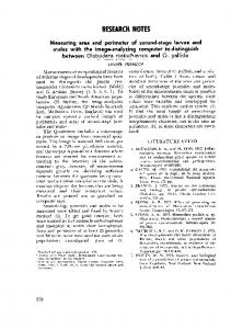
In Fig. 5, dm(i ) is the real distance between the intersections of area boundaries and the ith horizontal scanning line N v (i ) of the CCD. N m (i ) is the number of pixels between the intersections of area boundaries and the ith horizontal scanning line N v (i ) of the CCD. ds (i ) is the real distance between the intersections of rectangle path and the ith horizontal scanning line N v (i ) of the CCD. N s (i ) is the number of pixels between the intersections of area boundaries and the ith horizontal scanning line N v (i ) of the CCD.
In Fig. 5, (Q1 , Q2 , Q3 , Q4 ) which form a rectangle on the ground, are marked by the remote-controlled robot. The rectangle is centered in the picture along the line-of-sight. The distance between Q1 and Q2 is equal to the distance between
Q3 and Q4 . We obtain ds (i ) = ds( j ) = ds , which is
measured by the robot. According previous studies [10]-[13], the relationship between the pixel values and real distances are formulated as
dm(i ) =
N m (i ) × ds N s (i )
(2)
(3)
and
DH max ( j ) =
N H (max ) × ds N s (i )
N H (max ) × ds N s ( j)
for the jth horizontal scanning line.
SC
N v (i ) ΔH (i, j )
Nv ( j)
ΔAPT (i, j )
Q1
Q2
Ns (i ) Ns ( j ) Nm( j ) Nm(i )
0
0 NH (max)
Fig. 5 the relationship of distance and pixel for area measurement. Assume that the horizontal field of view of the CCD is 2θ H . The distance ΔH (i, j ) between the ith
horizontal scanning line N v (i ) and the jth horizontal scanning line N v ( j ) is:
ΔH (i, j ) =
1 [DH max (i ) − DH max ( j )]× cot θ H (6) 2
The area between the ith horizontal scanning line
N v (i ) and the jth horizontal scanning line N v ( j ) in ΔAPT (i, j ) =
1 [dm(i ) + dm( j )]× ΔH (i, j ) , (7) 2
where i = j + m , and m is the number of scanning
for the jth horizontal scanning line. Similarly, the maximum distance at the ith horizontal scanning line N v (i ) of the CCD is
DH max (i ) =
IAPT
the irregular area IAPT is
for the ith horizontal scanning line, and
N ( j) dm( j ) = m × ds N s ( j)
NV (max) Q3
Q4
lines between N v (i ) and N v ( j ) . In Figure 6, the total area around the irregular path can be accumulated using k smaller rectangles: (4)
k −1
MAPT = ∑ ΔAPT (i, j ) . i =1
(5)
(8)
166
Proceedings of the 2007 WSEAS Int. Conference on Circuits, Systems, Signal and Telecommunications, Gold Coast, Australia, January 17-19, 2007
1 N H (max ) 2 Q3
Q4 i =1
m
SC
1 NV (max ) 2 N v (i ) Nv ( j)
k ×m
i = k −1
Q1
Q2
Fig. 6 the total area around the irregular path can be accumulated using k smaller rectangles.
(a) Measured result = 11.7519 m 2 Error = -6.4817%
4. Experimental Results The radius of the robot wheel in this paper is 5 cm, and the reflector plate generates 30 pulses per wheel rotation, so that the distance measurement resolution is π/3 cm per pulse. Table 1 shows the measuring results and errors for 6 distances.
Table 1 Distance measurement Actual 50 100 500 1000 2000 5000 distance cm cm cm cm cm cm Measured 51 99 496 991 1993 4955 value cm cm cm cm cm cm Error % 2 1 0.8 0.9 0.35 0.9 Table 2 shows the area measuring results. Figures 7-8 shows the measured areas marked in red.
(b) Measured result = 12.7632 m 2 Error = -2.4126% Fig. 7 A circle of area with a radius of 2m.
Table (2) Area measurement Shape of area to be measured
Fig. 7a
Actual area Measured 2 value m Error %
4πm 11.751 9 -6.4817
2
Fig. 7b 2
4πm 12.763 2 -2.4126
Fig. 8a 2
Fig. 8b 2
16m
16m
14.5879
14.656
-8.8255
-8.4003
(a) Measured result = 14.5879 m 2 Error = -8.8255%
167
Proceedings of the 2007 WSEAS Int. Conference on Circuits, Systems, Signal and Telecommunications, Gold Coast, Australia, January 17-19, 2007
(b) Measured result = 14.656 m 2 Error = -8.4003% Fig. 8 A rectangle of area 16 m 2 to be measured. From Tables 1-2, we can see that we can obtain the distance and area measuring results from image without using any complex image identification method, and that the measurement error is acceptable in real situations.
5. Conclusions This paper proposes an innovative method for measurement and image recording at traffic accident sites. The method in this paper has proved to be feasible for irregular area measurement. A remote-controlled robot is used for distance measurement. Using the proposed measuring method, an irregular area can be measured directly without any complex image identification method, and that the measurement error is acceptable in real situations.
Acknowledgements: This work was supported by the National Science Council, Taiwan, under Grant NSC 95-2221-E-030-011. The authors would like to thank B. Schack for his useful comments and suggestions on improving this paper. References: [1] http://www.honestsensor.com.tw/ [2] http://www.omron.com.tw/ [3] A. Carullo and M. Parvis, “An ultrasonic sensor for distance measurement in automotive applications,” IEEE Sensors Journal,Vol.1, NO.2, pp.143-147-2001. [4] Alessio Carullo Franco Ferraris, and Salvatore Graziani, “Ultrasonic Distance Sensor
Improvement Using a Two-Level Neural Network,” IEEE Transactions on Instrumentation and Measurement, Vol. 45, No.2, pp.677-682, April 1996. [5] Y. M. KlimKov, “A laser polarmetric sensor for measuring angular displacement of objects,” in Proc. Eur. Conf. Lasers and Electro-Optics, Sep. 8-13, 1996, pp. 190-190. [6] H.-T. Shin, “Vehicles Crashproof Laser Randar,” M.S. thesis, Taoyuan, Opt. Sci. Center, Nation Central Univ., Taiwan, R.O.C., 2000. [7] H.Yan, “Image analysis for digital media applications,” IEEE Comput Graph. Appl., vol. 21, no.1, pp. 18-26, Jan.2001. [8] S. Paschalakis and P. Lee, “Pattern recognition in grey level image using mount based invariant features,” in Proc. Int. Conf. Image Processing and its Applications, vol. 1, 1999, pp. 245-249. [9] H.Yan, “Image analysis for digital media applications,” IEEE Comput Graph. Appl. ,vol.21, no.1, pp.18-26, Jan 2001. [10]M. C. Lu, Y. R. Hsu, and J. F. Tu,“Automobile SSD Alert System,”Distributed Multimedia System conf., Vol. 1, 2003, pp.806-809. [11] M.-C. Lu, W.-Y. Wang, and H.-H. Lan, “Image-based height measuring system for Liquid or particles in tanks, ”in Proc. IEEE Int. Conf. Networking,Sensing and Control, Vol. 1, 2004, pp.24-29. [12] M.-C. Lu, “Vorrichtung zum Messen des Fűllstands von Lagergut, ”German patent of invention, No.20319293.1, 2003. [13] Ming-Chih Lu,Wei-Yen Wang,and Chun-Yen Chu, “Image-Based Distance and Area Measuring System,” IEEE Sensors Journal, Vol. 6, No.2, pp.495-503, April 2006.
168