Retrieving from a Panorama Database by SURF ... SURF is applied to feature matching between omni- .... cess Spaces from the Ministry of Education, Culture,.
Image Based View Localization System Retrieving from a Panorama Database by SURF Naoyuki Yazawa, Hideaki Uchiyama, Hideo Saito Keio University 3-14-1 Hiyoshi, Kohoku-ku 223-8522, Japan {yazawa,uchiyama,saito}@hvrl.ics.keio.ac.jp Myriam Servi`eres, Guillaume Moreau Ecole Centrale de Nantes - CERMA IRSTV Rue de la No¨e, BP 92101, 44321 Nantes Cedex 3, France {myriam.servieres,guillaume.moreau}@ec-nantes.fr
Abstract We propose a system for estimating a user’s view direction with its location of a captured image by retrieving its corresponding region from panoramas in a database. In our database, 104 panoramas captured within a local area are stored. For retrieving a user’s location, the query image captured by the user’s planarprojection camera is compared with all the panoramas in the database. SURF is used for finding corresponding points between the query and each panorama. The panorama which gets maximum number of corresponding points is selected as the location. In addition, a user’s view direction is also estimated by reprojecting the center of the query onto the selected panorama. As a result, image based view localization with panoramas can be achieved.
1
Introduction
Image based outdoor localization has been addressed for autonomous navigation vehicles and recording human activities. Compared with indoor localization, the outdoor localization should overcome change of weather, season and time in a complex scene including moving objects such as cars or humans. In the field of sensor based outdoor localization, various methods have been proposed with different levels of accuracy, computational costs. The most widelyused device is GPS attached on a mobile device such as a mobile phone. GPS can provide a position with good accuracy but its stability and coverage are poor according to places in practice. WiFi is an alternative device based on radio waves but its achievable accuracy depends on the distribution of beacons [3]. Recently, image based outdoor localization has often been discussed [10, 7, 11]. Development and widespread use of camera-equipped mobile devices such as a mobile phone are remarkable. In addition, large image databases of urban areas are provided by many companies such as Google. Computer vision technology using these environments may provide higher accurate positioning. For this reason, image based outdoor localization has become an alternative approach against sensor based outdoor localization. Image based outdoor localization is mainly achieved by using local feature matching between a query image
and images in a database. Some rich descriptors for the features have been proposed with a high dimensional vector such as SIFT [6], SURF [1], which are robust to the changes of illumination, rotation and scale. The descriptors are also used for outdoor object recognition such as buildings [12, 4, 8]. SIFT based feature matching was used for finding corresponding points between a query image and images tagged by GPS locations in a database [11]. From the images in the database, two corresponding images to the query are selected from the maximum number of the corresponding points. Since the two images have location information, the camera pose of the query can be computed from the two images by triangulation. SURF is applied to feature matching between omnidirectional images [7, 10]. Compared with SIFT, the authors conclude that SURF is better on accuracy and computational costs. Methods for hybrid localization with a camera and some sensors have also been proposed [9, 2]. They use sensors in order to get a rough user’s location at first. By using feature matching with edges between a query image and images in a database of the limited area by sensors, the accuracy of the user’s location is improved against using only sensors. In these works, only estimation of a user’s location has been discussed. However, a user’s view direction is also important information, which represents what the user is looking at. In our work, we would like to focus on the method for the estimation of the user’s view direction with its location by image matching between the panorama in the database and the query captured by the user’s planarprojection camera which is the difference between previous works [7, 10]. The rest of the paper is organized as follows: we will introduce our proposed system and environmental settings in Section 2. We will then explain the details of our algorithm in Section 3. In the experimental results, the influence of the changes of weather, time and captured positions for our algorithm will be discussed in Section 4.
2 2.1
Proposed System Overview
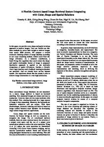
Our system can provide a user’s view direction with its location by comparing a query image captured by
the user and panoramas in a database. In related works, omnidirectional images are used [7, 10] as an image database. In our work, a panorama generated by many images is used. Though existing panorama databases are available such as Google Street View, we have built our own database described in Section 2.2 in order to focus at first on the estimation of a user’s view direction with its location. In our assumption, a user’s camera has GPS in order to get a rough location, which accuracy is at worst 1 km as [9, 2]. This assumption allows panoramas to be captured within 1 km radius from the user’s location. Our work focuses on the estimation of the user’s view direction with its location after the area is limited by GPS or any another knowledge. When using our system, a user who wants to know where he/she is captures a query image and sends it to the database at first. The database returns the panorama of the closest point of a place where the query was captured with a viewing direction (Figure 1).
(a) Our device
(b) Configuration
(c) Sources for (d)
(d) Panorama by (c) Figure 2: Acquisition of Panoramas
Figure 1: System Overview
2.2
Acquisition of Panoramas
Figure 2(a) and (b) describe the device we used in order to acquire panoramas. The device has a digital camera, a tripod, a protractor and a compass for capturing an image accurately at even intervals. The device can measure an angle with a 1 degree resolution by the protractor for recording a direction from which each image is captured. The camera platform can move horizontally. For making a panorama, we capture 18 images at 20 degree intervals in order to avoid distortion (Figure 2(c)). After capturing the images, we use a free software ”Image Composite Editor” by Microsoft in order to generate a panorama (Figure 2(d)). The left side and right side of the generated image is 0 degrees, which means north.
3 3.1
Algorithm Overview
As a pre-processing, SURF features’ database of each panorama is generated beforehand. In an on-line processing (Figure 3), SURF features of a query image is computed and matched with SURF features of each panorama individually. The panorama which gets the maximum number of matched points is selected as a user’s view location. In addition, a user’s view direction is estimated by reprojecting the center of the query onto the selected panorama.
3.2
Figure 3: On-line Processing panorama of a query image based on SURF feature matching. As a pre-processing, a SURF feature of each keypoint computed by fast hessian detector is stored in the database as (Panorama ID, x, y, SURF descriptor), where Panorama ID means the captured location, (x, y) is the coordinate of the keypoint in the panorama and SURF descriptor is a 128 dimensional vector. From a query image captured by a user, SURF keypoints are extracted and their SURF features are computed (Figure 4(a)). SURF features of the query are compared with SURF features of each panorama individually (Figure 4(b)). Since each panorama gets the number of matched points, the panorama which gets the maximum number of the matched points is selected as a user’s view location. As a result, the place information such as an address can be presented because each panorama has the information where the panorama was captured.
3.3
Estimation of User’s View Direction
Retrieval of User’s View Location
In the first step, our system retrieves a user’s location from a database by finding a corresponding
In the next step, our system estimates a point of gaze in the selected panorama as a user’s view direction. For estimation the point of gaze, the center of
4.2
(a) Keypoints in a Query
(b) Keypoints in a Panorama Figure 4: SURF keypoint
the query is reprojected onto the panorama. From the matched points by SURF, the homography matrix between the query and the selected panorama can be calculated. Since there are some wrongly matched points, RANSAC process is inserted into the calculation of the homography matrix. By homography matrix, the center of the query can be reprojected onto the panorama (Figure 1). In addition, the query image frame can be also reprojected onto the panorama. For providing a user’s view direction as a degree, our system can compute the degree of the projected query center on x-axis because the left side and right side of the generated image was 0 degrees (Figure 1).
4 4.1
Experimental Results Settings
We captured 104 panoramas at intersections (red squares) in the part of Yoshikawa city of Japan as a database (Fig.5). The average radius of intersections was 8m. In this area, intersections exist at most in every 40 meter. Since the intersections are sometimes close each other, a building is captured in several panoramas. In all following experiments, query images are captured at X, which is names of following sections. We discuss the influence of where and when queries are captured. The size of each query is 320 × 240 pixels and each panorama is 1680 × 250 pixels. Since SURF feature matching between the query and a panorama took 4 seconds, the whole process with 104 panoramas took around 400 seconds.
Query images were captured at the location where their corresponding panorama was captured. The time for capturing the query and panoramas is same. The query is not included in the images for generating the corresponding panorama. The accuracy of the retrieval of view location was 100%. Since the location where the query was captured and the location where the corresponding panorama of the query was captured were same, the precise degree of the view direction can be computed. In Figure 6, the ground truth of the direction from which a query was captured was measured beforehand by using our device. Since the average difference of degrees between the ground truth and estimated direction was 1.2 degrees, we can estimate a user’s view direction accurately in the case that the location where a query image is captured and the location where a panorama was captured were same.
Figure 6: Estimated View Direction
4.3
Different Location
Query images were captured between 1m and 10m away from the location where the corresponding panorama of the query was captured in order to evaluate a tolerable location range where a query can be captured (Figure 7). On an average, the estimation of user’s view direction with its location was succeeded in the case of the distance between 1m to 7m (Figure 7). The scale of captured objects changes according to the change of the distance betweem a camera and objects. Since SURF is robust to the change of scale, the estimation was achieved with several locations. However, the estimation failed around 8m because the change of scale was large.
4.4
Night
220 query images were captured at night. Images for all the panoramas were captured at daytime. The color and brightness of a texture may change depending on the time. The success rate of the estimation of a user’s view direction with its location was 34 %. In Figure 8(a), the textures of the board at night is the same as that at daytime thanks to its backlight. If there are street lamps, the success rate of the estimation increases. If there is no light source, the estimation may be failed because textures at night is drastically different from textures at daytime (Figure 8(b)).
4.5 Figure 5: Panoramas at Intersections (map from [5])
Same Location
Different Time and Location
This experiment includes the condition of Section 4.3 and Section 4.4. 80 query images were captured.
(a) 1m
(a) Success
(b) 5m
(b) Failure of View Direction Estimation Figure 9: Different Time and Location Queries
(c) 7m Figure 7: Different Ranges
of the query onto the selected panorama. In the experimental results, the success ratio decreased in case of different light conditions. In the future, our system will use panorama databases provided by many companies such as Google.
Acknowledgement This work is supported in part by a Grant-in-Aid for the Global Center of Excellence for high-Level Global Cooperation for Leading-Edge Platform on Access Spaces from the Ministry of Education, Culture, Sport, Science, and Technology in Japan. (a) Success
(b) Failure Figure 8: Night Queries The success rate of the estimation of a user’s view direction with its location was 32 %. If the difference of lighting condition between a query and panoramas was small, the estimation succeeded (Figure 9(a)). In one of the failure cases, the retrieval of a user’s location succeeded but the estimation of the view direction failed (Figure 9(b)). Since there are wrongly matched points, the view direction cannot be estimated in case of few matched points.
5
Conclusions
We proposed an outdoor localization system for providing a user’s view direction with its location from a captured image. The estimation of the view direction was achieved by retrieving the corresponding panorama of the captured image in a database. For retrieving a user’s location, the query image captured by the user’s planar-projection camera was compared with all panaramas by SURF feature matching. The panorama which gets maximum number of corresponding points was selected as the location. In addition, a user’s view direction was also estimated by reprojecting the center
References [1] H. Bay, A. Ess, T. Tuytelaars, and L. V. Gool. SURF: Speeded up robust features. CVIU, 110:346–359, 2008. [2] C. Cappelle, M. El Badaoui El Najjar, D. Pomorski, and F. Charpillet. Localisation in urban environment using GPS and INS aided by monocular vision system and 3D geographical model. In Proc. IV, pages 811– 816, 2007. [3] Y.-C. Cheng, Y. Chawathe, A. LaMarca, and J. Krumm. Accuracy characterization for metropolitan-scale wi-fi localization. In Proc. MobiSys, pages 233–245, 2005. [4] G. Fritz, C. Seifert, and L. Paletta. Urban object recognition from informative local features. In Proc. ICRA, pages 131–137, 2005. [5] Geographical Survey Institute. http://www.gsi.go.jp/index.html. [6] D. G. Lowe. Distinctive image features from scaleinvariant keypoints. IJCV, 60:91–110, 2004. [7] A. Murillo, J. Guerrero, and C. Sagues. SURF features for efficient robot localization with omnidirectional images. In Proc. ICRA, pages 3901–3907, 2007. [8] H. Shao, T. Svoboda, and L. van Gool. HPAT indexing for fast object/scene recognition based on local appearance. In Proc. CIVR, pages 71–80, 2003. [9] U. Steinhoff, D. Omerˇcevi´c, R. Perko, B. Schiele, and A. Leonardis. How computer vision can help in outdoor positioning. In Proc. AmI, pages 124–141, 2007. [10] C. Valgren and A. J. Lilienthal. SIFT, SURF and seasons: Long-term outdoor localization using local features. In Proc. ECMR, pages 253–258, 2007. [11] W. Zhang and J. Kosecka. Image based localization in urban environments. In Proc. 3DPVT, pages 33–40, 2006. [12] W. Zhang and J. Kosecka. Hierarchical building recognition. IVC, 25:704–716, 2007.