TechBase
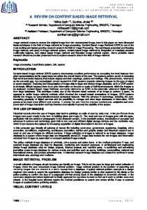
Image Content Engine for Finding Rings of Defects on Optics n prior years, LLNL’s Image Content Engine (ICE) project produced a fast, robust technique for finding patterns in images, called GDM (Gradient Direction Matching). This algorithm differs from other template matching algorithms in that it correlates a template with an image after both are first transformed into images containing only gradient direction information (Fig. 1).
I
Project Goals Our goal was to customize and apply the GDM technique from ICE to support one of the optics inspection requirements for the National Ignition Facility (NIF): finding rings of defects on optics (FRODO). Our objective was to augment the NIF Optics Inspection analysis capabilities
Laura M. Kegelmeyer (925) 422-0924
[email protected]
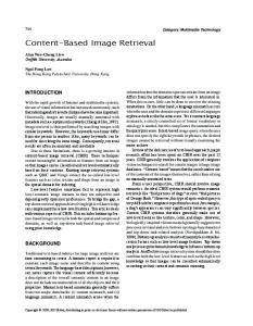
(which finds in-focus defects in images of the NIF optics) by finding indirect evidence of defects for which we cannot physically focus the cameras. The indirect evidence we want to find is the diffraction ring pattern that is formed downstream of the interaction between a plane wave of the illuminating laser light and the spherical wave of the obscuring defect (Fig. 2). The resulting ring pattern will match with the custom luminance disk template when both are transformed into gradient space and correlated with the GDM technique. Once diffraction rings are found, we can incorporate our knowledge of the ring location with predictions about defects that are not in focus and we can also improve our confidence metrics for defects that we can detect directly.
Figure 1. Luminance disk matching. Top: diffraction ring pattern (left) and corresponding direction flow field (right). Bottom: luminance disk model image (left) and corresponding gradient direction flow field (right). Arrows point in direction from dark to light.
116
FY06 Engineering Research and Technology Report
Engineering Systems for Knowledge and Inference The GDM technique has already been beneficial to several areas within the NIF directorate. One is to find diffraction rings, as planned. Another, unexpected benefit is that it also robustly and effectively finds halos in off-beamline laboratory images needed to verify the quality of optic coatings. BioSciences, NDE, and Chemistry are other areas where the FRODO results can be usefully applied to find circular features in complex images.
FY2006 Accomplishments and Results This year saw successful completion of the project milestones, from the initial concept to the final characterization of FRODO for NIF Optics Inspection. We produced tools to create a training set and to generate Receiver Operating Characteristic (ROC) curves in order to evaluate algorithm performance. Then, we used an optimization program, APPSPACK, to optimize parameters used in the FRODO codes. Optimized parameters were incorporated into FRODO and used to analyze the training set. An image showing detected rings is shown in Fig. 3.
The fringe contrast level ratio is R = (Imax– Imin)/(Imax+ Imin), where Imax and Imin are the maximum and minimum intensities, respectively. A ROC curve showing performance with different parameter settings is shown in Fig. 4, demonstrating the final success of the FRODO project. An additional effort is underway to incorporate these results into the NIF Optics Inspection Analysis process.
Related References 1. Paglieroni, D.W., W. G. Eppler, and D. N. Poland, “Phase Sensitive Cueing for 3D Objects in Overhead Images,” Defense & Security Symposium, Proc. SPIE, 5809, Orlando, Florida, March 2005. 2. Chen, B. Y., L. M. Kegelmeyer, J. A. Liebman, J. T. Salmon, J. Tzeng, and D. W. Paglieroni, “Detection of Laser Optic Defects Using Gradient Direction Matching,” SPIE Photonics West LASE Symposium: 8th International Workshop on Laser Beam and Optics Characterization, Proc. SPIE, 6101, January 21-26, San Jose, California, 2006. 3. Kolda, T., and G. Gray, et al., Asynchronous Parallel Pattern Search, Sandia National Laboratories, http://software.sandia.gov/appspack.
Figure 3. Image from a camera focused on a main laser power amplifier, with diffraction rings labeled with colored circles: blue circle indicates a ring with fringe contrast level ratio irradiance above a value of 0.15; red circles have fringe contrast level ratio irradiance below 0.15.
1 DR 15 DR 25 DR 5
0.8 True positive
Relevance to LLNL Mission
0.6 0.4 0.2 0
Plane wave (laser)
r
Opaque scattering source Irradiance (r) Distance to image plane z
Upstream laser optic Interference intensity pattern
0
0.2
0.4 0.6 False positive
0.8
1
Figure 4. ROC curve for the results of FRODO analysis for an image of a main laser power amplifier. The three separate curves were obtained using three different radii for the luminance disk radius (DR) in the GDM algorithm. A y-axis value of 1 indicates that all labeled rings in the image were identified, whereas a value less than 1 indicates that FRODO did not find all the labeled rings. The graphs show that FRODO finds large, clear rings easily, but has trouble with fainter rings when using a larger disk radius size.
Downstream laser optic
Figure 2. Diffraction ring patterns arising from the interference between a plane wave and an opaque scattering source, e.g., a defect scattering site.
Lawrence Livermore National Laboratory
117