Jul 5, 2007 - Immunet can be applied to arbitrary topologies, either regular or irregular, exhibiting in ..... 5 show different cases for an intermediate node, a.
IEEE TRANSACTIONS ON COMPUTER, TC-2007-07-0304
1
Immunet: Dependable Routing for Interconnection Networks with Arbitrary Topology Valentin Puente, Jose Angel Gregorio, Fernando Vallejo, and Ramon Beivide Abstract— A complete mechanism for tolerating multiple failures in parallel computer systems, denoted as Immunet, is described in this paper. Immunet can be applied to arbitrary topologies, either regular or irregular, exhibiting in both cases graceful performance degradation. Provided that the network remains connected, Immunet is able to deal with any number of failures regardless of their spatial and temporal distribution. Our mechanism operates on the basis of a dynamic network reconfiguration in response to failures. The network reconfiguration only employs local information recorded at the router nodes which leads to a highly scalable system. In addition, its low cost and overhead permit a practicable hardware implementation. Finally, as Immunet does not require in-flight traffic to be discarded, the parallel applications running in the system can transparently circumvent network failures. Only packets stored in or traveling through a broken component need to be recovered by higher system levels. Index Terms— Parallel systems, fault-tolerance, interconnection networks, routing, packet deadlock.
—————————— ——————————
1 INTRODUCTION
————————————————
• The authors are with the Computer Architecture Group, Universidad de Cantabria, ETSIIT, Avda. Los Castros s/n, 39005 Santander (Spain). Email: {vpuente, monaster, vallejof, beivider}@unican.es.
and the available hardware resources are sufficient to circumvent the situation, it is common to use the software approach because of its lower implementation cost. However, if faults arise frequently or the state after the fault compromises network survivability, the hardware approach seems a more convenient solution. The two solutions operate at a different system level and can be used in conjunction to rescue the system. At network level, after a fault, packet routing and deadlock avoidance mechanisms are no longer valid. Thus, if no solution is provided, the whole network can be blocked in a short time period. The possible solutions range from disabling healthy resources [1] to just adapting the deadlock avoidance scheme to the new network topology.
Th0 Th1 Accep. Load (f/c)
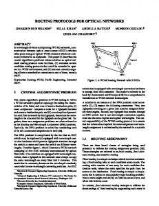
HE large number of processors and interconnection devices present in current parallel computers negatively affects their fault probability. Specifically, failures in the interconnection network can isolate an important part of the machine with healthy processors that could otherwise be used. In certain scenarios, the Mean Time Between Failures (MTBF) can be lower than the execution time of some typical applications running on the system. Such is the case of the IBM BlueGene/L supercomputer [1]. One of the most complex problems for handling link and/or node faults is that such faults induce topological alterations greatly affecting the routing and deadlock avoidance mechanisms of the network. Therefore, it is essential to design interconnection networks with suitable mechanisms for guaranteeing message delivery, even in these critical scenarios. In general, a fault-free interconnection network is able to support a maximum packet throughput Th0, as represented in Fig. 1. Let us suppose that, at time t0, a fault arises. If appropriate mechanisms to tolerate the fault are provided, after a certain period tr, the parallel system should recover and continue working in a degraded but effective operation mode. The performance degradation, Th0-Th1, is caused by the resource loss and by the changes in the resulting network topology. An adequate faulttolerant system must provide minimum overhead in fault-free conditions. Moreover, both performance loss after fault (Th0-Th1) and tr should be as low as possible. Fault tolerant techniques can be classified as hardwarebased and software-based. When the failure rate is low
Accepted Load (f/c)
T
Failure (t0)
tr
0 0
Time (Cycles)
Time (cycles)
Fig. 1. Throughput degradation: transitory and stationary phases.
In this paper, we present Immunet, a new faulttolerant parallel system able to manage any combination of failures in an interconnection network using Virtual Cut-Through (VCT) flow control, [18], and Adaptive Bubble Routing (ABR), [25]. The seminal work describing the basis of this mechanism was presented in [29][30]. Immunet can be applied using either regular or irregular networks, being able to support simultaneous and/or
Manuscript received (05 Jul. 2007) xxxx-xxxx/0x/$xx.00 © 200x IEEE
2
2 BASELINE ROUTER DESIGN Immunet is able to deal with arbitrary topologies either regular or irregular. In both cases, the network interconnects routers having d input links and d output links, d being the router degree. In regular networks, all the routers share the same degree but in irregular ones, d can change from router to router. Fig. 2 describes our basic router organization showing the usual hardware modules: crossbar, FIFO buffers, arbitration and routing logic, synchronization, etc. Routers inject packets from one or more computing elements to the network. Conversely, each router ejects packets from the network to one or more computing nodes. The router design has to maximize the use of the network resources avoiding communication anomalies such as packet deadlock, livelock and starvation. In order to support ABR our router has to have, at least, two virtual channels (FIFOs) per input link. In this work, we just consider the case of using two virtual channels: one for adaptively routed packets and another for statically routed ones. Upgrading the mechanism for using more virtual channels is straightforward. In ABR, a subset of the total virtual channels is configured as a safe virtual network in which packet deadlock never occurs, as in [24] and [10]. The remaining virtual channels are configured as a fully adaptive virtual network in which packet deadlock is not a concern. As long as there are available adaptive FIFOs, ABR always routes packets
through the adaptive network. Safe FIFOs are only requested when all the profitable adaptive FIFOs are exhausted which causes the blocking of all the adaptive routing alternatives. From local hosts
Sync.
Crossbar
Sync.
From other routers
ROUTER
SC Table
Arbiter R.U.
To local hosts or other routers
nested failures. Moreover, a system shutdown and reboot are not necessary even after the occurrence of any combination of failures. All these features can be easily implemented in the network hardware with near zero impact on its performance under fault-free conditions. The failure type considered in this paper is a permanent fault, which is modeled as a “fail-stop” one, reflecting that some component (link or node) stops functioning. It is also assumed that the neighboring nodes of a faulty component will be able to detect, after a finite time that such a component is out of service. If the failing component were a bidirectional link, the two routers incident to it will detect the failure provided that both of them are alive. If the failing component is a node, all its adjacent operational routers will detect it. A node failure can be seen, in fact, as a multiple failure of all of its incident links. Consequently, our proposal will be based just on local information registered at the individual nodes. The rest of this paper is organized as follows. In Section 2 the baseline router design will be presented. Then, in Section 3 the Immunet basis consisting in finding a spanning tree embedded in the network will be described. Section 4 is devoted to the selection of a unique spanning tree among all those possible. In Section 5, the whole Immunet routing is described. Next, in Section 6, one of the multiple implementations of Immunet is considered. Section 7 includes a complete performance evaluation analysis of Immunet. In Section 8, the most relevant related work is reviewed and finally, in Section 9, the main conclusions of this work are summarized.
IEEE TRANSACTIONS ON COMPUTER TC-2007-07-0304
Adap Safe Table Table
Fig. 2. Basic Router Organization.
A fault-tolerant ABR router supporting two virtual channels employs three tables to route packets. Two of them are standard routing tables having as many rows as the number of system nodes. The Adaptive Table governs packet routing inside the adaptive virtual network and the Safe Table does the same in the safe one. With current hardware technology, the network scalability is not compromised by the size of these tables. Their initialization is carried out at boot time as in the SGI Spider [11] or the 21364 Alpha [21]. Our router also employs another Safe Connectivity (SC) table that records the current connectivity of the safe network topology. The SC table size is proportional to the router degree. In order to obtain a global idea of our scenario, let us consider a k-ary 2-cube as a particular example. As shown in Fig. 3a, this network can be seen as a collection of 4k unidirectional rings of length k (2k rings in each dimension). As two virtual channels are employed per physical link, both the safe and the adaptive virtual networks will be composed of 4k rings of k FIFOs each. The rings belonging to the safe and the adaptive virtual networks are denoted as safe and adaptive rings, respectively. In ABR, packets move under two different policies. In the adaptive virtual network, the injection and transit of packets are regulated by VCT flow control [18]. Packets in transit inside any of the safe rings are also regulated by VCT. However, packet incorporation to the safe virtual network is restricted by Bubble Flow Control (BFC). BFC is a deadlock-avoidance mechanism applicable to topologies based on either a single ring or a set of rings visited under Dimension Order Routing (DOR), [5]. Packets can be injected inside a safe ring from three sources: a computing node, the adaptive virtual network or another safe ring of a previous dimension. BFC only permits the incorporation of packets to a safe ring if they do not exhaust the FIFOs belonging to that ring. In this way, there will always be, at least, one free buffer inside the ring (a Bubble under our terminology) which assures packet movement. This routing algorithm is currently used by IBM BlueGene/L supercomputers [1].
PUENTE ET AL.: INMUNET: DEPENDABLE ROUTING FOR INTERCONNECTION NETWORKS WITH ARBITRARY TOPOLOGY
router x 0 1
3 2 In/out ports
(a)
SC Table In\out 0 1 2 3
0 1 0 0 0 0 1 0 0 1 (b)
2 1 0 0 0
3 0 1 0 0
Fig. 3. (a) Fault-free 4×4 Torus and Safe paths inside the router. (b) Safe Connectivity Table.
Continuing with the example, Fig. 3b shows a SC table, which reflects the shape of the safe virtual network topology crossing an arbitrary router in a 4×4 Torus. The table has been updated according to the port labeling described in Fig. 3a. The content of this SC table reflects a fault-free torus. In absence of failures, all the nodes will have this same content in their tables. A bit set to one in row i and column j of the SC table indicates that a packet queued at the static FIFO of input port i can be forwarded through output port j when there is room for the packet at the neighboring router (VCT). Any other packet attempting to select the output port j must fulfill the Bubble protocol that imposes the existence of room for, at least, two packets in the safe FIFO of input port j (BFC).
3
of a deadlock-free safe path to interchange packets among all the surviving nodes. Finding this unique ring is based on a classical result from Graph Theory stating that there is always a spanning tree in any connected graph. In response to each network failure, our mechanism will be able to find a unique spanning tree embedded in the resulting network. A pre-order tour through this spanning tree will provide the safe ring which connects all the operational routers. Before describing in the next Section the way in which the safe ring is obtained, let us continue with the previous example. Fig. 4 shows a spanning tree obtained from our 4×4 torus after failing three of its 32-bidirectional links. In the fault-free network there were 128 profitable transit FIFOs (64 adaptive and 64 safe). Now, there will be only 116 usable FIFOs as the other 12 are unreachable due to the failure of the 3-bidirectional links. As the tree is composed of the 16 routers and 15 bidirectional links, the directed safe ring will be composed of 30 FIFOs connected through 30 unidirectional links. This set of resources constitutes the safe ring. In addition, there will be another 86 reachable FIFOs, which will constitute the adaptive virtual network. 12
13
14
15
8
9
10
11
4
5
6
7
0
1
2
3
(a)
14
(b)
13
2
9
1
6
8
5
10
15
3
12
11
0
7
3 IMMUNET BASIS One of the most complex problems for handling any combination of link and/or node faults is that these faults induce topological changes affecting the deadlock avoidance mechanism of the network. For example, a fault in any link of a torus breaks two unidirectional rings and, therefore, it is not always possible to use DOR to route packets through the safe virtual network. Then, the first requirement that our system must guarantee is that, independently of the number and configuration of faults, there is always a deadlock-free path to route packets among the surviving nodes. To do that, Immunet will successively update the SC routing tables which reconfigure the topology of the safe network in response to the failures. The key idea is to always provide a unidirectional ring traversing, once or more, all the surviving system nodes. The particular connectivity of this ring in each node will be recorded in its SC table. Applying BFC over packet injections on this single ring will guarantee the existence
4 12
8
13
14
15
9
10
11
(c) 4
5
6
7
0
1
2
3
Fig. 4. Example of a safe ring after three faults in the network.
It is easy to see that for building the safe ring it is enough that any node in the tree knows who its parent is and who its children are. Every router can record the current safe ring topology just maintaining a d-bit register with ones in those positions corresponding to links connecting either to its parent or to any of its children. In a
4
IEEE TRANSACTIONS ON COMPUTER TC-2007-07-0304
fault-free network the d-bit registers will be set to zero. Fig. 5 show different cases for an intermediate node, a root and a leaf. A simple cyclic traverse through this register will determine the safe ring’s local connectivity and thus, the position of the ones contained in the SC table.
ch0 ch1 ch2 ch3 1 1 1 1
ch0 ch1
ch2
ch3
In\out 0 1 2 3
0 0 0 0 1
1 1 0 0 0
2 0 1 0 0
3 0 0 1 0
(a)
ch0 ch1 ch2 ch3 0 1 1 1
ch0
ch1
ch3
In\out 0 1 2 3
0 0 0 0 1
1 1 0 0 0
2 0 0 0 0
3 0 1 0 0
(b)
ch0 ch1 ch2 ch3 1 0 0 0
ch2
In\out 0 1 2 3
0 0 0 0 0
1 0 0 0 0
2 0 0 1 0
3 0 0 0 0
(c)
Fig. 5. Creation of new passages after fault detection. (a) An intermediate node. (b) Root node. (c) Leaf node.
4 LOOKING FOR A UNIQUE SAFE RING In this Section, the search for the spanning tree over which relies the Immunet safe ring is considered. We contemplated separately the cases of a single failure, multiple failures and finally, nested ones.
4.1 Single Failure Healthy routers have the ability to enter in an emergency state after detecting the failure through any of their operational ports. Routers in emergency will buffer inflight packets and temporarily stop data communications. Then, they enter in a reconfiguration mode and propagate the failure detection to their neighbors. All the routers manage a local register denoted as RS (Reconfiguration Status) that will be updated after failure detection and propagation. In a fully operational network all the RSs will be set to zero. When the failure is detected, the RS will be set to the value of its ID node number. After that, the router will propagate the emergency state to all of its operative neighbors signaling such a state and sending its local RS. Once received by a neighbor, the incoming RS will be compared with the local one. If the
local RS is higher, no more actions will take place. Otherwise, the local RS will be updated to the value of the incoming RS and the emergency state will be propagated to all the remaining neighbors. Any node propagating a failure must wait a finite time that depends on the particular router implementation, until receiving an acknowledgment from all of its hypothetical children. No answer from a neighbor after this time-out means that such a node is not a child of the current one. After this time-out, the router will have updated its d-bit register and its SC table. After finishing the reconfiguration process, every node except the root will have a unique parent and a set of children; obviously, leaf nodes will have no children. Table 1 shows the detection and propagation failure algorithms for this simple case. To prove the correctness of this algorithm we have to consider two cases; firstly, the ideal case in which just one router detects the failure and secondly, the more realistic case in which several routers detect it. In the first case, the root node (the only one detecting the failure) will perform a broadcast communication sending its RS to all the remaining network nodes. As all of them will have a lower RS (all are initially set to zero), they become children of the root node. The parenthood relations among intermediate nodes will depend on the order in which they receive the emergency state, which depends on technological details of the router and network implementation. It is worthwhile to note that no router changes its local RS more than once. Any intermediate node will adopt the first received RS. If a new propagation of the same failure is sent again by another router, as the received RS will be the same as the local one, no more reconfigurations will take place. Hence, our mechanism self-stabilizes after the finite time required by the broadcast communication, which only depends on the network diameter and on the underlying implementation technology. Let us now consider the case in which several routers detect the single failure. Although our reconfiguration algorithm does not need to know the root node, note that it will be the router with higher ID detecting a single link failure. In the case of a faulty router, the root will be the neighbor router with the highest ID. In both cases, several reconfiguration processes looking for a unique tree will start departing, at most, from d routers, d being the maximum network degree. It is easy to see that, in the worst case, an arbitrary router will change its RS, at most, d times. At the end of the reconfiguration process, just one tree will succeed. To proof this assertion, let us suppose the contrary. If more than one tree were embedded in the network, more than one root with the same RS would have to exist, which is impossible by construction. Consequently, the worst case time for obtaining a unique safe ring is clearly bounded.
4.2 Multiple Sequential Failures We will now examine the more complex case in which multiple sequential failures exist. In order to maintain our system working after an arbitrary sequence of failures, we have to guarantee the existence of only one tree in the network for building the safe ring. To achieve that, we
PUENTE ET AL.: INMUNET: DEPENDABLE ROUTING FOR INTERCONNECTION NETWORKS WITH ARBITRARY TOPOLOGY
DETECTION ALGORITHM: When failure then Buffer incoming packets Stop data communications RS=ID Propagate the faulty state sending a signal plus RS to all neighbors Wait a finite time-out for children response and update d-bit register Register the link number who connects to its first Child
PROPAGATION ALGORITHM: If Local_RS