Implementation of SiC inverter for high frequency, medium voltage applications Oleg Sivkov*, Martin Novak † † * ††
CTU in Prague, FME, Dep. of Instrumentation and Control Engineering, Prague, Czech Republic,
[email protected] CTU in Prague, FME, Dep. of Instrumentation and Control Engineering, Prague, Czech Republic,
[email protected]
Abstract—This paper describes the experiments with a custom build high frequency SiC inverter. The inverter uses the CCS050M12CM2 module with SiC MOSFET (1200V, 50A). A comparison of SiC MOSFET and Si IGBT modules both from datasheets and different scientific papers showed that SiC MOSFETs have higher efficiency, smaller losses and are capable to work with higher frequency than Si IGBTs. The characteristics of SiC MOSFET and Si IGBT inverter were measured in our laboratory and showed that SiC MOSFET had smaller power static losses and switching losses than Si IGBT, SiC MOSFET had higher efficiency and can operate under higher switching frequency than Si IGBT. The switching characteristics of SiC module have been measured up to a frequency of 30 kHz. The problem of gate-source voltage overshoot is considered here; it is caused by parasitic capacitances and inductances. The correct value of damping resistor is tuned to suppress overshoot. Keywords: Silicon-based power devices, SiC MOSFET, switching losses, voltage overshoot, damping resistor
I.
INTRODUCTION
Silicon-based power devices (primarily MOSFETs) have dominated applications in power electronics. They have widespread applications in power electronics converters for industry, aerospace applications, hybrid and electric vehicles, etc. Due to this fact there is an increasing need for devices that are capable of faster switching, higher power rating, lower switching losses, and higher temperature capability. SiC unipolar devices such as MOSFET can today replace Si IGBT at high voltage levels. This paper investigates the CCS050M12CM2 module. It will be used to control a highspeed permanent magnet synchronous motor. It can operate at very high frequencies, much higher than IGBT. However the higher the switching frequency of the converter the higher the switching losses. The purpose of this paper is to develop a high-frequency SiC converter with reduced switching power losses and higher frequency capability so it could have higher efficiency and use the smaller heat sink. The comparison between inverters realized with SiC MOSFET and Si IGBT is introduced in paper [1]. These two types of inverter are compared under the same DC link supply voltage. Those results show that SiC MOSFET inverter has the following parameters: loss on main switch devices 76.02 W, loss on diodes 0.54 W, total loss 76.56 W, efficiency 99.40%; and Si IGBT inverter parameters: loss on main switch devices 342.97 W, loss on diodes 5.14 W, total loss 348.12 W, efficiency 97.08%. The comparison was done for frequency
20kHz. Thus SiC MOSFET inverter has higher efficiency and smaller total losses. The comparison between SiC MOSFET and Si IGBT are also investigated in paper [2]. The efficiency of SiC MOSFET is 99% at frequency 20 kHz and 98.5% at 40 kHz; the efficiency of Si IGBT is 98.5% at 20 kHz and 97.6% at 40 kHz. MOSFET conduction loss is 20.4 % at 40 kHz and IGBT conduction loss is 30.4 %. Thus the results show that the SiC MOSFET inverter has higher efficiency and lower conduction loss at the same switching frequency. SiC MOSFET and Si MOSFET inverters are also compared in paper [3]. It was found that at switching frequency 100 kHz the efficiency of SiC inverter was 89.5 % and of Si inverter 82.2 %; at output power 400 W the efficiency of SiC and Si inverter is 96.5 % and 94 % respectively. The function of SiC MOSFET and Si IGBT for wind turbine applications is compared in paper [4]. The simulation results show that at switching frequency 50 kHz SiC converter efficiency is 85% and Si IGBT converter efficiency is 44%. A SiC based motor drive with a new SiC JFET transistor (to minimize conduction and switching losses) is proposed in paper [5]. At average power input 1131.21 W for both inverters the SiC inverter power loss is 14.21 W and efficiency is 98.74%, the Si inverter has 104.13 W power loss and 91 efficiency; Si inverter requires volume 2624 cm3 and mass 7269 g, SiC inverter volume is 337 cm3 and mass 935 g. Thus the simulation results in paper [6] show that SiC inverter has less power loss, higher efficiency, requires smaller heatsink and has other significant advantages in comparison to Si inverter. The losses of a Si-based PWM inverter and a SiC-based PWM inverter are compared in paper [7]. The results show that the SiC-based converters need less cooling because of superior material characteristics and because of smaller losses than the Si-based converter. A simplified loss model, which enables users to calculate converter losses based on datasheet values is proposed in paper [8]. The design and test results for a three phase high frequency SiC inverter are presented in paper [9]. At 100 kHz the inverter efficiency was measured 97%, at 400 kHz the efficiency was 91%.
The zero voltage switching (ZVS) performance of a 1200 V SiC MOSFET, 1200 V Si IGBT and 900 V CoolMOS MOSFET is evaluated and compared in paper [10]. The experimental results showed that MOSFET, PT IGBT, FST IGBT and CoolMOS had total turn-off time: 52 ns, 270 ns, 236 and 114 ns respectively. The further results calculated in MATLAB showed that MOSFET, PT IGBT, FST IGBT and CoolMOS had ZVS turn off loss 0.046 mJ, 0.525 mJ, 0.42 mJ and 0.255 mJ respectively. Thus according to the research in paper [10] MOSFET has more favorable device parameters than parameters of the other devices for achieving zero voltage switching performance. Investigation of 1.2 kV SiC MOSFET is realized in paper [11]. SiC MOSFET is compared with SiC JFET and Si CoolMOS, the advantages and disadvantages of the SiC MOSFET are summarized in this paper. The results show that SiC MOSFET although it suffers from higher switching loss than Si CoolMOS due to larger capacitance, has lower total power loss due to its low on-resistance. A full-bridge inverter using 3.3kV/6A SiC MOSFET is presented in paper [15]. The simulation and experimental results show that fast switching and high voltage make the converter performance and switching losses quite sensitive to parasitic capacitances. The impact of parasitic capacitances has been investigated in this paper. The performance of SiC MOSFET inverter that is based on the module CCS050M12CM2 is investigated in this paper. The main goals of this paper are to test these inverter characteristics and to achieve the reduced losses of the inverter at high switching frequency. The characteristics of our SiC inverter under static conduction and dynamic switching states are presented in this paper. The static characteristic are realized at power supply voltage up to 33 V and current up to 30 A. The dynamic characteristics were tested up to: 200 kHz, 30 V, 13 A.
TABLE II.
PARAMETERS OF SKM75GD124D (SI) IGBT MODULE
Symbol
Parameter
Value
Unit
VDS
Drain - Source Voltage Collector Current Junction Temperature Turn-on delay time Turn-off delay time
1200
V
75 150
A ˚C
60 420
ns ns
IC TJ td(on) td(off)
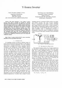
Tab. 2 shows selected parameters of the SKM75GD124D IGBT module. Comparing the parameters of these two modules that operate under the same input supply voltage we can see that CCS050M12CM2 module has 3 times shorter turn-on delay time and 8 times shorter turn-off delay time than SKM75GD124D module. The only advantage of IGBT module as we see from their parameters is that it can operate under the higher load current. However our application - permanent magnet synchronous motor doesn't consume higher value of current but do operate mainly under the higher frequencies. B. Comparison from experimental results In second step the measured characteristics of both modules are compared. Fig. 1 shows the tested circuit for both modules. In this circuit the source voltage is changed from + 5 V to 33 V. Voltmeter measures the voltage drop Vds of the transistor VT2, ampere meter A measures the load current of this transistor. The current is changed from zero to 30 A by increasing the source voltage and reducing the resistors R1 and R2. Only the bottom transistor in the half-bridge is controlled, the TOP1 transistor is left closed at all times.
COMPARISON OF SIC AND IGBT MODULES
II.
A. Comparison from datasheet In first step the performance of SiC and IGBT module are compared from datasheet. Tab. 1 shows selected parameters of SiC MOSFE module CCS050M12CM2. TABLE I.
PARAMETERS OF THE CCS050M12CM2 (SIC) MODULE.
Symbol
Parameter
Value
Unit
VDS
Drain - Source Voltage On State Resistance
1.2
kV
25 ... 34
mΩ
59
A
150 21 50
˚C ns ns
RDS(on) ID TJ td(on) td(off)
Continuous Drain Current Junction Temperature Turn-on delay time Turn-off delay time
Figure 1. Testing scheme of MOSFET inverter
Figure 3. Voltage drop and power static losses as function of current Id for CCS050M12CM2 and SKM75GD124D modules
Figure 2. Voltage drop and power static losses as function of current Id for CCS050M12CM2 and SKM75GD124D modules
III.
MEASURING RESULTS OF SIC MODULE AT HIGHER CURRENT VALUES
The characteristics of SiC inverter are measured for values of current 4 and 5A. Fig.2 shows the measured results of voltage drop Vds and static power losses on transistor current Id for CCS050M12CM2 module. This dependence shows that the voltage drop is increased with raising the load current and hence the losses are increased as well. There is also a small dependence of the voltage drop on the supply voltage, but above around 15 V, the voltage drop stays the same for the same value of current. Fig.2 also shows the dependence of collector-emitter voltage Vce on collector current Ic for SKM75GD124D module. The dependence is measured only at Vsource=30V for this module. The difference between voltage drops of these modules show that IGBT module has approximately 1.3 V higher than SiC module and therefore SKM75GD124D has higher static losses than CCS050M12CM2 module. Thus the practical experiments showed that SiC MOSFET module has smaller losses than IGBT module.
The conduction and switching losses are measured in these characteristics. Same as in previous measurement the transistor BOT1 is supplied with the rectangular pulses with variable frequency from a pulse generator. The waveforms of voltage and current were measured by the oscilloscope Tektronix from where switching losses were determined. Voltage and current waveforms are depicted in fig. 4. Switching and conduction losses are calculated using the oscilloscope Tektronix.
Fig. 3 shows the switching on and off losses depending on switching frequency for SiC and IGBT modules. For this experiment the BOT1 transistor was supplied with rectangular pulses with variable frequency from a function generator. The switching losses were measured with a Tektronix TPS2024 oscilloscope with the TPS2PWR1 power application software. It can be seen that the off switching loss is significantly higher than the on switching loss in both types of modules. The losses of SiC module are significantly lower than the losses of IGBT module; especially off losses. Figure 4. Turn on and off switching waveforms for SiC module with f=5kHz I=4A
Figure 5. Switching on losses as the function of switching frequency of SiC module
Fig. 5 and fig. 6 show the switching on and off losses depending on switching frequency for different values of load current - 4 A and 5A. With increasing frequency the losses increase. The higher the value of load current the larger the losses are. The conduction losses as the function of frequency shown in fig. 7 remain approximately same with increasing frequency.
Figure 7. Conduction losses as the function of switching frequency of SiC module at load current 4A
IV.
ANALYSIS OF THE DRIVER CIRCUIT
Another very important problem of high frequency converters is the reduction of gate-source voltage overshoot of the MOSEFTs during switch on and off transient states. These overshoots are caused by the presence of parasitic capacitances and inductances creating an RLC circuit. When this circuit is not tuned correctly, the overshoot and undershoot can impose high stress on the transistor and even cause its failure. To dampen the transistor overshoot the correct value of the resistor should be set at the output of the driver. The higher value of the resistor dampens the oscillations but the higher the resistor, the higher the Joule loss in it. Therefore, the value of the resistor has to be tuned to provide fast switching and low delay but to limit the loss. In order to optimize the driver circuit, to analyze its behavior and to prevent excessive voltage overshoot the analysis of the circuit was done. The model of the circuit used for the analysis is shown in fig. 8. This circuit can be described by a set of equations:
Rg int ⋅ ( I g + I1 ) +
1 ( I g + I1 )dt + C gate ∫
(1)
+ R112 ⋅ I1 = 0 Figure 6. Figure 6. Switching off losses as the function of switching frequency of SiC module
1 1 ( I g + I 2 + I 3 )dt + I 2 dt = 0 ∫ C111 C110 ∫
(2)
Figure 8. Circuit substitution diagram
1 1 ( I g + I 2 + I 3 )dt + I 3 dt = 0 ∫ C111 C109 ∫
(3)
The parameters Rout_driver, Rgin, Cgate have been obtained from the manufactured datasheets. The PCB traces inductivity was calculated from the PCB trace geometry as follows. Lpcbtrack1 and Lpcbtrack2 are PCB tracks over a ground plane, theirs inductance can be estimated:
Figure 9. Calculated response of model circuit
L≈
μ0 μr h W
(for W >> h, h>>t)
(4)
Where W is the trace width, h is trace height above ground plane and t is trace thickness Lpcbtrack3 is trace inductance of parallel conductors, it inductance is estimated as
L≈
μ0 μr d cosh −1 π W
(for d>>W, W>>t)
(5)
Where W is trace width, d is trace center distance and t is trace thickness. The obtained values are shown in fig. 8. The given set of equations (1)-(3) was solved, the current Ig was calculated. The simulation results calculate directly voltage Vgate through the current Ig. Fig. 9 shows the simulation results of gate-source voltage waveform. The experimentally obtained response for the same input frequency 210 kHz is shown in fig. 10. From the comparison it can be seen that the calculated response matches well the experimental considering the simplicity of the model and all the other neglected parasitic components in the real circuit neglected in the model.
Figure 11. Gate voltage waveforms with Rdamp=11.7Ω
The single parameter that can be tuned in this circuit is the damping resistor Rdamp. Tuning this resistor yielded an optimal value of Rdamp = 11.75 Ohm. This provides enough damping, but assures a fast enough response. It was experimentally determined that for a higher frequency (1 MHz) the optimal damping is slightly higher. The experimentally obtained waveforms for 200 kHz PWM frequency that will be used in the final application are shown in fig. 11. The experimental prototype of SiC inverter is in the fig. 12. SiC inverter CCS050M12CM2 is intended for high-frequency applications. Transistor BOT1 was supplied predominantly from the function generator with pulses. The transistor drivers were supplied from an independent source. The SiC module with its heatsink is under the main board; therefore we can't see it in the picture.
Figure 12. Photo of testing circuit diagram of SiC MOSFET inverter
V.
CONCLUSIONS
This paper investigates CCS050M12CM2 module characteristics. The proposed inverter was tested up to the switching frequency of 30 kHz. After comparison of the parameters of SiC MOSFET and Si IGBT modules from datasheets, other scientific papers and our experiments it is clear that MOSFETs have much smaller switching time delay, SiC has smaller losses and much higher efficiency than IGBTs. Therefore there is no doubt that for the experiment with high-speed permanent magnet synchronous motor the SiC MOSFET is more appropriate than Si IGBT. The experimental results showed that off losses are almost ten times higher than on losses at switching frequency 20 kHz.
Figure 10. Gate voltage waveforms with small Rdamp
The analysis of driver circuit was realized to prevent the voltage overshoot at the output of the driver. The differential equations of circuit substitution diagram were set up and solved to determine the damping resistor to suppress the overshoot. Finally a correct value of the resistor was tuned to damp the overshoot and retain fast switching and low delay.
In future research the investigated CCS050M12CM2 module is to be used for an experimental high-speed permanent magnet synchronous motor. ACKNOWLEDGMENT This work was supported in part by the CTU internal grant SGS12/178/OHK2/3T/12 „Development of measuring, simulation and experimental methods with focus on nontraditional energy source“. REFERENCES [1]
Di Han; Noppakunkajorn, J.; Sarlioglu, B., Analysis of a SiC ThreePhase Voltage Source Inverter Under Various Current and Power Factor Operations, Industrial Electronics Society, IECON 2013 - 39th Annual Conference of the IEEE , vol., no., pp.447,450, 452, 10-13 Nov. 2013 [2] Gangyao Wang; Fei Wang; Magai, G.; Yang Lei; Huang, A.; Das, M., "Performance comparison of 1200V 100A SiC MOSFET and 1200V 100A silicon IGBT," Energy Conversion Congress and Exposition (ECCE), 2013 IEEE , vol., no., pp.3230, 3234, 15-19 Sept. 2013 [3] Yamane, A.; Koyanagi, K.; Kozako, M.; Fuji, K.; Hikita, M., "Fabrication and evaluation of SiC inverter using SiC-MOSFET," Power Electronics and Drive Systems (PEDS), 2013 IEEE 10th International Conference on , vol., no., pp.1029, 1030, 1032, 22-25 April 2013 [4] Hui Zhang; Tolbert, L.M., "Efficiency Impact of Silicon Carbide Power Electronics for Modern Wind Turbine Full Scale Frequency Converter," Industrial Electronics, IEEE Transactions on , vol.58, no.1, pp.21, 23, 26, 28, Jan. 2011 [5] Chang, H.-R.; Hanna, E.; Radun, A.V., "Development and demonstration of silicon carbide (SiC) motor drive inverter modules," Power Electronics Specialist Conference, 2003. PESC '03. 2003 IEEE 34th Annual , vol.1, no., pp.211, 213,214, 216 vol.1, 15-19 June 2003 [6] Hui Zhang; Tolbert, L.M.; Ozpineci, B.; Chinthavali, M.S., "Power losses and thermal modeling of a 4H-SiC VJFET inverter," Industry Applications Conference, 2005. Fourtieth IAS Annual Meeting. Conference Record of the 2005 , vol.4, no., pp.2630,2634 Vol. 4, 2-6 Oct. 2005 [7] Ozpineci, B.; Tolbert, L.M.; Islam, S.K.; Hasanuzzaman, M., "Effects of silicon carbide (SiC) power devices on HEV PWM inverter losses," Industrial Electronics Society, 2001. IECON '01. The 27th Annual Conference of the IEEE , vol.2, no., pp.1061,1066 vol.2, 2001 [8] Miaosen Shen; Krishnamurthy, S., "Simplified loss analysis for high speed SiC MOSFET inverter," Applied Power Electronics Conference and Exposition (APEC), 2012 Twenty-Seventh Annual IEEE , vol., no., pp.1682,1687, 5-9 Feb. 2012 [9] Miaosen Shen; Krishnamurthy, S.; Mudholkar, M., "Design and performance of a high frequency silicon carbide inverter," Energy Conversion Congress and Exposition (ECCE), 2011 IEEE , vol., no., pp.2044,2049, 17-22 Sept. 2011 [10] Kadavelugu, A.; Baliga, V.; Bhattacharya, S.; Das, M.; Agarwal, A., "Zero voltage switching performance of 1200V SiC MOSFET, 1200V silicon IGBT and 900V CoolMOS MOSFET," Energy Conversion Congress and Exposition (ECCE), 2011 IEEE , vol., no., pp.1819,1826, 17-22 Sept. 2011 [11] Honggang Sheng; Zheng Chen; Wang, F.; Millner, A., "Investigation of 1.2 kV SiC MOSFET for high frequency high power applications," Applied Power Electronics Conference and Exposition (APEC), 2010 Twenty-Fifth Annual IEEE , vol., no., pp.1572,1577, 2125 Feb. 2010 [12] Harada, K.; Maki, K.; Pounyakhet, S.; Tokiyoshi, J.; Kozako, M.; Ohtsuka, S.; Hikita, M., "Switching characteristics of SiC-VJFET and manufacture of inverter," Power Electronics Conference (IPEC), 2010 International , vol., no., pp.176,179, 21-24 June 2010
[13] Xun Gong; Ferreira, J.A., "Investigation of Conducted EMI in SiC JFET Inverters Using Separated Heat Sinks," Industrial Electronics, IEEE Transactions on , vol.61, no.1, pp.115,125, Jan. 2014 [14] Hui Zhang; Tolbert, L.M., "Efficiency of SiC JFET-Based Inverters," Industrial Electronics and Applications, 2009. ICIEA 2009. 4th IEEE Conference on , vol., no., pp.2056,2059, 25-27 May 2009 [15] Rixin Lai; Lei Wang; Sabate, J.; Elasser, A.; Stevanovic, L., "Highvoltage high-frequency inverter using 3.3kV SiC MOSFETs," Power Electronics and Motion Control Conference (EPE/PEMC), 2012 15th International , vol., no., pp.DS2b.6-1,DS2b.6-5, 4-6 Sept. 2012 [16] Matocha, K.; Losee, P.; Glaser, J.; Nasadoski, J.; Arthur, S.; Stevanovic, L., "Getting the most from SiC MOSFETs: Optimizing conduction and switching losses for high performance power electronics applications, [17] Stevanovic, L.D.; Matocha, K.S.; Losee, P.A.; Glaser, J.S.; Nasadoski, J.J.; Arthur, S.D., "Recent advances in silicon carbide MOSFET power devices," Applied Power Electronics Conference and Exposition (APEC), 2010 Twenty-Fifth Annual IEEE , vol., no., pp.401,407, 21-25 Feb. 2010 [18] Mostaghimi, O.; Wright, N.; Horsfall, A., "Design and performance evaluation of SiC based DC-DC converters for PV applications," Energy Conversion Congress and Exposition (ECCE), 2012 IEEE , vol., no., pp.3956,3963, 15-20 Sept. 2012 [19] Puqi Ning; Fei Wang; Ngo, K.D.T., "Forced-Air Cooling System Design Under Weight Constraint for High-Temperature SiC Converter," Power Electronics, IEEE Transactions on , vol.29, no.4, pp.1998,2007, April 2014