728
IEEE ELECTRON DEVICE LETTERS, VOL. 29, NO. 7, JULY 2008
SiC Varactors for Dynamic Load Modulation of High Power Amplifiers Mattias Südow, Hossein M. Nemati, Mattias Thorsell, Ulf Gustavsson, Kristoffer Andersson, Christian Fager, Per-Åke Nilsson, Jawad ul Hassan, Anne Henry, Erik Janzén, Rik Jos, and Niklas Rorsman
Abstract—SiC Schottky diode varactors with a high breakdown voltage, a high tuning ratio, and a low series resistance have been designed and fabricated. These characteristics are particularly necessary for the dynamic load modulation of high power amplifiers (PAs), which is an attractive alternative to other efficiency enhancement techniques. For a SiC Schottky diode varactor with a 50-µm radius fabricated by using a graded doping profile, a breakdown voltage of 40 V, a tuning range of 5.6, and a series resistance of 0.9 Ω were achieved. The results show the great potential of this type of varactors for the use in the dynamic load modulation of high power amplifiers. Index Terms—Dynamic load modulation, Schottky, SiC, varactor.
I. I NTRODUCTION
T
HE HIGH peak-to-average ratio in modern telecommunication signals requires elaborative methods for improving the average efficiency of the power amplifiers (PAs) used. Dynamic load modulation has recently been suggested as a means of improving the average efficiency of PAs [1], [2]. The architecture is realized by a variable matching network using electronically tunable elements such as varactors. There are, however, challenges in realizing suitable varactors for high power transmitter applications. The most important specifications are a large and linear capacitance tuning range, low series resistance, linearity, and high breakdown voltage [3]. The first two properties are necessary to achieve a wide dynamic range and avoid losses in the varactor, respectively. A nonlinear C–V characteristic of a varactor has two disadvantages for high power transmitter applications. First, the capacitance is not only controlled by the applied bias, but it is also affected by the large RF voltage swing. With twoManuscript received March 6, 2008; revised April 15, 2008. This work was supported in part by the Swedish Governmental Agency of Innovation Systems (VINNOVA), by the Swedish Energy Agency (STEM), by the Chalmers University of Technology, by Ericsson AB, by the Furuno Electric Co. Ltd., by Infineon Technologies Nordic AB, by the Norse Semiconductor Laboratories AB, by Norstel AB, by NXP Semiconductors BV, and by Saab AB. The review of this letter was arranged by Editor Y. Taur. M. Südow, H. M. Nemati, M. Thorsell, U. Gustavsson, K. Andersson, C. Fager, P.-Å. Nilsson, and N. Rorsman are with the Microwave Electronics Laboratory, Chalmers University of Technology, 412 96 Göteborg, Sweden (e-mail:
[email protected]). J. ul Hassan, A. Henry, and E. Janzén are with the Department of Physics and Measurement Technology, Biology and Chemistry, Linköping University, 581 83 Linköping, Sweden. R. Jos is with the Microwave Electronics Laboratory, Chalmers University of Technology, 412 96 Göteborg, Sweden, and also with NXP Semiconductors BV, 5656 Eindhoven, The Netherlands. Color versions of one or more of the figures in this letter are available online at http://ieeexplore.ieee.org. Digital Object Identifier 10.1109/LED.2008.2000642
tone excitation, this results in the generation of intermodulation products [3]. Second, a very nonlinear or hyper abrupt C–V characteristic implies that most of the tuning range is available in a narrow low-voltage region. Outside this region, the capacitance is constant. This effectively limits the tuning range of the varactor for high power applications, because a large RF swing will bring the varactor into its forward conducting region [1]. In [3], custom-made silicon-on-glass varactors are proposed for use in dynamic load modulation transmitters. A uniform doping profile is combined with an antiseries configuration to minimize the distortion from the varactor [3]. The breakdown voltage is 12 V, which limits its application to handset and low power applications. In high power applications, a high breakdown voltage of the varactor is the most important parameter. To improve the high power handling capabilities, Lepine et al. suggest SiC varactors for high power applications [2]. The benefit of using a SiC varactor diode lies in the critical field, which is roughly one order of magnitude higher than that in Si or GaAs. This can be illustrated by comparing the series resistance in a SiC Schottky diode to that of a Si or GaAs Schottky diode with the same voltage rating. A 100-V SiC diode could be realized with a doping concentration as high as 5 × 1017 cm−3 and an epitaxial thickness of only 0.45 µm. The corresponding Si and GaAs diodes would have a doping of 3 × 1015 cm−3 and 6 × 1015 cm−3 , respectively, with epitaxial thicknesses of 6.5 and 4.8 µm, respectively. For the same anode area, the Si and GaAs diodes would have a series resistance of almost 400, respectively 25 times that of the SiC diode. This letter presents the design and implementation of SiC varactors for use in dynamic load modulation PAs. It is shown that special considerations in the design of this type of varactors allow satisfactory results. The varactor technology is presented in Sections II and III. In Section IV, the measurement results are presented and compared with a commercially available high voltage Si-based varactor. II. E PITAXIAL D ESIGN AND G ROWTH The diode structure consists of an epitaxially grown depletion layer on top of a highly doped SiC substrate. The concept for improving the tuning range is to introduce a graded doping profile to linearize the square root dependence for uniformly doped diode structures. In this letter, a gradient with an x−3 profile has been evaluated (Fig. 1). The improvement in tuning range was analyzed analytically by a double integration of the charge density in the depletion region, resulting in an implicit expression for the C–V
0741-3106/$25.00 © 2008 IEEE
SÜDOW et al.: SiC VARACTORS FOR DYNAMIC LOAD MODULATION OF HIGH POWER AMPLIFIERS
729
Fig. 3. Schematic picture of the SiC Schottky diode structure and a device photograph of the fabricated component.
Fig. 1. Specified x−3 graded doping profile and the C–V -based measurement of the doping profile.
Fig. 4.
Fig. 2. Calculated C–V profiles for SiC Schottky diodes with uniform and graded doping profiles together with the measured C–V characteristics for the fabricated SiC Schottky varactor and a hyper abrupt high voltage Si varactor diode (normalized to the same zero bias junction capacitance).
characteristics. With the x−3 falling profile, a considerable improvement in tuning range is achieved (Fig. 2). A horizontal hot-wall CVD reactor [4] was used for the growth of the n-type doped epilayers. The growth temperature and pressure were 1560 ◦ C and 200 mbar, respectively. The Si and C sources were silane and propane (C/Si = 1) with hydrogen as a carrier gas and nitrogen as the n-type dopant. An unintentional up ramping of the growth rate during the initial 10 min of growth has earlier been observed, which influences the dopant incorporation in the epilayer [5]. The typical growth rate is generally in the range of 3 to 5 µm/h; however, in this letter, a lower growth rate is used to allow better control of the desired thickness (0.5 µm), increasing the growth time to 13 min. To be able to increase the nitrogen doping level from 4 × 1016 cm−3 at the substrate/epilayer interface to 4 × 1017 cm−3 at the epilayer surface and with the specified graded x−3 doping profile (Fig. 1), a special schema for the flow of N2 gas was developed. III. C OMPONENT D ESIGN AND F ABRICATION A circular diode structure was chosen to minimize edge effects. Diodes with anode radii of 25 and 50 µm were made
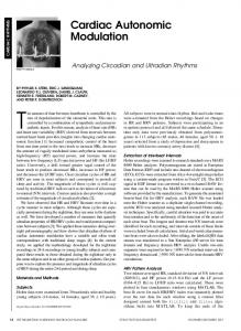
Extracted capacitance and Q-value at 2 GHz for a 50-µm-radius diode.
to enable deembedding of extrinsic elements. A coplanar structure was used to enable on-wafer measurements. The cathode contact was placed on the topside to reduce the series resistance associated with the substrate. The anode was defined through mesa etching. A 800-Å SiO2 surface passivation was grown by thermal oxidation at 1150 ◦ C for 8 h in a tube furnace in an O2 atmosphere. Ohmic contacts were made through Ni deposition and subsequent annealing at 1000 ◦ C for 5 min in an Ar atmosphere. A 0.5-µm field oxide was deposited to minimize substrate-associated capacitances, and vias to the anode and cathode were etched. A Ti/Au (500/3500 Å) Schottky contact was deposited, and a coplanar probe pattern was defined by using Ti/Au (300/3600 Å). The probe pads were electroplated, and an air-bridge was formed to contact the anode (Fig. 3). IV. C HARACTERIZATION The diodes were characterized by combined I–V (0 to −30 V) and S-parameter (10 MHz to 40 GHz) measurements, using a VNA and external source meters. At −30 V, the 50-µm-radius SiC Schottky diode has a leakage current of 15 µA, which is equivalent to 2 nA/µm2 . A complementary I–V measurement showed a breakdown voltage of 40 V. The junction capacitance and the series resistance were extracted by using low frequency S-parameters (1–5 GHz) to reduce the effects from parasitic elements. The zero bias junction capacitance of a 50-µm-radius diode was 9 pF, and the series resistance showed a nearly bias independent behavior with a typical series resistance of 0.9 Ω. The Q-value at 2 GHz for this diode is shown in Fig. 4.
730
IEEE ELECTRON DEVICE LETTERS, VOL. 29, NO. 7, JULY 2008
The performance of the SiC Schottky diode was compared to a commercially available hyper abrupt Si varactor diode with a comparable breakdown voltage (Micrometrics, MTV 406011/19 [6]). This diode had a zero bias junction capacitance of 10 pF and a measured series resistance of 2 Ω. The effect of the x−3 profile is clearly seen as an improvement in the tuning range for biases down to −15 V. The SiC varactor has a capacitance ratio of 5.6, whereas the Si varactor has a capacitance ratio of 4.2 for the reverse voltage range of 0–15 V. The flat C–V response at increased reverse biases is due to the complete depletion of the graded epilayer. The considerably lower series resistance in the SiC diode will give a significant improvement of the Q-factor. V. D ISCUSSION AND C ONCLUSIONS The use of SiC Schottky diode varactors for the dynamic load modulation of high PAs has been suggested. This initial study shows the feasibility of SiC Schottky diodes designed for high tuning range, low loss, and high breakdown operation. A graded doping profile was successfully used to increase the tuning range and linearize the C–V characteristics of the varactor. By increasing the thickness of the graded epilayer even further, a tuning ratio of more than ten will be possible. The high critical field of SiC enables considerably higher doping levels than in Si or GaAs varactors at the same bias
rating. This means that the loss in SiC varactors will be lower and the Q-factor higher. With an increase of the epilayer thickness, the breakdown voltage of the component will be improved at the expense of a higher loss. A further improvement of the breakdown voltage can also be made through the use of self-aligned anode contacts, reducing the field crowding at the anode edge. ACKNOWLEDGMENT This research has been carried out in the GigaHertz Center and in the Microwave Wide Bandgap Technology project. R EFERENCES [1] F. Raab, “High-efficiency linear amplification by dynamic load modulation,” in Proc. IEEE MTT-S Int. Microw. Symp. Dig., Jun. 8–13, 2003, vol. 3, pp. 1717–1720. [2] F. Lepine, R. Jos, and H. Zirath, “A load modulated high efficiency power amplifier,” in Proc. 36th Eur. Microw. Conf., Sep. 2006, pp. 411–414. [3] K. Buisman, L. C. N. de Vreede, L. E. Larson, M. Spirito, A. Akhnoukh, T. L. M. Scholtes, and L. K. Nanver, “Distortion-free varactor diode topologies for RF adaptivity,” in Proc. IEEE MTT-S Int. Microw. Symp. Dig., Long Beach, CA, Jun. 2005, pp. 157–160. [4] A. Henry, J. Hassan, J. P. Bergman, C. Hallin, and E. Janzén, “Thick silicon carbide homoepitaxial layers grown by CVD techniques,” Chem. Vap. Depos., vol. 12, no. 8/9, pp. 475–482, Sep. 2006. [5] J.-U. Hassan, A. Henry, J. P. Bergman, and E. Janzén, “Epitaxial growth of thin 4H-SiC layers with uniform doping depth profile,” Thin Solid Films, vol. 515, no. 2, pp. 460–463, Oct. 2006. [6] [Online]. Available: http://www.micrometrics.com/pdfs/TV_60VAbr.pdf