IMPLEMENTATION OF STEP 224 IN AN AUTOMATED MANUFACTURING PLANNING SYSTEM R. Sharma and J.X. Gao* School of Industrial and Manufacturing Science Cranfield University, Cranfield, Bedford, MK43 0AL Email:
[email protected]
ABSTRACT: This paper reports the results of an on-going research project at Cranfield University in collaboration with a leading consultant company. A major objective of the research to develop a new generation process planning system using the latest tools and technologies, and to fully comply with the international standard for exchange of product data (STEP) Application Protocol 224 (AP224) for process planning using machining features. Although AP224 has been accepted as an international standard, there is a surprising lack of compatible software packages in the market. The developed prototype STEP-enabled Manufacturing Planning System (SMPS) can generate process plans and associated documents from AP224 files automatically, without any user interaction. The system consists of decision logic stored in an external database that makes it generic and compatible with any manufacturing application. A graphical tool is provided for knowledge/ logic capture. The system can also accept a feature tree generated using the Feature Model Editor (FME) which has been developed as an add-on to the system. FME is intended to be a tool for conceptual design of simple components. FME feature tree is used in the early design stage while the AP224 file generated from detailed design model is used in the later stages. The prototype system is intended for single piece machined (prismatic) parts and has been tested with case studies provided by the project collaborators. KEYWORDS: Manufacturing Planning, Knowledge Management, STEP, CAD/CAM
1
INTRODUCTION
Product delivery process is defined as the series of steps that take levels of product functional requirements, and using the tools and methods available, translate them into technically sound products that meet these requirements [1]. CAPP (Computer-Aided Process Planning) is the activity which links design with manufacturing. It is also the critical element in deciding the response time and accuracy of a flexible/ agile manufacturing system [2]. A major challenge in providing qualitymanufactured products on demand is the rapid creation of manufacturing plans, shop floor documents, routing slips and NC (Numerical Control) codes. The process planner has the essential and critical job of interpreting the design data and creating these documents. Computerised planning systems can help reduce planning time, and increase consistency and efficiency. But the main problem of transferring CAD (Computer-Aided Design) data to a downstream CAMP (Computer-
*
Corresponding author
Aided Manufacturing Planning) system is the lack of neutral formats as well as content to convey the CAD information. It has been universally recognised that geometric model of a part designed using conventional CAD systems is not sufficient for process planning or other reasoning and planning purposes [3]. Feature technology is an emerging tool for this purpose. Historically, the concept of a feature originated in process planning of machined parts. It therefore follows that linking CAD to CAMP for machined products using features has become the focus of numerous research efforts in recent years. A vast number of publications on feature technology are available. Gindy et al [4] provide a good literature review on the current state of feature technology. Feature-based product information model (for manufacturing planning) means identifying the design geometry in terms of holes, slots, pockets, bosses, fillets, chamfers and other design elements that can be machined. Manufacturing planning requires additional information such as the knowledge of the characteristic shape and features producible by the various processes, their dimensions, locations, tolerances and surface finish. The information should also cover more specialised factors such as tool accessibility, fixturing possibilities and inspectability. Many choices exist for creating feature models in a geometric-modelling context, such as automatic feature recognition, design by features [5], interactive feature definition/ identification, and parametric geometric modelling. Future CAD systems will no doubt use a combination of these techniques to achieve the aim of total system integration between design and manufacturing [6, 7, 8]. Manufacturing features can be directly related to the volumes or surfaces to be machined in various operations. More importantly, feature-based models complement knowledge-based manufacturing as machining features can be linked to corresponding machining logic. If features to be machined can be identified, explicitly or implicitly, the entire process of design to manufacturing has the potential to be fully automated. It is this direct association between a manufacturing feature and its realisation process that makes this field so attractive to researchers. Preparation of product (feature) data for computer-aided manufacturing planning is a difficult task, as features are domain dependent. This implies that the same design needs to be expressed in differing feature-based descriptions to satisfy different downstream applications. There have been attempts to extract data directly (Feature-based modelling) or indirectly (feature recognition) from the CAD database. In order to develop a procedure for consistent, unambiguous data abstraction from a generic data structure, the foundation or the standard on which the procedure is based is very crucial. ISO 10303 is the result of International Standards effort to develop such a neutral mechanism capable of completely representing the product data throughout the life cycle of a product. The emphasis of the research is the implementation of STEP Application Protocol 224 (AP224). The prototype STEP-enabled Manufacturing Planning System (SMPS) can generate process plans and associated documents from AP224 files automatically, without any user interaction. A graphical tool is provided for knowledge/ logic capture, which is stored in an external database. The system can also accept a feature tree generated using the Feature Model Editor (FME) developed as an add-on to the system. FME is intended to be a tool for conceptual design of simple components. FME feature tree is used in the early design stage while the AP224 file generated from detailed design model is used in the later stages.
2
2 2.1
STEP AND ITS APPLICATIONS Introduction to STEP
STEP, standing for STandard for the Exchange of Product Model Data, is officially titled ISO 10303 [9]. The International organisation for Standardisation has been working on this project since 1984 which is also one of its largest development efforts ever. The aim of STEP is to provide a representation of product information along with the necessary mechanisms and definitions to enable product data to be exchanged. The exchange of data is intended between different computer systems and environments associated with the complete product lifecycle including design, manufacture, utilisation, maintenance, and disposal. STEP represents an open standard to meet product data requirements over the entire life cycle of a product, including geometry, topology, tolerances, relationships, attributes, assemblies and configuration. To accomplish its ambitious goal, STEP has been constructed as a multipart ISO standard and is organised as a series of parts and each part is published separately STEP uses a formal specification language, EXPRESS [10], to specify the product information to be represented. EXPRESS is a data specification language that can be used to define data structures and constraints. It provides comprehensive facilities for the definition of entities, attributes and relationships in context of modular (multi-schema) data models [11]. The use of a formal language enables precision and consistency of representation and facilitates development of implementations. To transfer this information, STEP usually employs the neutral file approach. Transfer of data from one application to another is usually a two step process requiring an export and an import. The actual medium is an ASCII file. STEP covers a very wide range of products such as electronic, electro-mechanical, mechanical and sheet metal fabrications. STEP uses application protocols (APs) to specify the representation of product information for one or more applications. The APs define the scope, the information to be exchanged, the means of testing and a user guide for implementing the application. The nature of this description makes it suitable not only for neutral file exchange, but also forms a basis for implementing and sharing product databases and archiving. The ultimate goal is an integrated product information database that is accessible and useful for all the resources necessary to support a product. It is this characteristic which makes STEP computer sensible. It supports design reuse, data retention, and provides access to data across a product's entire life cycle. Fowler [12] and Pratt [13] provide a good introductory text on this subject. 2.2
STEP Application Protocols
The STEP Application Protocol of interest for this project is Application Protocol 224 [14] (Mechanical product definition for process planning using machining features). AP224 contains all the information needed to manufacture the required part including the materials, part geometry, dimensions and tolerances. The product definition in AP224 contains the shape representation as well as definition of the machining features. The definition also contains the initial shape of the material before machining. This is very important for production of valid process plans. This project mainly implements and tests AP224 for machining applications. Within AP224, the machining features are divided into 16 categories, such as boss, pocket, hole, slot and knurl. The standard also describes three different types of feature transitions namely, fillet, edge_round and chamfer. There is also a mechanism for describing a pattern of features. Each feature is 'explicitly' described using parameters. Union of one or more feature yields a compound feature. Features are constructed using a combination of profiles and paths. Profiles are 2D shapes and Paths are 3D. ‘Features’ are created by defining a profile over the entire length of a path. For example, a complete circular profile along a linear path defines a round hole. Several standard profiles, both open and closed are defined in the 3
AP. Several standard paths are also defined. A combination of these paths and profiles can be used to represent all the features. Tolerances are very important for manufacturing. AP224 caters for dimensional tolerances, size tolerances, location tolerances and geometric tolerances. The model description also contains various other miscellaneous manufacturing information like material, alternate material, material properties, notes and specifications. Administrative information about manufacturing of the part is also included in the model. The digital STEP definition AP224, used for individual mechanical components, carries all the necessary information to enable modern Computer Aided Manufacturing Planning systems to determine the optimum manufacturing route and machining process needed for both cost estimating and actual manufacturing with a high degree of automation [15]. 2.3
Application of STEP in Manufacturing
The commercial world is just beginning to embrace STEP as the standard for data exchange. Parametric Technology Corporation's Pro/ENGINEER® CAD system [16] was one of the first CAD systems to generate STEP AP203 data. This AP203 file contains a Boundary Representation (Brep) solid model of the Pro/ENGINEER® part model, as well as configuration management data. Other CAD systems like Unigraphics and I-DEAS are also beginning to provide facility to export/ import AP 203 files. There have been attempts to develop generic STEP based CAD systems and databases like the GPM (Generic Product Modelling) system proposed by Gu and Chan [17]. GPM system was designed and implemented according to the integrated resources of STEP. The GPM could integrate a variety of manufacturing activities in a concurrent engineering environment. An et al [18] propose an integration structure based on STEP as the central repository. Jardim et al [19] report on the SIP toolkit which is another initiative to enhance the adaptability and productivity of the commercial software tools utilising STEP. Usher [20] proposed an object-oriented paradigm for the representation of STEP data. The proposal however covered only STEP AP 224 product model for process planning and was not a generic integration product model. Other notable discussions on STEP implementations in the industry include [21, 22, 23]. There have been other academic implementations such as [24, 25, 26, 27]. Many researchers believe that the future of CAD-CAMP integration lies on the widespread acceptance of the STEP standard. The Generative Process Planning Environment (GPPE) system [2] is a STEP enabled process planning system from South Caroline Research Authority (SCRA) which provides feature-driven generative process planning capability for mechanical parts. SCRA developed a technique called Rapid Acquisition of Manufactured Part (RAMP) for the US Department of Defense [15], which demonstrated the feasibility of commercial implementation of STEP-based technology in industry. This technology was transferred to the UK navy in an attempt to make this the de-facto standard for the NATO armed forces. The UK Navy RAMP project was a pilot project supported by Naval Support Command [15]. The process planning software used in the project was LOCAM CAPP software from LSC Group UK, which was extended to use data from AP224 files and was also integrated with GraphCAM NC package. 3
THE STEP-ENABLED MANUFACTURING PLANNING SYSTEM (SMPS)
The final deliverable of this project is a STEP-enabled Manufacturing Planning System (SMPS) based on the AP224 protocol. It has been developed as suite of applications, which are linked to each other through intermediate files/ databases. This has been done for a number of reasons. Breakdown of the system into individual functional applications allows for better code development 4
and maintenance. Another advantage is that the individual applications can be upgraded as long as the intermediate file structure compatibility is maintained. The system can be run on different physical machines if the intermediate file drive is shared. For example, the AP224 viewer could be on the CAD workstations and the database editors could be installed on the PC of the process planner. Also the execution of the system could be done in a batch mode, i.e., the bulk files could be processed to get the intermediate and the post-processed files together. The overall flow of the application is shown in figure 1 as a block diagram. The physical disk files and applications are clearly marked in the diagram. Each function of the system will be further explained in this section.
FME Part File
AP 224 STEP File
NC Code AP224 Viewer
Logic Engine
Logic Designer
Resource Manager
Post-processor
Intermediate File
Manufacturing Database
CLIPS
Logic Database
Output Plan Database Configuration Files/ ROSE Library
Document Generator/ Viewer
Crystal Report Tempelates/ XML Stylesheets
Disk File
FINISHED PLAN (*.XML) Database
Program
FINISHED PLAN (*.RTF)
Figure 1: Program information flow
Each application needs to make a distinct boundary between the application itself and the data it uses. In this system, the Data Access Layer (DAL) has been compiled as a separate ActiveX Dynamic Link Library (DLL). This DLL exposes a single class, which provides the necessary methods and properties for all the bi-directional data access requirements of the program using standard Sequenced Query Language (SQL) calls. Making the appropriate changes to the DAL can easily accommodate any changes to the database schema. If binary compatibility is maintained with the older version, the main system using this DAL needs not be recompiled. All external file access is done using the data access layer. Windows NT®4.0 was selected as the base operating system, 5
although the compiled version has also been tested under Windows 95/98®. All executable applications have been developed in Visual BasicTM® 6.0 (Service Pack 5) and C++. 3.1
The AP224 Viewer/Reader
The AP224 viewer/reader (see figure 2) is an application for reading and viewing AP224 files. The application is capable of reading the AP224 file and displaying the solid model as well as displaying the feature tree of the component including all the attributes of the features. As shown in figure 2, the AP224 reader application window is divided into two panes. The left side of the pane displays the feature tree of the component whereas the right side displays the solid model. Clicking on a particular feature in the feature tree highlights the feature in the solid model. The feature can also be selected from the drop-down list in the toolbar.
Figure 2: AP224 viewer The STEP files, as discussed earlier are plain ASCII text files. These files are read into the viewer and displayed using ST-Developer from Steptools, Inc [28]. ST-Developer from StepTools Inc., is a set of Computer-Aided Software Engineering (CASE) tools that reduce the effort required in implementing STEP applications. ST-Developer includes programming libraries for working with EXPRESS information models and EXPRESS-defined data sets. ST-Developer tools can be used for information modeling, application development, and conformance checking for STEP files. STDeveloper contains programming environments that can be used to build software that works with STEP data in object-oriented databases, relational databases, and traditional files. An important component of ST-Developer is the ROSE C++ library. This library makes it possible for application programs to read, write, create, and manipulate STEP digital product information. This library has been used to develop the AP224 functionality of the system
6
3.2
The Logic Designer and Database
In the SMPS system shown in figure 1, the analytical logic, or more specifically the domain and empirical knowledge is kept in an external database. This logic can be edited and viewed graphically as a flowchart using the Logic Designer as shown in figure 3. The user also has the options of having multiple nested logic flowcharts. The point of entry into the logic, or the starting flowchart can be selected/ configured by the user. This is very convenient in case the same system
Figure 3: Logic Designer is to be used for different domains. For example, the user could develop the logic for process planning of prismatic mechanical parts and sheet metal parts as two separate flowcharts and use them as appropriate. Further flexibility is offered by allowing nesting of flowcharts. This approach to storing the logic has proved immensely successful not only in making the application flexible and updateable, but also helping in breaking down the domain specific barriers and making the application more generic. The application itself is only a shell to run the logic. Simple development of new analytical logic allows the application to be used in a completely new domain. The logic developed graphically using the Logic Developer is run (or executed) by the Logic Engine shown in figure 1. The logic is captured using a set of standard commands. The system provides an extensive vocabulary of commands for almost every situation. The system also provides commands for integrating with CLIPS expert system [29]. Acronym CLIPS stands for “C” Language Integration Production System. It was developed in the 1980s at NASA’s Johnson Space Centre to enable integration of state-of-the-art artificial intelligence and rule-based applications with existing ones. Component object (COM or COM+) technology [30] is used to enable the user to add more commands. A component is described as a reusable piece of software in binary form that can be 7
plugged into other components or software with relatively little effort. Using component software provides a much more productive way to design, build and reuse software [31]. 3.3
The Resource Manager and Manufacturing Database
The manufacturing database editor allows the user to edit and maintain the resources data and other tables in the database. The manufacturing database editor can be accessed as a standalone application or accessed from within the Logic Designer for easier navigation. This manufacturing database represents the empirical knowledge of the assembly-planning expert. Various types of resource tables are provided to hold data such as standard questions, explanation and help lines, operation macros and standard texts. It is also used to store the CLIPS rules. The system also provides a generic table similar to a spreadsheet in which any type of data can be structured and stored. There are various commands to interrogate the tables and use the data in them from within the flowchart or CLIPS rules. 3.4
The Logic Engine and post-processor
The logic engine is the heart of the system. It is responsible for actually running the logic stored in the logic database. The logic engine also processes and executes any calls to the CLIPS expert system. The logic engine uses the functionality of the AP224 viewer/reader to open AP224 file and generate a feature tree of the component in the memory. This feature tree is loaded into an internal memory data structure and can be interrogated by using the appropriate flowchart commands. For example, the developer could write a logic to load a AP 224 feature tree in the memory and then write a recursive loop to interrogate the features one-by-one and process them depending on their attributes. During a planning session, the Logic Engine runs the stored logic, retrieves the required data from the database and generates an intermediate file. The intermediate file contains macro calls and not the planning details. For example, if the requirement was to manufacture a hole feature
Figure 4: RTF and XML output from the planning system 8
using a drilling operation, the intermediate file would only have a call to the macro which contains the detailed operations for manufacturing the hole feature. These macro calls are translated into comprehensive detailed output by the post-processor. The NC code is also generated in a similar way. In fact the NC code is similar to any other planning document but is written out directly by the post-processor instead of being derived from an output database like the planning documents. 3.5
Generating and Directing the Output
The output of the logic postprocessor is an output plan database (see figure 1). This database is a relational database arranged in a hierarchy. Each output plan has a header section and a series of operations. Each operation has a series of detail lines for that operation. Each detail line has 10 Boolean flags corresponding to the 10 user defined documents. The Boolean flags are used for filtering the detail lines for generating the documents. The system is capable of generating the 10 user defined output documents either in Rich Text Format (RTF) files or as Extensible Mark-up Language (XML) [32] as shown in figure 4. The format and layout of RTF documents is decided by the report templates. The XML data is formatted for viewing using Extensible Stylesheet Language (XSL). Each XSL stylesheet describes rules for presenting an XML document source. XSL transformations can turn XML into a grammar and structure suitable for display in a browser and thereby make the output viewable on any hardware platform. The output in the form of RTF and XML documents offers tremendous flexibility in dissemination and annotation of the plans. The system also provides an output plan database editor. This editor allows the user to make minor changes directly to the output plan database and regenerate the output documents, rather than having to reprocess the AP224 file all over again.
Figure 5: Feature Model Editor 9
3.6
Feature Model Editor (FME)
The Feature Model Editor (FME) [33] has been developed as an alternate method of generating input for the planning system. Using AP224 as the input has its advantages but is restricted to detailed design stage as AP224 can be generated only from a detailed design model. FME consists of feature libraries, which can be edited by the user. The user can open only one library at a time although any number of part files can be opened simultaneously. The features in the library can be grouped into Families and Sub-Families. This allows for a more logical grouping of the features. The features inherit all the attributes of their parent family or sub-family. This minimises the number of individual feature attributes as most of the common attributes can be entered at family or sub-family level. Features also have a ‘picture’ attribute, which can be associated with a bit-map representing the feature. Feature instances can be added to the part by simple drag-and-drop operations. The features can also be repositioned within a part using the drag-and-drop operation. The application also provides facilities for cut-and-paste operations. When imported into the planning system, each feature in the tree has a check box that can be used for include or exclude the feature from the analysis. Figure 5 shows a screen shot of the application. The feature tree (as well as the library) created by the FME is stored as a plan ASCII file. The feature tree has all the constituent features of the part being generated as well the attributes of that feature. It must be noted that the FME does not try to generate a 3D model or a view of the part being designed. The emphasis is only on entering all the information required for planning analysis of the part. For this reason it is not suited for making complex parts. However, it has been found to be extremely useful in redesign of existing parts in the trial case studies. Once the template of an existing part family has been generated using the FME, the user can use it as a tool during the conceptual design to change the part parameters and see the effect it has on manufacturing time and costs by analysing it.
21.000
30.000
18.000
45 0'
10.500
45
0'
14.000
18.000
3.400
25.000
Figure 6: Stepped bolt dimensions 10
4
CASE STUDY
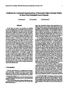
In order to judge the system’s effectiveness it is necessary to conduct a case study. In this case, the aim of the study was to generate a process plan for a machined part. A pre-requisite for this part was that it should contain a fair combination and permutation of standard features representing a process plan of average complexity. The part considered hare is a stepped bolt shown in figure 6. The constituent features of the part as derived from the STEP file by the STEP reader are shown in figure 7. It may be seen from figure 7 that the features are not arranged in any hierarchy. The stepped bolt as a machined part also permits dimensional variations. These dimensional variations may not only result in a stepped bolt of different dimensions, but also imply different manufacturing operations. Similar stepped bolts of different dimensions can easily be grouped into families. Rough turn bolt head face Rough turn OD (Major)
Cylindrical Base Shape Outer Round
Finish turn bold head face
Outer Round Revolved Profile Thread
Rough turn ODs
Turned Knurl Chamfer
Finish turn ODs
Chamfer Chamfer
Machine groove
Machine thread chamfer
Machine thread
Machine knurl
Machine chamfer
Part Off
Figure 7: Stepped bolt – Planning flowchart and constituent features The logic for generating the process plan of the stepped bolt has been developed by collecting as much information as possible from the machine shop process planners. This component represents a typical high volume production component where the conventional planning activity is well developed in the industry. Since the stepped bolt is a relatively simple part, its process plan is sequential process shown in figure 7. The planning flowchart in figure 7 represents a generative process plan. It can be seen from the flowchart that each step in the plan is based on one constituent feature of the component. The planning logic has been developed by associating each feature with a set of machining operations required to realise the feature. The feature parameters or attributes are used as input for deciding the parameters of the machining operations like the cutting speed and feed. Figure 8 shows the constituent features of the case study component. It also shows the machining operations, which are necessary to realise each feature. The resource database for this 11
case study has been developed by gathering as much data about the machines as possible. This resource data includes information about the shape, dimensions, specifications and cost of raw material stock. The database also has data about the available inserts, jig, fixtures and tools. The Serial 1 2 3 4 5 6 7 8 9
FEATURE Remark/ Information/ Operation Cylindrical Base Basic shape and size of raw material Shape Rough/ Finish turn and face Outer Round Rough/Finish turn Outer Round Rough/ Finish turn Revolved Profile Plunge Groove Thread Metric thread Turned Knurl Knurl Chamfer 45 degree chamfer Chamfer 45 degree chamfer Chamfer 45 degree chamfer Figure 8: Constituent features and operation information
machine database contains specifications of the available machines like rated power, maximum size of job, maximum cutting and feed speeds. This is used for deciding the optimum cutting and machining parameters based on the material specifications.
PROCESS PLAN Part No: Step_Bolt Description: SCREW, KNURLED Store Number: XXX-XXX-XXX OpNo 10 Collate Docs 20 Material Order 30 Kitting 40 Sawing 50 Turning 60 Inspection 70 QA Clear 80 Store 90 Dispatch 100 Clear Order
Customer: Cranfield Uni. Planner: Rohit Sharma Date: 28 October 2000 Description
Material: Material: Aluminium Drawing No.: XXX-XXX Machine ME010 ME027 ME024 107165 13137 MC130 ME016 MF031 MF033 CLOME
Figure 9: Output process plan
The resultant process plan document is shown in figure 9. The system is capable of generating up to 10 user-defined documents. The manufacturing process plan being discussed here (and shown in figure 9) is just one of the output documents. The top part of the table shows the plan header. This contains miscellaneous information such as part name, description and part number. Some of this information like part name is derived directly from the AP224 definition. Other information required for the plan header is entered by the user. Figure 9 also shows the sequence of operations required to manufacture the part. Each operation has an operation number. Operation numbers are incremented in steps of 10. This is to allow additional operations to be inserted, if required, by directly editing the output plan database. The machining centre for each operation is decided by the system depending on the selection logic entered. In the case of the stepped bolt, the system selects the machining centre based on the material and the batch size of the job. The most important 12
operation in manufacturing the stepped bolt is the turning operation, which is highlighted as operation 50 in figure 9. The details of the turning operation are shown in figure 10. This table is the detailed manufacturing turning operation instructions. Operation No: 50 Machine 13137 Serial 1 2 3 4 5 6 7 8 9 10 11 12 13 14
Description : Turning Department:
Operating Instruction Rough face 30.00mm dia down to 0mm dia removing 0.50mm from face Rough turn the 30.00mm dia. to 25.25mm dia. by length 69.50mm Finish face 25.25mm down to 0mm dia Rough turn the 25.25mm dia. to 18.25mm dia. by length 51.00mm Rough turn the 18.25mm dia. to 14.25mm dia. by length 21.00mm Finish turn the 25.00mm dia. by length 18.00mm Finish turn the 18.00mm dia. by length 30.00mm Finish turn the 14.00mm dia. by length 21.00mm Plunge Internal Groove. dia. 18.00mm with width 3.40mm Depth of groove is 3.50mm Machine the 45 degree chamfer by 1.38mm deep on the 14.00mm diameter Machine 14.00mm dia External thread by length 17.60mm with a thread pitch of 2.00mm Thread form is M Knurl 25.00mm Dia by 15.00mm long Machine the 45 degree chamfer by 1.00mm deep on the 25.00mm diameter Part off 66.00mm long
Speed 1200
Feed 0.45 mm/rev
Cut 1
1200 1200 1200 1200 1200 1200 1200 1200
0.45 mm/rev 0.25 mm/rev 0.45 mm/rev 0.45 mm/rev 0.25 mm/rev 0.25 mm/rev 0.25 mm/rev 0.01 mm/rev
1 1 1 1 1 1 1 1
1200
0.10 mm/rev
2
1136
2.00 mm/rev
1
318 1200
0.38 mm/rev 0.10 mm/rev
12 1
1200
0.12 mm/rev
1
Figure 10: Process plan – Details for turning operation number 50 Depending upon the material specifications and the feature to be manufactured, the system decides on a manufacturing process. The material specifications and the feature attributes are available from the AP224 definition. For each combination of feature to be machined, material and machine, the system has a look-up table, which is in the resource database. This table gives the cutting parameters like speed and feed. The table also gives the macro (detailed instructions) for that feature. In the next step, the system retrieves the macro commands and passes the required variables to it. Take rough facing as example, the attribute of the feature – ‘face’ and the amount of material removed and the time taken are the variables. The value of material removed is calculated from the depth-of-cut given in the resource table. The machining time is calculated from the number of cuts required to remove the required material. Then macro references a Text string and passes the variables to this Text string. These strings are actually what appear in the output as text. The text strings can be selectively directed to different documents. For example, machining instructions can be directed to the process plan and time sheet documents. The SMPS system also interfaces with the GraphCAM ® NC package for simulation and generation of NC code. This NC package is driven by a physical text file which is also generated as a standard system document. This file contains standard GraphCAM commands. The parameters of the features to be manufactured are used to generate the NC commands to machine that feature. 4.1
Support for early design
To demonstrate the use of FME in early design stage (of the same case study component), the constituent features of AP224 step library are represented in the FME library. A standard template 13
for the bolt family is created using this library. All the features have the attributes required for input to the planning system. The user needs to provide suitable values to these attributes. Some of the attributes can be automatically derived from CLIPS rules in case they have been left out. For example, the diameter of the bolt is usually related to the length of the bolt (although this is a thumb rule) and the thread parameters are dependent on the diameter. Therefore, if the user enters the length of the bolt and leaves the diameter and thread parameters out, the system can generate these parameters from the CLIPS rules (if entered). More details of using the system for early design can be found in [34]. 5
CONCLUSIONS AND FURTHER WORK
SMPS is based on sequential flowchart-type logic. In extensive user trials of the SMPS system, this has not been found to be a shortcoming and most manufacturing and process planning logic was easily mapped on to a flowchart. However, the technique described here is not limited to sequential logic. The user can embed commands within the flowchart to call an external non-conventional logic solving system like an expert system. This technique of combining the CLIPS expert system with sequential logic processing shell has also been successfully demonstrated in a previously related research work [35]. AP224 physical files are not editable directly and in most cases the only way to edit them is to edit the solid model and regenerate the AP224 definition by translation. Integration with the Feature Model Editor allows the user some flexibility in this by generating model files, which can be used as alternate input to the system in the early design stage. This is to overcome the problem of generating and editing AP224 physical files. It is envisaged that this will allow the designers to evaluate their early designs with respect to the available manufacturing processes and resources. It also provides quick evaluation of “what-if” scenarios by relocating a feature, changing its parameters or excluding it from the analysis logic. Initial case studies reveal that the system is a highly desirable conceptual design and editing aid. But the file generated by FME is for purpose of analysis only and cannot be imported into a CAD system for detailed design. Work is presently on to allow construction of a solid model from the FME part file which can then be imported into the CAD system. This will provide seamless support for progressive design, which is the end aim of this project. It is also proposed to increase the range of documents generated by the system to include production scheduling documents. ACKNOWLEDGEMENT The authors gratefully acknowledge the support of LSC Group, UK Ltd. during this research, especially Mr Alan Crawford and Mr Ray Muldoon, without whose support this would not have been possible. REFERENCES 1
2
3
Chen, Y.-M. and Yun -Tau Hsiao A collaborative data management framework for concurrent product and process development. International Journal of Computer Integrated Manufacturing, 1997, 10 (6), 446-469 Alego, M.E.A., Feng, S.C. and Ray, S.R. A state-of-the-art survey on product design and process planning integration mechanisms. Technical report No. NISTIR 5584, 1994 (National Institute of Standards and Technology, USA) Mantyla, M., Dana S. Nau and Jami J. Shah Challenges in feature-based manufacturing research. CACM, 1996, 39 (2) 85-103
14
4
5 6 7 8 9
10
11 12 13
14
15 16 17 18
19
20 21
22
23
Gindy, N.N.Z., Y. Yue and C. F. Zhu Automated feature validation for creating/ editing feature-based component data models. International Journal of Production Research, 1998, 36 (9), 2479-2495 Case, K. and J. X. Gao Feature Technology: An overview. International Journal of Computer Integrated Manufacturing, 1993, 6 (1-2) , 2-12 Yeol Lee, J. and Kwangsoo Kim A feature-based approach to extracting machining features. Computer-Aided Design, 1998, 30 (13), 1019-1035 Tseng, Y.-J. A modular modeling approach by integrating feature recognition and featurebased design. Computers in Industry, 1999, 39 (2), 113-125 Li, W.D., S. K. Ong and Nee A.Y. C. Recognising manufacturing features from a design-byfeature model. Computer-Aided Design, In Press, Uncorrected (Accepted) Industrial automation systems and integration -- Product data representation and exchange -Part 1: Overview and principles, ISO 10303, 1999, (International Organisation for Standardisation, Geneva, Switzerland). Industrial Automation Systems and Integration - Product data representation and exchange -Part 11: Description methods: The EXPRESS language reference manual, ISO 10303, 1994, (International Organisation for Standardisation, Geneva, Switzerland). Kramer, T.R., Morris, K.C. and Sauder, D.A. A structural EXPRESS editor. Technical report No. NISTIR 4903, 1992 (National Institute of Standards and Technology, USA) . Fowler, J. STEP for Data Management, Exchange and Sharing, 1995 (Technology Appraisals, London, United Kingdom). Pratt, M.J. Introduction to ISO 10303 - The STEP Standard for Product Data Exchange. (Technical note). Journal of Computing and Information Science in Engineering, 2001, 1 (1), 1-4 Industrial automation systems and integration -- Product data representation and exchange -Part 224: Application protocol: Mechanical product definition for process planning using machining features, ISO 10303, 2001, (International Organisation for Standardisation, Geneva, Switzerland). The UK Navy Mechanical RAMP Project. Project report, 1999 (LSC Group, United Kingdom). Pro Engineer User Guide, 1995 (Parametric Technology Corporation, PTC, USA) Gu, P. and Kam Chan Product modelling using STEP. Computer-Aided Design, 1995, 27 (3), 163-179 An, D., H. R. Leep, H. R. Parsaei and A. P. Nyaluke A Product Data Exchange Integration Structure Using PDES/STEP for Automated Manufacturing Applications. Computers & Industrial Engineering, 1995, 29 (1-4), 711-715 Jardim-Goncalves, R., H. Silva, M. Vital, P. Sousa, A. Seiger-Garcao and J. PamiesTeixeira Implementation of computer integrated manufacturing systems using SIP: CIM case studies using a STEP approach. International Journal of Computer Integrated Manufacturing, 1997, 10 (1-4) , 172-180 Usher, J.M. A STEP-Based Object-Oriented Product Model for Process Planning. Computers & Industrial Engineering, 1996, 31 (1-2), 185-188 Shin, Y. and Han, S.H. Integration of heterogeneous CAD database using STEP and the Internet. In International Conference on Electronic Commerce ‘98, Seoul, South Korea, April 6-10, 1998, Conference Proceedings, pp 200-205 Shaharoun, A.M., J. Ab Razak and M. R. Alam A STEP-based geometrical representation as part of product data model of a plastics part. Journal of Materials Processing Technology, 1998, 76 (1-3), 115-119 Dunbing, T., Zheng Li, Zhizhong Li and Chin Kwai-Sang STEP-based product modeling for concurrent stamped part and die development. Computers in Industry, 2001, 46 (1), 75-94
15
24
25 26 27 28 29 30 31
32 33
34 35
Bhandarkar, M.P., Blair Downie, Martin Hardwick and Rakesh Nagi Migrating from IGES to STEP: one to one translation of IGES drawing to STEP drafting data. Computers in Industry, 2000, 41 (3), 261-277 Bhandarkar, M.P. and Rakesh Nagi STEP-based feature extraction from STEP geometry for Agile Manufacturing. Computers in Industry, 2000, 41 (1), 3-24 Mannisto, T., Hannu Peltonen, Asko Martio and Reijo Sulonen Modelling generic product structures in STEP. Computer-Aided Design, 1998, 30 (14), 1111-1118 Zhang, Y., Chun Zhang and H. P. Wang An Internet based STEP data exchange framework for virtual enterprises. Computers in Industry, 2000, 41 (1), 51-63 ST-Developer Tools Reference, 2000 (StepTools, USA). Giarratano, J.C. CLIPS User's Guide, 2000 (NASA, USA). Rogerson, D. Inside COM, 1995 (Microsoft Press, USA ) Sharma, R., J. X. Gao and William Bowland A technology-driven architecture for developing highly configurable CAx software. Proceedings of the Inttitute of Mechanical Engineers, Part B, Journal of Engineering Manufacture, 2001, 215, 277-281 Young, M. XML Step by Step, 2000 (Microsoft Press, USA). Sharma, R. and Gao, J.X. A Feature Model Editor for Process Planning of Sheet Metal Products. In Proceedings of the 15th International Conference on Computer-Aided Production Planning (CAPE ’99), Durham, UK, 19-21 April 1999, Conference Proceedings, 187-194 Sharma, R. and J. X. Gao A Progressive design and manufacturing evaluation system incorporating AP224. Computers in Industry, 2002, 47 (2), 155-167 Bowland, W. and Gao, J.X. Embedded knowledge-based functionality for process planning software. In 2nd International Workshop in Intelligent Manufacturing Systems, Leuven, Belgium, 22-24 September 1999, Conference Proceedings, 497-504
16