oratory, School of Engineering Science, Simon Fraser University, Burnaby, BC. V5A1S6 Canada. .... The high-valued central plateau corresponds to ..... Dr. Gruver was a recipient of the Alexander von Humboldt U.S. Senior Scien- tist Award.
IEEE TRANSACTIONS ON SYSTEMS, MAN, AND CYBERNETICS—PART C: APPLICATIONS AND REVIEWS, VOL. 30, NO. 4, NOVEMBER 2000
517
Implementation of Vision-Based Planar Grasp Planning Kevin Stanley, Student Member, IEEE, Q. M. Jonathan Wu, Member, IEEE, and William A. Gruver, Fellow, IEEE
Abstract—This research describes the implementation of a vision-based algorithm that is capable of rapidly determining robotic grasp points for planar objects. A representation of the target and a quadtree expansion generate candidate grasps that are compared using a cost function. The approach returns the first acceptable grasp point at a given tree resolution. The system has an execution time on the order of seconds and it is suitable for a large number of planar or near planar objects. Index Terms—Grasp planning, image-based cost function, quad tree.
I. INTRODUCTION
V
ISION-BASED grasp planning is desirable for robots operating in uncontrolled environments such as service tasks, space exploration and flexible manufacturing. The ability to plan grasps for observed parts in order to manipulate them is especially important in uncontrolled environments. Nguyen [1] presented a basic framework of grasp planning for polygonal shapes. Mason [2] analyzed the mechanics of pushing, characterizing the reactions of parts to manipulation. Ponce et al. [3] expanded Nguyen’s results to general two-dimensional (2-D) shapes, and Montana [4] gave explicit definitions of contact stability. Canny and Ferrari [5] and Mirtich [6] described optimal model-based grasp planning algorithms. Nguyen and Stephanou [7], [8] characterized grasping in terms of topological subspaces and hand pre-shaping. Stephanou and Sridharan [9] extended their previous work using fuzzy proximity metrics to describe the position of the fingers with respect to the target. Guo and Gruver [10] introduced grasp stability, contact positions, and fingertip force as constraints for three–dimensional (3-D) grasp planning with multidegree of freedom dexterous hands. Borst, et al. [11] created a fast model-based grasp planner for an anthropomorphic hand. Further work has been done by Rimon and Burdik on stability bounds for frictionless contact [12]. For a recent survey of robot grasping see Bicchi and Kumar [13]. Vision-based grasp planning, which has received less attention, dynamically determines the grasp of an unknown object based on vision input. Vision-based grasp planning can be used with visual serving for vision-guided part manipulation. Vision-based grasping previously utilized part recognition and grasp selection from a set of known models [14]. Bard et al. [15] proposed a grasp planning system using Manuscript received January 1, 2000; revised November 1, 2000. K. Stanley and Q. M. J. Wu are with the Vision and Sensing Group, National Research Council—Innovation Centre, Vancouver, BC V6T 1W5 Canada. W. A. Gruver is with Intelligent Robotics and Manufacturing Systems Laboratory, School of Engineering Science, Simon Fraser University, Burnaby, BC V5A1S6 Canada. Publisher Item Identifier S 1094-6977(00)11508-1.
a voxel representation of the target. Their implementation involved a heavy computational load because of the large number of voxels required for accurate representation of the target. They used an octree data representation to reduce the complexity of the system. Janabi-Sharifi and Wilson [16] presented a feature-based grasp planner and manipulation system that relied on global features to determine a grasp. Davidson and Blake [17], and Taylor et al. [18] described a grasp planning system using B-spline interpolation of input images. Sanz et al. [19], [20] described a planner employing symmetry information to determine suitable grasp points. Unlike other image-based planners, however, the latter research does not require a geometric reconstruction of the image. This paper presents a vision based planar grasp planner in the spirit of Sanz et al. [19], [20]. The proposed grasp planner is local and image based, employing a cost function to determine grasp quality. There are several key differences, however, between our planner and previous research. First, we use a representation of the target allowing cost function evaluation with a set of lookups. Second, we use a progressive sampling technique similar to quadtree expansion to generate potential grasp points. Finally, we use feature calculations in a cost function. The result is a general, efficient, 2-D grasp planner. Our method achieves grasp planning within fractions of a second to less than eight seconds depending on the complexity of the object. Like the Sanz planner, our approach has some significant advantages and disadvantages when compared to the more traditional geometric approach [1]–[13]. Pixel-based grasp planners allow planning directly on the image without a costly curve fitting step. This approach also allows us to employ tools from computational robotics, such as the quadtree expansion, which would be unavailable in a strictly geometric algorithm. However, we sacrifice the guaranteed stability and computational complexity of geometric techniques. A pixel-based grasp planner is faster and more flexible, but less mathematically rigorous than a geometric approach. To reduce the number of calculations, we assume that objects will have several suitable grasp points. This assumption seems to hold in practice because nondegenerate objects are common in industrial assembly and machining. The proposed algorithm evaluates points on the boundary of the object, and progressively refines the search until a grasp is found. The grasp planner finds feasible grasp points that are collision free and stable. The algorithm evaluates all grasp points at a given level of resolution, and returns a grasp point that satisfies the requirements and has minimum cost at the given level of the tree. Although the grasp points may not be globally optimal, the points are better than others.
1094–6977/00$10.00 © 2000 IEEE
518
IEEE TRANSACTIONS ON SYSTEMS, MAN, AND CYBERNETICS—PART C: APPLICATIONS AND REVIEWS, VOL. 30, NO. 4, NOVEMBER 2000
Fig. 1.
Example of object expansion and features.
Fig. 2.
Output of the vision system for grasp planning.
A. Assumptions This research is based on the following assumptions: 1) there is good intensity contrast between the target and the background; 2) parallel grippers only grasp normal to the object surface; 3) targets have a planar or near planar top surface; 4) grasp points exist on the object; 5) the target is completely visible (no occlusion or clipping). Assumption 1 allows us to use simple segmentation algorithms and concentrate on the grasp-planning problem. Assumption 2 limits the search to two degrees of freedom. Assumption 3 allows us to only consider the exterior boundary, and ignore possible height contours that may cause a collision. Assumption 4 allows us to treat all objects as graspable. Assumption 5 implies that the visible target contains all boundary information. II. ALGORITHM DESCRIPTION The proposed algorithm is based on a quadtree resolution expansion of the image. At each level, pixels corresponding to the and midpoints of the current quadtree windows are examined for satisfactory grasp points. If no suitable grasp points are found, the cells of the quadtree are divided, and the procedure is repeated. Because a breadth first search is used, the algorithm has more in common with sampling than searching. To determine the suitability of a grasp point, a fitness function is used. The fitness function is a linear combination of features that represent the quality of the current grasp. The behavior of the system is tied closely to the fitness function, which encodes what is considered a good grasp point and what is considered a poor grasp point. Fig. 1 illustrates the various components of
the grasp planner, including the quadtree expansion, the fitness function features and the definition of a normal. The dotted rectangles in Fig. 1 show the quadtree decomposition of the image. At each resolution level the midpoints of the and -axis of the window are sampled. Cells not containing edge elements are discarded. The dashed lines above and to the left of show midpoint sampling. The letter pairs illustrate potential grasp points for analysis. A. Boundary Isolation A grasp planning algorithm requires a representation of the target’s boundary. Most grasp planning algorithms use computationally intensive, geometric representations of the boundary to generate image data. To reduce computation, we have used a pixel-based grasp planner with an efficient representation of the boundary. The background is represented as black pixels (value 0), the interior is represented by white pixels (value 255), and the boundary is represented by the gradient orientation that is analogous to the surface normal for planar targets. The gradient orientation is represented as an angle from 0 to , discretized on the grayscale interval 1 to 254. The result is a black and white image surrounded by a grayscale shell as shown in the “Final Image” of Fig. 2. This representation allows the grasp-planning algorithm to identify easily the edge, interior and exterior, and the surface normal using only lookup operations. We use a standard hole elimination procedure to ensure that the grasp planner only generates external grasps. B. Quadtree Expansion The algorithm expands the current node into four nodes a) quadtree expansion) then stores only those nodes that contain
STANLEY et al.: IMPLEMENTATION OF VISION-BASED PLANAR GRASP PLANNING
part of the boundary. Mixed nodes are easily identified from the gray level histogram because they have multiple grayscale occupancies. The histogram is reused during the calculation of the curvature feature. The result of the expansion algorithm is a list of nodes containing boundary pixels, which can be analyzed using the fitness function to find suitable grasp points. C. Fitness Function The fitness cost function determines the behavior of the system. The fitness function is represented by
519
Distance to Center of Mass: The distance to the center of mass feature is calculated as the perpendicular distance from the center of area of the object to the line connecting the two grasp points. It measures the stability of the grasp with respect to rolling about the grasp axis. If the grasp is off center, the object may torque under the influence of gravity exerted at the center of mass. The center of mass is included to provide some context differentiating grasps along parallel surfaces such as the edges of a cube. D. Opposite Point Location
(1) where standard deviation of the grayscale histogram; difference between surface normals of two grasp points; distance from the grasp axis to the center of mass; , , and positive scalar parameters. The relative weightings of the different features determine the local sensitivity. The weightings were determined heuristically and experimentally. The fitness function is a linear sum of the three features, but the surface of the fitness function is nonlinear because both the curvature and distance to center of area are nonlinear functions. The global sensitivity of the fitness function is uniform because there is no change in the derivative of the fitness function as the magnitude of the individual features change. The fitness function is bounded above and below. The lower bound is zero because the fitness function is a sum of strictly positive features. The upper bound is set by the user and determines the level of acceptability. The constants are scaled such that a fitness value of unity should generate a marginally stable grasp. Good result were obtained with the upper bound set at 0.7. Curvature: The standard deviation of the surface normal along the boundary segment in the image was chosen as a measure of curvature. This measure of curvature is independent of the size of the current window consistent for similar curves, is independent of the curve’s position, and quickly calculated given the grayscale histogram of the boundary orientation. A line segment is represented by a single spike in the histogram of the gradient orientation. A circle is a constant distribution across all grayscale levels. A number of line segments yields a multimodal distribution. Parallelism: The parallelism feature determines the grasp stability. Parallelism is measured as the difference between the surface normals of the opposing grasp points. The stability of the grasp is determined by the difference in orientation between the two surface normals, because we assume that the grippers are parallel. In addition, because we have assumed parallel jaw grippers, the most stable condition occurs when the opposing grasp points are on parallel faces of the target. The absolute value of the difference between the surface normals at the grasp points therefore gives us a measure of the stability of the grasp. The measure is minimum at zero, and approaches as the angle between grasp points becomes perpendicular.
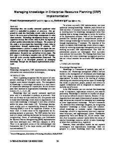
In order to reduce the amount of bookkeeping and memory required to store all nodes in the graph, the search for the opposite point is performed directly on the image, not on the windows or nodes. Since we assume the second grasp point lies along the line normal to the surface at the first grasp point, the two-dimensional search can be reduced to a single dimension. An example of the information along this line is in Fig. 3. Fig. 3 represents a linear cross section of a convex object along the dashed line. The vertical axis represents the intensity of the pixels along the lines, and the horizontal axis refers to the distance along the line. The zero valued section at either end corresponds to the black background. The high-valued central plateau corresponds to the interior of the object and the two smaller shelves correspond to the edges of the objects. Because the system only has four values, interior, exterior and both edges, steepest decent searches are impossible. Examining the data set closely reveals that in fact there are only two values, inside (max) and outside (min), a classic binary search problem. A binary search is employed starting at the first grasp point and the opposite corner of the image and terminating when the opposite side has been found. The opposite point location algorithm also performs a validity check on the selected grasp point. For this implementation, only exterior grasp points are considered (holes are eliminated during the image processing step). Therefore, it is necessary to ensure that the boundary found is an opposing boundary for concave objects The far-left point in Fig. 4 is the start of the search. The other two points are potential solutions of the binary search. The far right point fails because the adjacent area along the line is background. The second point is valid because the area between it and the original point is inside the target. III. COLLISION DETECTION The collision detection algorithm is also image based. The gripper is represented by a rectangular projection. The gripper is rotated so that it is parallel with the current grasp point, then moved so that the center of the leading edge of the gripper would touch the candidate point. A window, the same dimensions as the gripper window centered at the candidate grasp point, is extracted from the original image. The result of the image and the gripper model are intersected. A diagram of this operation is shown in Fig. 5. Any internal regions occupying the same space as the gripper remain white, whereas all other regions are black. The histogram of the result is calculated. If the number of interior
520
IEEE TRANSACTIONS ON SYSTEMS, MAN, AND CYBERNETICS—PART C: APPLICATIONS AND REVIEWS, VOL. 30, NO. 4, NOVEMBER 2000
Fig. 3. Representation of the linear search.
Fig. 6. Fig. 4. Valid and invalid opposing grasp points.
Fig. 5.
Collision detection steps.
cells is larger than a small threshold, a collision has occurred. Ideally, a collision should occur when a single white pixel is found, but quantization errors in the angle allow small numbers of interior pixels to intersect with the gripper. The assumption that grasping only occurs at the center of the finger eliminates potentially stable and valid grasp configurations. However, searching for additional grasp points off-center adds an additional dimension to the search, increasing the computational complexity. For cases that fit our initial assumption of many suitable grasp points, this action is unnecessary. For grasping highly concave objects with few grasp points, the additional complexity may be required.
Experimental results for a square object.
IV. COMPUTATIONAL COMPLEXITY It is difficult to estimate the computational complexity of a system that employs early stopping to reduce computation. There are two aspects to examine: how much it costs to calculate the fitness function at each node, and how much it costs to perform the quadtree expansion. Three major steps follow the expansion of the previous layer: determine which nodes contain boundary nodes; determine the features for each node; and evaluate where winning nodes generate collisions. First, we must determine if the current node contains boundary elements. The complexity at level is given by (2) is the number of nodes or windows in the current layer where is the number of pixels in each window in the current and layer. The complexity for each feature calculation and the binary search for the opposite edge follow. The complexity of the curvature calculation is (3) is the grayscale resolution of the histogram, usually where are reserved for rep256. The upper and lower bounds of resenting the interior and exterior of the target, and therefore
STANLEY et al.: IMPLEMENTATION OF VISION-BASED PLANAR GRASP PLANNING
521
Fig. 7. Experimental results for a circular object.
are not examined. The complexity of the distance from center of mass, and relative orientation calculations are small numbers and . The complexity of the binary search for the opposite grasp point is given by (4) where is the maximum length of the line separating the points and is the width of the edge. Ignoring early stopping for feature evaluation, the total cost is (5) Fig. 8.
Experimental results for a brace.
(6) Finally, if the node has the smallest cost, the node must be checked for collisions. The cost of collision detection is given by (7) is the size of the gripper window. Therefore the total where cost for the calculation of node in level is given by (8) is the number of boundary nodes on level and where is the number of winner nodes on level . From (2)–(8) the node evaluation computational complexity is linear. Since the grasp planner must execute a node calculation for every node in the tree, it should increase as (9) where is the number of levels in the current tree. However, because and the growth of the system is much slower. By pruning irrelevant nodes from the tree, the computational cost is closer to order 2 calculation than an exponential calculation, as shown in our results. V. RESULTS To demonstrate the capabilities of the grasp planning system, we evaluate performance for both synthetic and real images. The algorithm was tested on several classes of shapes to determine
its ability to correctly and efficiently determine acceptable grasp points for all types of objects. A. Straight Convex Objects Objects with straight sides and convex profiles are common in industry. This set includes convex polygons. Not only do we want the grasp planner to find acceptable grasp points for simple shapes, we want the grasp planner to find good grasp points. In this case the distance metric must distinguish between points on the periphery of the target and grasp points whose contact line passes though the center of mass of the object. To demonstrate the behavior of the system for this case we have used a square block as shown in Fig. 6. The selected grasp points form a line passing near the center of the square. The points corrupted by noise were rejected because of the curvature constraint. The points that satisfy the quality constraint were replaced by one closer to the center of mass. The point was off-center because no valid points closer to the center were examined. Fig. 6 clearly demonstrates the tradeoffs associated with early stopping: a suboptimal but valid result is found very quickly, even though a better grasp point would likely have been found on the next quadtree expansion. B. Curved Convex Objects The class of curved convex objects includes completely curved objects such as ellipses as well as mixed curved and straight objects commonly found in industry. The algorithm behaves in a similar fashion for curved convex objects as it does with straight convex objects. The algorithm selects good grasp points over acceptable grasp points based on the position
522
IEEE TRANSACTIONS ON SYSTEMS, MAN, AND CYBERNETICS—PART C: APPLICATIONS AND REVIEWS, VOL. 30, NO. 4, NOVEMBER 2000
Fig. 9. Experimental results for a complex polygonal object.
Fig. 10.
Experimental results for arbitrary shaped object.
of grasp points relative to the center of mass. To illustrate the behavior of the algorithm for curved convex objects, we used a circular sleeve. The grasp planner selected to be a radial rather than a cord grasp point pair, rejecting nonradial grasp points on the basis of curvature and distance from the center of mass, as shown in Fig. 7. C. Straight Concave Objects The class of straight edged concave objects includes all the nonconvex polygons. Nonconvex polygons are commonly found in flanges, braces and other assembly pieces. The requirements for grasp planning for nonconvex polygons are similar to the requirements for convex polygons. The grasp point must be stable, near the center of mass, and collision free. The result demonstrates a compromise between the distance from the center of mass and the size of the target. The grasp points along the longer axis of the bracket were rejected because the bracket’s length is longer than the distance between the gripper fingers, as shown in Fig. 8. To further verify our results for this more complex target, and to demonstrate our collision checking capabilities, we ran the grasp planner on a complex shape generated graphically. The results are shown in Fig. 9. As is apparent from this example, many more samples were required to generate an acceptable grasp point. D. Curved Concave Objects The class of curved concave objects includes all curved nonconvex objects and all objects with mixed straight and curved
sides with concavities. This is the most general and complex set. We expect the class of curved concave objects to require more iterations because the number of potential grasp points is small. The number of invalid grasp points due to grasp length and collisions are also expected to be much higher than the previous cases. To demonstrate the behavior of the system with respect to curved concave objects we used the arbitrary shape shown in Fig. 10. In this case, the algorithm returned a solution much faster than we anticipated, requiring only two levels of expansion (32 windows) to generate an acceptable grasp. The grasp in Fig. 9 satisfies the collision, parallel, and curvature constraints, and it occurs at a significant distance from the center of mass, demonvalue and coefficient are properly tuned. strating that the The selected point is far from the center of mass because the other grasps generated collisions or did not satisfy parallelism requirements. To demonstrate the limits of this algorithm, we have tested the grasp planner on a synthetic target generated graphically. Many ellipses were merged to create a curved object with only locally continuous boundary segments, as shown in Fig. 11. Again, the grasp planner required many more points to find a solution, but a solution was found. E. Processing Time We have developed an algorithm that requires computation that is commensurate with the complexity of the target. To measure the actual behavior of the system, a timer was added to the main program loop. At the end of each grasp point determination, the required level of expansion and the elapsed time were recorded. Theoretically, the algorithm should be exponential with the level of expansion, however, we observed a much
STANLEY et al.: IMPLEMENTATION OF VISION-BASED PLANAR GRASP PLANNING
Fig. 11.
Experimental results for a complex object.
Fig. 12.
Execution times.
slower rate of growth. Processing time versus level of expansion is shown in Fig. 12. The topcurvedenotestheidealexponentialgrowth.Thebottom curve represents the measured response. The measured results are approximated by a polynomial curve of degree 2. The difference in computation time becomes significant at the fourth level of expansion. This effect was primarily due to discarding nonedge nodes and early stopping on analysis of unpromising grasp points. Table I shows the average time for each level of expansion and the number of points examined in that level. VI. CONCLUSIONS The major contributions of this paper are an efficient image representation and a fast algorithm for image-based grasping. We have developed an image-based algorithm capable of planning grasps for a wide range of planar objects. The grasp planning system uses an approximate decomposition method to determine useable grasp points for objects of various shapes. The system is designed to find feasible grasp points using a quadtree decomposition of the object boundary to systemati-
523
TABLE I AVERAGE EXECUTION TIMES PER LEVEL OF EXPANSION
cally sample the boundary for candidate grasp points. The input for the quadtree analysis is a grayscale image of the object with an explicit representation of the interior exterior and surface normals around the object. The evaluation of the grasp quality is performed using a cost function composed of a weighted sum of the difference in normals, curvature, and distance from the center of area. Potential grasps are checked for physical validity using a collision checker and a model of the maximum grip length of the end-effector. We have demonstrated successful grasp planning for a variety of different target shapes. We have shown that grasps can be planned in seconds.
524
IEEE TRANSACTIONS ON SYSTEMS, MAN, AND CYBERNETICS—PART C: APPLICATIONS AND REVIEWS, VOL. 30, NO. 4, NOVEMBER 2000
REFERENCES [1] V. D. Nguyen, “Constructing stable grasps,” Inte. J. Robot. Res., vol. 8, pp. 3–16, Feb. 1989. [2] M. T. Mason, “Mechanics and planning of manipulator pushing operations,” Int. J. Robot. Res., vol. 5, no. 3, 1986. [3] J. Ponce, D. Stam, and B. Faverjon, “On computing two-finger forceclosure grasps of curved 2D objects,” Int. J. Robot. Res., vol. 12, no. 3, pp. 263–273, June 1993. [4] D. J. Montana, “Contact stability for two-fingered grasps,” IEEE Trans. Robot. Automat., vol. 8, pp. 421–430, Aug. 1992. [5] C. Ferrari and J. Canny, “Planning optimal grasps,” in IEEE Conf. Robotics Automation, May 1992, pp. 2290–2295. [6] B. Mirtich and J. Canny, “Easily computable optimum grasps in 2-D and 3-D,” in IEEE Conf. Robotics Automation, May 1994, pp. 739–747. [7] T. N. Nguyen and H. E. Stephanou, “A topological algorithm for continuous grasp planning,” in IEEE Int. Conf. Robotics Automation, vol. 1, May 1990, pp. 13–18. [8] T. N. Nguyen and H. E. Stephanou, “A continuous model of robot hand preshaping,” in IEEE Int. Conf. Systems, Man, Cybernetics, 1989, pp. 798–803. [9] K. Sridharan and H. E. Stephanou, “Fuzzy proximity measures for robot grasp planning,” in IEEE Int. Conf. Intelligent Control, 1992, pp. 220–224. [10] G. Guo and W. A. Gruver, “Dynamic grasp planning for multifingered H and is based on asymptotic stability,” IEEE Trans. Syst., Man, Cybern. B, vol. 26, pp. 764–768, Oct. 1996. [11] C. H. Borst, M. Fischer, and G. Hirzinger, “A fast and robust grasp planner for arbitrary 3D objects,” in IEEE Int. Conf. Robotics Automation, May 1999, pp. 1890–1896. [12] E. Rimon and J. W. Burdick, “New bounds on the number of frictionless fingers required to immobilize 2D objects,” in IEEE Int. Conf. Robotics Automation, 1995, pp. 751–757. [13] A. Bicchi and V. Kumar, “Robotic grasping and contact: A review,” in IEEE Int. Conf. Robotics Automation, Apr. 2000, pp. 348–353. [14] R. Govindan and A. S. Rao, “Optimal strategies for recognizing polygonal parts,” in IEEE Int. Conf. Robotics Automation, May 1994, pp. 3464–3569. [15] C. Bard, C. Laughier, C. Milesi-Bellier, B. Triggs, and G. Vercelli, “Achieving dexterous grasping by integrating planning and vision-based sensing,” Int. J. Robot. Res., vol. 14, pp. 445–464, Oct. 1995. [16] F. Janabi-Sharifi and W. J. Wilson, “Automatic grasp planning for visual Servo controlled robotic manipulators,” IEEE Trans. Syst., Man, Cybern. B, vol. 28, pp. 693–711, Oct. 1998. [17] C. Davidson and A. Blake, “Error tolerant planning of planar grasp,” in Proc. 6th Int. Conf. Computer Vision, 1998, pp. 911–916. [18] M. Taylor, A. Blake, and A. Cox, “Visually guided grasping in 3D,” in Proc. 1994 IEEE Int. Conf. Robotics Automation, 1994, pp. 761–766. [19] P. J. Sanz, A. P. del Pobil, and J. M. Inesta, “Curvature-symmetry fusion in planar grasping characterization from 2D images,” in Proc. Industrial Engineering Applications Artificial Intelligence Expert Systems, Amsterdam, The Netherlands, 1997, pp. 45–52. [20] P. J. Sanz, A. P. del Pobil, J. M. Inesta, and G. Recatala, “Vision guided grasping of unknown objects for service robots,” in Proc. 1998 IEEE Int. Conf. Robotics Automation, Leuven, Belgium, May 1998, pp. 3018–3025. [21] K. Stanley, Q. M. J. Wu, A. Jerbi, and W. A. Gruver, “A fast two-dimensional image based grasp planner,” in IEEE Int. Conf. Intelligent Robots Systems, Kyongju, Korea, Oct. 1999. [22] E. R. Davies, Machine Vision. New York: Academic, 1997.
Kevin G. Stanley (S’00) received the B.A.Sc. and M.A.Sc. degrees in engineering science from Simon Fraser University, Burnaby, BC, Canada in 1999, where he is currently pursuing the Ph.D. degree. He is a Technical Officer with the Vancouver Innovation Centre, National Research Council Canada, Vancouver, BC. His research interests include vision-guided robotics, grasp planning, high-resolution imaging, sensor fusion, and sensor design. Mr. Stanley is a past recipient of the GREAT Fellowship Award from the British Columbia Science Council.
Q. M. Jonathan Wu (M’92) received the Ph.D. degree in electrical engineering from the University of Wales, Swansea, U.K., in 1990. He is a Research Officer and Group Leader at the Vancouver Innovation Centre, National Research Council Canada, Vancouver, BC, Canada. He is also an Adjunct Professor with the School of Engineering Science, Simon Fraser University, Burnaby, BC, Canada. From 1982 to 1984, he was a Lecturer at Shandong University. From 1992 to 1994, he was with the University of British Columbia, Vancouver, as a Senior Research Scientist. His research interests include pattern recognition, image analysis, neural networks, robotics, intelligent control, and computer vision systems.
William A. Gruver (F’96) received the B.S.E.E., M.S.E.E., and Ph.D. in electrical engineering from the University of Pennsylvania, Philadelphia, in 1963, 1966, and 1970, respectively. He received the D.I.C. degree in automatic control systems from the Imperial College of Science and Technology, University of London, London, U.K., in 1965. He is Professor of engineering science at Simon Fraser University, Burnaby, BC, Canada. His industrial experience includes senior and technical management positions. At the General Electric (GE) Industrial Electronics Laboratory, Charlottesville, VA, he managed development of robot vision and simulation software. As Manager of the GE Automation Center in Germany, he established a major European technology center for computer integrated manufacturing. As Division President at IRT Corporation, San Diego, CA, he was responsible for a new product line for automated X-ray inspection. As Director of the Center for Robotics and Manufacturing Systems, University of Kentucky, Lexington, he established research programs specializing in manufacturing and automation, and a state-wide assistance program for manufacturing companies. As Vice President of LTI Robotic Systems, a California based startup that he co-founded, he directed R&D and consulting projects in the U.S. and Japan involving automation systems, robot controllers, and robot languages. He has also held positions at NASA’s Marshall Space Flight Center, DFVLR German Space Research Center, Technical University Darmstadt, U.S. Naval Academy, and North Carolina State University. He has published 160 technical articles and three books on robotics and manufacturing automation. His current research interests are multiagent methods for manufacturing resource management and robotic system integration, and applications of robotics and intelligent sensing in manufacturing and service tasks. He is an active member and served as an international work package leader of the Holonic Manufacturing Systems (HMS) Project, an international consortium of the IMS Program, developing and standardizing agent-based technologies for manufacturing. He is a member of the editorial board of the Journal of Robotics & Autonomous Systems, and he frequently serves on program committees of major conferences. He is General Co-Chair of the 2001 Joint 9th IFSA World Congress and 20th NAFIPS International Conference on Fuzzy Systems and Soft Computing to be held in Vancouver. Dr. Gruver was a recipient of the Alexander von Humboldt U.S. Senior Scientist Award. In 1995, he was elected an IEEE Fellow for his “leadership of major international programs in robotics and manufacturing systems engineering.” He is an Associate Editor of the IEEE TRANSACTIONS ON SYSTEMS, MAN AND CYBERNETICS and he chairs the technical subcommittee on Robotics and Manufacturing Automation of the IEEE SMC Society. He has served as an AdCom member of the IEEE SMC Society, Vice President of Publications, and Vice President of Conferences and Meetings. He was an associate editor for the IEEE TRANSACTIONS ON ROBOTICS AND AUTOMATION, associate editor of the IEEE TRANSACTIONS ON CONTROL SYSTEMS TECHNOLOGY, and a founding officer of the IEEE Robotics and Automation Council. He has served as General Chair of the 1994 IEEE International Conference on Robotics and Automation, General Chair of the 1995 IEEE International Conference on SMC, and Program Co-Chair of the 1999 IEEE International Conference on SMC.