Copyright 2001 Society of Photo-Optical Instrumentation Engineers. This paper was published in Proceedings of SPIE Vol. 4591, pp. 316– 327, 2001 (SPIE Electronics and Structures for MEMS, Adelaide, December 2001), and is made available as an electronic reprint with permission of SPIE. One print or electronic copy may be made for personal use only. Systematic or multiple reproduction, distribution to multiple locations via electronic or other means, duplication of any material in this paper for a fee or for commercial purposes, or modification of the content of the paper are prohibited.
Implementation of visual motion detection with contrast adaptation Patrick A. Shoemakera*, David C. O’Carrollb, Andrew D. Strawb a Tanner Research, Pasadena, CA; b Adelaide University, Department of Physiology & Centre for Biomedical Engineering ABSTRACT Visual detection and processing of motion in insects is thought to occur based on an elementary delay-and-correlate operation at an early stage in the visual pathway. The correlational elementary motion detector (EMD) indicates the presence of moving stimuli on the retina and is directionally sensitive, but it is a complex spatiotemporal filter and does not inherently encode important motion parameters such as velocity. However, additional processing, in combination with 'natural' visual stimuli, may allow computation of useful motion parameters. One such feature is adaptation in response to motion, until recently thought to occur by modification of the delay time constant, but now shown to arise due mainly to adjustment of contrast gain. This adaptation renders EMD output less dependent on scene contrast and enables it to carry some velocity information. We describe an ongoing effort to characterize this system in engineering terms, and to implement an analog VLSI model of it. Building blocks for a correlational EMD, and a mechanism for computing and implementing adjustment of contrast gain are described. This circuitry is intended as front-end processing for classes of higher-level visual motion computation also performed by insects, including estimation of egomotion by optical flow, and detection of moving targets. Keywords: insect vision, motion detection, adaptation, neuromorphic, analog VLSI
1. INTRODUCTION Although insects are relatively simple organisms compared to vertebrates, with nervous systems of limited size and complexity, they nonetheless do a remarkable job of controlling flight and other behaviors based on their low-resolution visual sense. Computation of optical flow for estimation of egomotion, and detection and tracking of small moving targets, are two examples of processing that occur in the insect visual system. Similar capabilities could greatly enhance the performance of artificial systems such as autonomous flying vehicles, if they could be duplicated in a man-made sensing and processing system. Because all insect motion processing appears to be based on a fundamental elementary motion detector (EMD) 1 , we expect that a robust and reasonably faithful model of such a detector is critical for further development of insectinspired, biomimetic processing. While a basic correlational model of the EMD has been well established for decades,1,2,3 other important features (in particular the capacity for motion adaptation and response invariance with respect to non-motion-related parameters) are less thoroughly understood. However, recent physiological evidence and modeling of both early visual pre-processing 4 and insect motion detectors 5,6 have clarified the nature and role of adaptive processes in early motion processing. These advances suggest that we are very close to a practically useful model of early motion processing in insects.
*
[email protected]; phone 1 626 792-3000; Tanner Research, Inc., 2650 East Foothill Blvd., Pasadena, CA 91107, USA
The small scale (a few thousands of pixels) and relative simplicity of the arthropod visual system suggest that it may be possible to implement similar early processing with analog circuits using contemporary microelectronic technology. We discuss recent advances in modeling of insect motion processing, and report the initial steps of an effort to develop an analog of the adaptive EMD, while addressing some of the critical issues that have hindered the development of ‘neuromorphic’ VLSI in general.
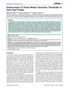
2. MOTION DETECTION AND PROCESSING IN INSECTS 2.1 Background Considerable progress has been made in the study of insect visual systems and aspects of visual processing in insects since the mid-1950s. An early and still influential model of early motion detection, the correlational elementary motion detector (EMD), was first formulated by Hassenstein and Reichardt in 1956.1 This model is based on a correlation of the response of one pixel to the delayed response of a neighboring pixel, as depicted schematically in Figure 1:
RECEPTORS
DELAYS (LOW-PASS FILTERS)
τ
τ
CORRELATORS
+
_
OUTPUT Figure 1: The correlational elementary motion detector.
The combination of the spatial connectivity, the delay time constant τ , and the nonlinear interaction of the correlator endow the EMD with a directional motion sensitivity, while the final opponent stage enhances the directional properties and rejects the effects of flicker or static luminance signals. The correlation operation is typically modeled as a multiplication. The correlational EMD model is well supported by physiological and behavioral evidence, although its anatomical substrate has been hard to pinpoint. Neuroanatomical studies and some physiological evidence have identified likely candidate neurons in the second optic ganglion or insect medulla 7 but these neurons have proved too tiny for reliable study by standard intracellular recording. Physiological data in support of the EMD model have been taken primarily from more central cells in the lobula complex (third optic ganglion), which are believed to receive and collate inputs from retinotopic arrays of EMDs.8,9 While these cells have provided invaluable preparations for study, we note that it is often not a trivial matter to make unambiguous inferences about the EMD from their behavior, due to the confounding effects of their own properties and any intervening or parallel inputs that may be present.
2.2 The role of the EMD in motion processing Although isolated EMDs do not give simple unambiguous velocity information (they are in fact complex spatiotemporal filters), theory suggests that this type of motion detector is inherently well suited to tasks that might be limited by noise.10 Such tasks include the detection and analysis of very small targets, and motion detection at low light levels or in cluttered scenes. This may explain why such motion detectors seem to be widespread in biological vision. In insects, they are thought to form the major input to higher levels of motion processing, where behaviorally relevant data begin to be computed (e.g., optical flow patterns and the detection of moving targets). For this reason, and because they have been well studied and modeled, we consider insect EMDs and conceptually similar small-field motion detectors to be prime candidates for on-focal-plane implementation. The neurons found at higher levels of insect visual systems have response characteristics that are relevant to the animals’ remarkable performance in their environments, and which would naturally be applicable to artificial autonomous systems. One class of cells has wide receptive fields and is sensitive to optical flow fields (such as divergence, rotation, etc.) that can be expected to result from egomotion. These cells are thought to play a role in navigation or guidance, as well as certain reflexive reactions (such as the landing reflex and yaw stabilization during flight on a constant bearing). In dipteran flies, the best studied set of identified ‘tangential’ neurons in the lobula plate (a specialized area of the lobula) mediate corrective responses to rotational motion, providing an ‘autopilot’ system for stabilizing flight. Twentyeight key neurons of this system have been categorized as horizontal system (HS) and vertical system (VS) cells based on their global direction sensitivity. Recent work suggests that these neurons are not simple global horizontal or vertical motion detectors, but ‘matched filters’ for specific rotational patterns The VS1 neuron, for example, has a large receptive field excited by downward motion frontally and forward motion at the top, which suggests that it is tuned for rotational motion about the pitch axis . Other VS neurons appear to provide a complete complement of pitch and roll detectors, while extensive work has demonstrated that HS cells directly control reactions to yaw.11,12 In addition, other classes of higher-level neurons have been identified in a number of species, whose responses suggest they play a role in the detection and tracking of moving targets. One such class of cells displays sensitivity primarily to front-to-back motion of moderate-sized targets, and is thought to be part of a system (called the FD system) in dipterans that mediates a turning response toward objects in the visual field that display parallax motion with respect to background 13,14 Another class displays sensitivity to very small moving targets (subtending one or two facets of the compound eye) moving with respect to background within their fields. These small target, movement detecting neurons (STMDs) were first described in the odonates (dragonflies), an order of insects that chase prey on the wing and use visual cues to estimate its course and intercept its flight path.15,16 Similar cells have now also been described from hoverflies, another highly visual and aerobatic insect that engages in high-speed pursuit behavior.17,18 The responses of STMDs are typically direction sensitive, and display a distinct spatiotemporal optimum, suggesting that they receive input from correlation-type EMDs. Models for the processing of these neurons are emerging, but are more tentative. The most recent data (O’Carroll, unpublished) suggest that their very small target selectivity derives from more complex feedforward and feedback inhibitory mechanisms than those that seem to explain size preference in the better-modeled FD1 cell of the blowfly lobula plate. While considerable evidence has accumulated to support the correlational EMD model as a basic unit of motion processing in insects, it is clear that it has some significant limitations and that additional processing is required even at the early stages of motion detection in order to eventually derive signals useful for forming motor commands. The estimation of para meters of motion (whether egomotion or target motion) from spatiotemporal patterns of visual stimuli implicitly requires responses that are invariant with respect to absolute illumination levels, contrast, and spatial structure of scenes in the visual field. However, all these parameters strongly affect the response of individual EMDs or ensembles of EMDs. A useful parameter of motion is its component of velocity along the EMD axis, but the basic EMD does not provide an unambiguous representation of this quantity. In spite of this, convincing behavioral evidence has been presented in recent years to suggest that flying insects (bees) perform visual odometry.19 This has led some researchers to postulate elaborated EMD processing schemes (i.e., systems of EMDs with multiple time constants) or even different mechanisms altogether, to explain the apparent ability of insects to judge image velocity. Some aspects of the ways that these issues are addressed in early motion processing are understood (e.g., the logarithmic and adaptive nature of photoreceptors allows response to contrast rather than absolute illumination intensity -- and these
features can be mimicked in silicon), but in many other cases they are the object of active research. In particular, recent work has shed new light on the nature of adaptation and the role it plays in the processing of motion. 2.3 Motion adaptation and its role in motion processing Adaptation in the motion processing system of the blowfly was first described in the 1980’s.20,21,22 In brief, exposure to moving imagery reduces the response of lobula plate neurons such as HS or H1 relative to the unadapted state (i.e., in the absence of prior visual motion) and leads to increased modulation of responses by different velocities of motion. In part because of the wide range of velocities expected in natural images perceived by flying insects, it has been widely assumed that the time constant in the delay leg of the EMD is a likely target for modification by the process of adaptation. Indeed, several studies of the ‘velocity impulse response’ of adapted and unadapted visual systems in both insects and vertebrates seemed to suggest that the fundamental mechanism of motion adaptation is a decrease in the time constant of the delay.20,21,22 However, recent work by Harris, O’Carroll, and colleagues sheds doubt on the ‘shortening delay theory’ of motion adaptation. They showed that a key prediction of this theory – a shift in optimal velocity following adaptation is not observed.6 Rather, the most obvious effect on velocity tuning is a decrease in overall sensitivity to moving patterns following exposure to motion.6,23 They further demonstrated that adaptation consists of two distinct phenomena: (1) a post-excitatory hyperpolarization or shifting downward of the mean membrane potential in a target cell; and (2) a reduction of the contrast gain of the system. 5 Collating all of the available evidence for motion adaptation in the dipteran visual system, we can summarize the key features as follows: 1. The ‘post-excitatory’ hyperpolarization is an activation-dependent feature of the target collator cell and thus is direction-selective. Stimuli presented in null or anti-preferred directions fail to recruit this effect. The contrast gain reduction is independent of the target cell activation, i.e., it can be elicited by stimuli moving in a direction that causes no excitation or even inhibition of the target cell. From these findings, it can be concluded that the contrast gain reduction acts prior to the target cells and that it must involve ‘omnidirectional’ signals. 2. Stimuli which have similar spatiotemporal structure to that producing the greatest activation or inhibition of the motion detector outputs, if presented in the preferred or anti-preferred orientation of EMDs, also lead to the greatest contrast gain reduction, irrespective of the presentation orientation. Adaptation is also less pronounced when nonmotion-related temporal contrast (either wide-field or local ‘flicker’) is present. This shows that the adaptation is driven by similar spatiotemporal filters to motion detection itself and implies that the contrast gain control is somehow mediated by motion (EMD outputs). 3. The contrast gain reduction component of adaptation is retinotopic and occurs on a size scale similar to that of individual EMDs. One obvious function of such a mechanism might be to maintain the processing elements (neurons) in the EMD and subsequent cells in a non-saturated state, to maximize the transfer of information through the system under a range of operating conditions. This would permit the system to operate with an inherently high gain and thus maximize the range of velocities over which a single EMD class could reliably code motion. This possibility is supported by the earlier finding that unadapted insect motion detecting neurons have extremely high contrast sensitivity and can respond over a range of velocities from a fraction of a degree per second to several thousand.24,25 However, given the correspondence between strength of adaptation and strength of EMD output, a natural question to ask is whether it might also play a role in decreasing the dependence of the motion processing system on stimulus parameters unrelated to motion and thus provide a basis for discriminating the velocity of moving patterns reliably. In this regard, work done on the response of the EMD under natural image statistics is of interest.26,27,28 Natural scenes are known to possess a roughly 1/f spatial power spectrum that is similar from instance to instance. Although local contrasts in the image produce an unsteady response in the output of a single EMD over time, the response of spatially and temporally averaged EMDs, as a function of image velocity, becomes remarkably simila r in shape from image to image.27 The principal variation in these velocity tuning curves from scene to scene is their mean amplitude, and this is due to variations in the contrasts of the original scenes. If the effects of contrast could be removed, then the mean EMD
outputs could give an unambiguous indication of image velocity, at least for velocities in the lower part of the physiological range. Pilot studies 29 now strongly suggest that this in fact takes place in lobula plate neurons: when adaptation is based on contrasts and (non-stationary) image speeds in the physiological range, it appears to impart a near-invariance with respect to contrast of the velocity tuning curves, as suggested below in Figure 2. Thus, insects may indeed be able to rely on mean EMD outputs for an unambiguous estimate of image speeds in the lower part of the physiological range (up to about 100 degrees per second in the hoverfly Eristalis, as shown below).
Figure 2: Effects of adaptation on velocity tuning curves for the hoverfly Eristalis. The top portion of the figure (a) illustrates the response of an HS neuron to a test-adapt-test protocol in which a portion of the receptive field of the cell is stimulated with a moving image of a particular contrast, at a particular fixed velocity during the adapt phases, and with various velocities during the test phases. The bottom portion (b) shows averaged velocity tuning curves obtained from these experiments. Contrast is measured relative to that in the original natural image.
Natural contrasts are typically larger than those for the lowest two tuning curves in Figure 2, for which the gain control mechanism is evidently out of compliance. However, for the highest contrasts, the adapted curves nearly overlay.
3.
AN ADAPTIVE EMD MODEL
In this section we present a model of the adaptive EMD that we have applied both to the neurobiological data and to the development of an analog silicon model. We only consider modification of contrast gain in this model, since the hyperpolarization observed in lobula plate target cells is a property of those target cells rather than the EMD itself. A schematic diagram of the core EMD, with some elaborations not present in the basic diagram of Figure 1, is shown below in Figure 3: In Spatial Lowpass Filter Phototransduction: (Nonlinear) Temporal Lowpass Filter Logarithm (compressive nonlinearity) Adaptation to Mean Level tHs t Hs + 1
Temporal Highpass Filter Gain Control Signal
X
1 t Ds + 1
C
Gain Control
‘Delay’ (First-Order Temporal Lowpass Filter)
Correlator
Saturation possible here - +
Opponency
Out
Figure 3: Elaborated EMD with provision for contrast gain control. A second input channel is implicit but not depicted at left of the figure.
The diffraction-limited optics of the insect compound eye result in spatial low-pass filtering of the image (additional spatial filtering is thought to occur in the first optic ganglion or lamina, but we neglect this processing for our purposes). Phototransduction in the photoreceptor cells involves a conversion to log domain from stimulus intensity, and a nonlinear low-pass filtering operation due to the biochemical cascade involved in the transduction. Receptor cells also adapt to mean intensity level, rendering their outputs primarily sensitive to image contrast.4
In the lamina, further high-pass filtering of the signals from the receptors is thought to take place, which we model with a linear first-order filter. Following this stage, we assume that the gain control operation takes place, after which the signals are split into opponent pairs and a linear first-order low-pass filter applied at each delay leg. For the correlation, two alternative operations are under consideration: a limited multiplicative correlator and a ‘coincidence’ correlator (to be described later); both of these alternatives differ from a pure multiplication in that they allow for saturation of the output for sufficiently large input signals. Finally, opponency is implemented as a simple subtraction.
From Photoreceptors / Lamina
Based on this ‘generic’ EMD, a model for contrast gain control is depicted below in Figure 4. Although this model is intended to provide a basis for implementation, rather than a strictly faithful representation of insect neuroanatomy or physiology, we do suggest plausible mechanisms for its implementation in the biological substrate.
EMD Delay/ Correlate Outputs
EMD Delay/ Correlate Shunting Inhibition
Low-Pass Low-Pass
Rectifying
Re ctify ing
‘Gating’ Input
Figure 4: Schematic diagram of contrast gain control model for implementation. Large circles represent processing elements or neuronal analogs; interconnections are represented by triangles (excitatory) and small shaded balls (inhibitory). The gating and shunting inhibitory connections are nonlinear, while the others are linear.
Signals from a group of photoreceptors enter at left of the figure. This group of signals services a set of (retinotopic) EMDs which indicate motion in all relevant directions at a particular location in the photoreceptor lattice (in insects, this lattice is hexagonal and there are at least three axes of motion represented). In a pathway parallel to the primary forward signal path, the signals are rectified (in the biological system, this might be implemented by neurons with spiking outputs), collated, and low-pass filtered to form a normalizing signal that is applied to the primary path. (In biology, this could occur via shunting inhibition which scales the signals according to the inverse of the normalizing signal.) This gain control is depicted here as a feedforward process, simply for ease of implementation and absence of stability concerns; however, there is no evidence to indicate whether it might be implemented by a feedforward or feedback circuit in the insect visual system. The normalizing output is gated by a signal that is fed back from the EMD outputs. By ‘gating’ is meant that this signal enables the normalizing output, with some finite transition between the disabled and enabled state. Gating synapses are described in both invertebrate and vertebrate neurophysiology. The gating signal is derived by rectifying, collating, and low-pass filtering the EMD outputs serviced by the relevant inputs. When normalization is not enabled, the feedforward signals pass through the primary forward pathway with (a relatively large) maximum gain. This model is consistent with a number of the biological results reported in Section 2. In particular, when the normalization is fully active, it will result in the velocity constancy suggested by experiments on dipteran HS cells, such as that depicted in Figure 2. On the other hand, the system will remain in a high-gain state when there is no temporal
contrast to excite it, or if motion signals (EMD outputs) are not present or are extremely weak, which would lead to the absence of a strong gating signal and thus prevent the operation of the normalizing circuit. Of special interest are the cases wherein temporal contrast is present but is not motion-induced (i.e., flicker), or wherein the mean speed of image motion is extremely slow (as in hovering flight), or extremely fast. In these cases, the system is maximally sensitive to motion within the range of velocities that evoke a response from the EMD.
4. PROGRESS ON AN ANALOG VLSI MODEL 4.1 Overview With recent interest in ‘neuromorphic’ modeling of biological functions in analog VLSI technology, there have been a number of reported efforts to emulate visual motion detection. Among these are experimental implementations of elementary motion detectors inspired by or closely related to the insect EMD.28,30,31,32,33 These have explored approaches to the basic functions needed to implement correlational EMDs. In addition, a silicon implementation of an adaptive, logarithmic photocircuit has been reported, which mimics many of the characteristics of biological photoreception.34 Our work is directed toward implementing an adaptive EMD based on the model discussed in Section 3. (While a prior implementation of an adaptive EMD has been reported,32 it is based on the time constant adaptation model that is a predecessor to the adaptive EMD discussed herein.) Furthermore, this work is intended to eventually enable a practical, two-dimensional imp lementation at the focal plane of an imaging sensor. Although the resolution of insect vision systems is relatively quite low (i.e., several thousands of ‘pixels’ per eye), this goal still places restrictions on the size and complexity of the circuitry that can be designed. In addition, it requires us to address issues of circuit performance and accuracy that have negatively impacted analog neuromorphic circuits to date. Work to date is at an early stage and consists at present of designs and simulations. An overview of a proposed silicon implementation of the adaptive EMD is presented below in Figure 5: LOWPASS FILTER FOR GATING FUNCTION
-
OUT IB
Vr e f
IB
+ IB
IN1
+ Vr e f
+
HI-Z
IN2 IB
IB
Vref
HIGHPASS FILTER
OUT
(copy)
OUT
-O U T
(copy)
-O U T
IN1 IN2
IB
HI-Z
PHOTOCKT
HI-Z
PHOTO IN
(INVERT) CORRELATOR
DELAYED AND UNDELAYED INPUT(S) FROM NEIGHBORING PIXELS
CORRELATOR
GAIN CONTROL
LOWPASS FILTER FOR GAIN CONTROL
OUT
‘GATING’ OF GAIN CONTROL
DELAY (LOW-PASS FILTER)
CORRELATORS
Figure 5: Schematic diagram of a proposed implementation of the adaptive EMD in analog integrated circuitry.
In Figure 5, the block at far left that is labeled “PHOTOCKT” is an adaptive photocircuit in the spirit of that described by Delbrück & Mead.34 This circuit converts a photocurrent (presumed proportional to intensity of incident radiation) to an output voltage that is proportional to the logarithm of the current, and furthermore adapts to the mean input intensity so as to greatly reduce its output variation in response to the dc signal level or pedestal. Following the photocircuit is a high-pass filter that ac-couples the photocircuit output to the following stage. This next stage performs the contrast gain control, and consists of a pair of transconductance amplifiers. The first amplifier is configured as a transconductor, and its output current generates a voltage by driving the second amplifier, which is configured with feedback as a transresistor. A copy of the output current of the first amplifier is also rectified, low-pass filtered, and scaled to form the bias current of the second amplifier, setting its conductance in proportion to the average amplitude of the input signal, and resulting in a normalization of the output voltage. In the circuit shown, the copied current is half-wave rectified by driving into a unipolar current mirror (a diode-connected N-MOSFET), and low-pass filtered by connecting an RC circuit between the diode-connected gate and the gate of the slave device. (The bias current from the slave is also gated by a series transistor before reaching the second amplifier.) Although not depicted, the transresistor is assumed to have a small fixed bias current that sets a minimum transconductance for the amplifier and thus a maximum voltage gain for the circuit. Following the gain control circuit is a Gm-C circuit acting as a low-pass filter for the delay leg of the EMD. The delayed and undelayed signals are passed to a pair of correlator circuits, which also receive inputs from a neighboring pixel or pixels. One correlator computes the correlation of the delayed local signal with the undelayed neighboring signal, while the second computes the correlation of the undelayed local signal with the delayed neighboring signal. Gilbert multip liers have been reported for these correlators in a previous effort to implement an EMD; we are considering this circuit, as well as a “coincidence correlator” that is based a subthreshold CMOS current correlator, the “bump circuit.” 35 The correlators are assumed to have current-mode outputs, and one of them is set up with an inverted output so that the two output currents may simply be summed to implement the opponency that is the final stage of the EMD. A copy of the EMD output current is also formed, and rectified and low-pass filtered in much the same manner as the bias current for the gain control (although as depicted with a P-MOSFET current mirror). This averaged rectified current is compared against a reference current to generate a control signal for the gating transistor in the gain control circuit. Although simple in principle, this scheme poses a number of significant challenges for implementation in integrated circuitry. One of the most difficult is the achievement of biological time constants in the dynamic circuitry depicted. For example, the delay time constant in the blowfly EMD is estimated to be on the order of 40ms, while the corner frequencies for the adaptation and any high-pass filtering involve time constants of hundreds of milliseconds. Although there may be good reasons why an artificial system might run faster, electronic circuits (even deep subthreshold CMOS circuits) tend to have time constants orders of magnitude smaller, given the severe constraints on the size of realistic onchip capacitors. Bias currents on the order of picoamperes or less would be required to implement the “HI-Z” resistances shown in Figure 5 with active circuits. Such currents would be contaminated with junction leakage currents in bulk CMOS, leading to large offsets or complete non-functionality. In this regard, we propose to evaluate a fabrication process recently available through the MOSIS prototyping service, the Peregrine Semiconductor silicon-on-sapphire (SOS) process, in which individual transistors are fabricated in a thin film on a dielectric substrate and by etching are electrically isolated from each other. We expect these devices to support very tiny bias currents and allow very high-resistance circuits to be built. Another problem that has plagued ‘neuromorphic’ designs in general is the effect of transistor mismatches on circuit operation. The neuromorphic engineering community has typically relied on MOS transistors operated in the subthreshold regime, in which they display an exponential current/voltage characteristic similar to bipolar junction transistors. Unfortunately, the threshold voltage variation between individual devices, which is often on the order of tens of millivolts, appears as an offset voltage in MOS circuits and thus affects their drain currents with great sensitivity. Harrison and Koch28,31 in their efforts to implement an integrated EMD note the effects of device mismatches for voltage and current mode circuitry; for the latter, they are disastrous. However, we believe that the SOS process mentioned may offer some advantages in this respect as well. It allows the fabrication of MOS devices with intrinsic (undoped) silicon
channels, which result in less threshold variation. In addition, although non-standard, lateral bipolar junction transistors (BJTs) can be fabricated in the process, and because they are bulk devices we expect variations in the surface potential to have a smaller effect on their matching, relative to MOS devices. They constitute another tool for low-current circuit design. 4.2 Gain control circuit As the principal novel aspect of our EMD model is the adaptation mechanism, we describe the gain control circuit in further detail. The transconductance amplifier-based circuit depicted in Figure 5 has been designed and simulated for implementation in the SOS process mentioned. The transconductors are simple differential amplifiers composed of a mixture of lateral bipolar and MOS transistors operated in subthreshold, and they employ source degeneration to increase their operational input voltage range. BJTs are used when practical for improved device matching in pairs. In addition, the driving transconductor includes a half-wave rectifier and low-pass filter as described above, to compute the average input signal amplitude. The resistance in the RC filter is provided by an active device. A current mirror is used to scale the average current before application as the bias current of the transresistor. Below in Figure 6 are depicted the simulated effects of adaptation as implemented by this circuit. In both cases, the initial conditions correspond to a gain at the geometric mean of the intended range of operation. An input signal consisting of a fixed-amplitude 25Hz sine wave is applied in both cases. The input has three times the normalized amplitude on the left, and one-third the normalized amplitude on the right.
1.50E+00
1.45E+00
1.40E+00
1.35E+00
Voltage (V)
1.30E+00
1.25E+00
1.20E+00
1.15E+00
1.10E+00
1.05E+00
1.00E+00 0.00E+00
2.00E-01
4.00E-01
6.00E-01
8.00E-01
Time (s)
1.00E+00
1.20E+00
1.40E+00
0.00E+00
2.00E-01
4.00E-01
6.00E-01
8.00E-01
1.00E+00
1.20E+00
1.40E+00
Time (s)
Figure 6: Gain control in operation, with a full-scale input signal (left) and a signal 19dB lower (right).
The equilibrated output has some offset due to base current drawn by an input BJT of the load amplifier, which was not compensated in this design. The time courses of the gain adjustments in Figure 6 imply time constants on the order of several hundred milliseconds. Although these results are affected by the nonlinear large-signal behavior of the amplifiers, the low-pass filter used to compute the average current is actually a log-domain filter that closely approximates a simple (linear) pole. The “resistor” consists of an exponential ele ment as depicted below in Figure 7:
OUT
IN
Vave
Figure 7: Log-domain current filter.
The master and slave devices are operated in subthreshold; the master follows a characteristic Iin = Io (exp(Vin /VT) – 1) and the slave is similar except that it is assumed to be in saturation (Iout ≈ Io exp(Vave/VT) ), where VT is the thermal voltage. The diode, which in practice consists of a diode-connected MOSFET, has a characteristic Idiode = Ix (exp(Vave/ VT) – 1) . In this case, it is readily shown that ( 1 + CVT/ Ix d/dt ) Iout = (Iin + Io ). Although very simple, this circuit would be impractical to implement in bulk CMOS due to junction leakage currents. In SOS, it is expected to allow the implementation of time constants on the order of hundreds of milliseconds or longer.
ACKNOWLEDGMENTS This work was supported by US Air Force SBIR contract F08630-01-C-0050, and by US Air Force Office of Scientific Research contract F49620-01-C-0030. Andrew Straw was supported by a Predoctoral Fellowship in the biological sciences from the Howard Hughes Medical Institute.
REFERENCES 1. Hassenstein, B., and Reichardt, W. “Systemtheoretische analyse der Zeit-, Reihenfolgen-, und Vorseichenauswertung bei der Berwegungsperzeption des Rüsselkäfers Chlorophanus,” Z. Naturforch. Vol. 11b, pp. 513-524, 1956. 2. Buchner, E. “Elementary movement detectors in an insect visual system,” Biological Cybernetics vol. 24, pp. 85-101, 1976. 3. Egelhaaf, M., and Borst, A. “A look into the cockpit of the fly: visual orientation, algorithms, and identified neurons,” Journal of Neuroscience vol. 13, no. 11, pp. 4563-4574, 1993. 4. van Hateren, J.H., & Snippe, H.P. “Information theoretical evaluation of parametric models of gain control in blowfly photoreceptor cells,” Vision Research vol. 4, pp. 1851-1865, 2001. 5. Harris, R.A., O’Carroll, D.C. & Laughlin, S.B. “Contrast gain reduction in fly motion adaptation,” Neuron vol. 28, pp. 595-606, Nov. 2000. 6. Harris, R. A., O'Carroll, D. C. & Laughlin, S. B. “Adaptation and the temporal delay filter of fly motion detectors,” Vision Research vol. 39, pp. 2603-2613, 1999. 7. Douglass, J.K., and Strausfeld, N.J. “Early motion processing pathways in insects,” In Zanker, J.M. and Zeil (eds.), Computational, neural and ecological constraints on visual motion processing. Springer Verlag, Berlin, 1999. 8. Reichardt, W., Egelhaaf, M., and Guo, A. “Processing of figure and background motion in the visual system of the fly,” Biol. Cybernetics vol. 61, pp. 327-345, 1989. 9. Egelhaaf, M., Borst, A. & Reichardt, W. “Computational structure of a biological motion-detection system as revealed by local detector analysis in the fly's nervous system,” Journal Of the Optical Society Of America A - Optics Image Science and Vision vol. 6, pp. 1070-1087, 1989. 10. Potters, M., and Bialek, W. “Statis tical mechanics and visual signal processing,” Journal de Physique I vol. 4, pp. 1755-1775, 1994. 11. Krapp, H. G., Hengstenberg, B. & Hengstenberg, R. “Dendritic structure and receptive-field organization of optic flow processing interneurons in the fly,” Journal of Neurophysiology, 79, 1902-1917, 1998. 12. Krapp, H. G. & Hengstenberg, R. “Estimation of self-motion by optic flow processing in single visual interneurons,” Nature, 384, 463-466, 1996.
13. Warzecha, A.K., Egelhaaf, M., and Borst, A. “Neural circuit tuning fly visual interneurons to motion of small objects. 1. Dissection of the circuit by pharmacological and photoinactivation techniques,” J. Neurophysiol. Vol. 69, pp. 329-339, 1993. 14. Warzecha, A.K., Borst, A., and Egelhaaf, M. “Photoablation of single neurons in the fly visual system reveals neural circuit for the detection of small moving objects,” Neurosci. Lett. Vol. 14, pp. 119-122, 1992. 15. Olberg, R.M., Worthington, A.H. & Venator, K.R. “Prey pursuit and interception in dragonflies,” J. Comp. Physiol. A vol. 186, pp. 155-162, 2000. 16. O’Carroll, D. “Feature-detecting neurons in dragonflies,” Nature vol. 362, pp. 541-543, 1993. 17. O'Carroll, D.C. “Retinotopically organised cells in the fly lobula with small receptive fields and ‘high order’ properties,” Proceedings of the 22nd Göttingen Neurobiology Conference, N. Elsner & H. Breer, Eds. Georg Thieme Verlag, Stuttgart & New York. Vol. II, p. 454, 1994. 18. O’Carroll, D. & Laughlin, S. “Asymmetric receptive field organisation of neurons in the insect lobula,” Proceedings of the 24th Göttingen Neurobiology Conference, N. Elsner & H-U. Schnitzler, Eds. Georg Thieme Verlag, Stuttgart & New York. Vol. II, p. 341, 1996. 19. Srinivasan, M. V., Zhang, .S. W., Lehrer, M. & Collett, T. S. “Honeybee navigation en route to the goal: visual flight control and odometry,” J. Exp. Biol. Vol. 199, pp. 237–244, 1996. 20. Maddess, T., and Laughlin, S.B. “Adaptation of the motion- sensitive neuron H1 is generated locally and governed by contrast frequency,” Proc. R. Soc. Lond. B vol. 225, pp. 251– 275, 1985. 21. de Ruyter van Steveninck, R., Zaagman, W. H. & Mastebroek, H. A. K. “Adaptation of transient responses of a movement-sensitive neuron in the visual system of the blowfly Calliphora erythrocephala,” Biological Cybernetics vol. 54, pp. 223-236, 1986. 22. Borst, A. & Egelhaaf, M. “Temporal modulation of luminance adapts time constant of fly movement detectors,” Biological Cybernetics, vol. 56, pp. 209-215, 1987. 23. O'Carroll, D.C. “Motion adaptation and evidence for parallel processing in the lobula plate of the bee-fly Bombylius major,” In Zanker, J.M., Zeil, J., Eds., Motion Vision, Computational, Neural, and Ecological Constraints. Springer Verlag, Berlin, Heidelberg & New York, pp. 381-394, 2001. 24. O’Carroll, D.C., Bidwell, N.J., Laughlin, S.B., and Warrant, E.J. “Insect motion detectors matched to visual ecology,” Nature (London) vol. 382, pp. 63-66, 1996. 25. O’Carroll, D.C., Laughlin, S.B., Bidwell, N.J., & Harris, R.A. “Spatiotemporal properties of motion detectors matched to low image velocities in hovering insects,” Vision Research vol. 37, pp. 3427-3439, 1997. 26. Dror,R.O., O'Carroll, D.C. & Laughlin, S.B. “The role of natural image statistics in biological motion estimation,” Springer Lecture Notes in Computer Science vol. 181, pp. 492-501, 2000. 27. Dror, R.O., O’Carroll, D.C., & Laughlin, S.B. “Accuracy of velocity estimation by Reichardt correlators,” J. Opt. Soc. Am. A vol. 18, pp. 241-252, 2001. 28. Harrison, R.R., and Koch, C. “A robust analog VLSI Reichardt motion sensor,” Analog Integrated Circuits and Signal Processing, vol. 24(3), pp. 213-229, 2000. 29. O’Carroll D.C. & Straw, A.D. “Velocity Constancy Mediated by Motion Adaptation in Fly HS Neurons,” Proceedings of the International Conference on Invertebrate Vision, Bäckaskog Castle, Sweden, 2001. 30. Delbrück, T. “Silicon retina with correlation-based velocity-tuned pixels,” IEEE Trans. Neural Networks vol. 4, no. 3, pp. 529-541, 1993. 31. Harrison, R. and Koch, C. “An analog VLSI model of the fly motion detector,” In Advances in Neural Information Processing Systems 10, M. Jordan, M. Kearns, S. Solla, Eds., MIT Press Cambridge, MA., pp. 880-886, 1998. 32. Liu, S.-C. “Silicon model of motion adaptation in the fly visual system,” Proceedings, Third UCSD - Caltech Symposium on Neural Computation, June, 1996. 33. Sarpeshkar, R. Bair, W. & Koch, C. “An analog VLSI chip for local velocity estimation based on Reichardt’s motion algorithm,” in Advances in Neural Information Processing Systems 5, S. Hanson, J. Cowan, and L. Giles, Eds., Morgan Kauffman, San Mateo, Calif., pp. 781–788, 1993. 34. Delbrück, T., Mead, C. Analog VLSI Phototransduction. California Institute of Technology Computation and Neural Systems Program Memo No. 30, April 1996. 35. Delbrück, T., Mead, C. Bump Circuits. California Institute of Technology Computation and Neural Systems Program Memo No. 26, May 1993.