simulation is made via a console application, thus textual only, hence it is cumbersome to view the results. Our objective is to develop a GUI for SystemC to ...
Implementing a Graphical User Interface for SystemC Authors : Michel Reid1, Luc Charest1, A Tsikhanovich1, E. M. Aboulhamid1, Guy Bois2 1 : Université de Montréal, 2 : École Polytechnique {reid, aboulham}@iro.umontreal.ca Abstract SystemC is a new open source library in C++ for developing models of software algorithms, hardware architecture and system-level designs. Although SystemC is very rich in possibilities for Hardware Description, the simulation is made via a console application, thus textual only, hence it is cumbersome to view the results. Our objective is to develop a GUI for SystemC to provide a more intuitive representation of simulation results. We will document our experiment and compare the cost, in terms of simulation time, of our solution.
1. Introduction Several companies ( see www.systemc.org for the list ) pooled their expertise and formed the Open SystemC Initiative (OSCI) and, in September 1999, released a first version of SystemC, a C++ library with an Open Community Licensing model [1][3]. Since then there have been several new releases and it seems to be gaining in popularity. The Open SystemC Initiative also offers a commercial license, so companies can sell products based on SystemC and include the SystemC code as part of those products [7]. Presently, it is possible to generate a waveform trace available only after the simulation has ended and must be viewed by, usually, a tool similar to Synopsys Waveform Viewer [1]. For feedback during the course of the simulation, the user has to incorporate calls to printf or cout in the design itself. Thus it is textual only, hence very difficult to properly interpret the results. If the user decides to view additional results, he must change his model and recompile the code Several vendors are now incorporating support for SystemC designs in their already existing simulation tools and, at least Synopsys has added the possibility to synthesize SystemC with their tools. SystemC being roughly a year old, and having yet to impose itself as a de-facto standard, buying a simulation tool at great cost may not be an incentive for companies to try out SystemC.
Our objectives are : Since SystemC is an open source library for C++ and can be compiled by a multitude of C++ compiler on several platforms, we take advantage of free graphical libraries, such as QT [5] which is based on OpenGL, to build a GUI ( Graphical User Interface ) to view the results at no ( or minimal ) cost. This will shorten the design time and allow the GUI to evolve in an open environment too. • Seamless use of the GUI by the designer meaning that the designer can use the present SystemC models with minimal change to the syntax. For example, we could introduce a new class of signals aware of the interface, but this will change the modeling style of the designer and the resulting model could not be exchanged easily. • Minimal cost in simulation time and increased comprehension of simulation results. • SystemC is constantly evolving, it would be useful to develop a loosely coupled GUI to SystemC so that both of them can evolve independently but cooperate afterwards. We have followed a methodology [10] that allows us to make as few change as possible to the SystemC source code. It consists in adding a new class to SystemC that will act as an interface with our application. Apart from this new class, changes to the original classes is limited to a few tests to check if there is an interface and if so, a call to a method to notify it of a change in the data value. As a first experiment, we wanted to be able to link a GUI window, to which we could add menus to control the simulation, display the simulation time, a list of modules and a list of signals. Furthermore, we wanted the user to be able to choose the signals he wanted to display and link it to a new signal window. From this experiment we then moved on to develop a methodology to link a broader type of third party software [10]. Using design patterns developed for software engineering, more particularly the observer pattern [8], we implemented a class that will serve as a liaison between the simulation and a tool. This enables the tool to monitor the simulation, add limited control such as •
start, step, stop, while restricting the possibility to change the simulation data values. Section 2 presents an overview of SystemC and our test case application. Section 3 introduces SystemC architecture. In section 4 to 7, presents our solution to link the SystemC simulation with our GUI. The GUI prototype is described in section 8. Section 9 describes problems encountered while trying to improve the GUI. We present our benchmark and results in section 10. Section 11 concludes this paper.
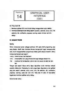
3. SystemC architecture While, from the users point of view, SystemC is mostly a C type syntax, its source code takes full advantage of C++ OOP possibilities. Figure 1 illustrates its object structure and the relation between objects. It is an abbreviated UML representation of SystemC. Note that italic means that a class is abstract or a method is virtual. A member preceded by "+", "-", or "#" means the member is public, private, or protected respectively.
2. Overview of SystemC
class T sc_signal
SystemC is not an extension of C++, it does not add any new syntax to C++. It is rather a new C++ class library, therefore it is just a matter of learning how to use the new classes to be able to model hardware design. These classes enable the user to define modules, processes, add communication through ports and signals that can handle a multitude of data types, ranging from bits, bit vectors, standard C++ types to user define types like structures. They also introduce timing, concurrency and reactive behavior [3]. Using SystemC requires knowledge of C and very little of C++. The approach is somewhat similar to VHDL or Verilog. This ensures that, a system level designer should be able to use SystemC rapidly. Some of the advantages of the SystemC design methodology are : • The design is written in only one language and does not need to be ported to another HDL possibly introducing discrepancies between the two version of the model. • The system can be modeled at a behavioral or architectural level then refined iteratively to the RTL. • Testbenches can be reused for all refinements of the design. However, keeping the use of C++ to a minimal has a drawback , it limits the possibility of taking advantage of the Object Oriented approach which would facilitate reuse, contributing to shorter design times, lower development costs and increased reliability [9]. During the development of our application, we used a model of the DLX processor [11] as a test case. This processor is a text book example of a RISC processor with a 5 stage pipeline using forwarding to avoid data hazards. In appendix B we illustrate the pipeline and discuss its implementation. We also give, in appendix C, sample code of one stage (MEM) in VHDL and SystemC to show that the language semantics are similar.
#update() +read() : class T
sc_simcontext -signals_to_update : sc_signal_base* * sc_signal_base -port_manager : sc_port_manager* -created_by : sc_object* -object_manager : sc_object_manager* +time_stamp() : double +update() +get_port_manager() : sc_port_manager* +get_object_manager() : sc_object_manager*
sc_port_manager
sc_object_manager
sc_object
+first_object() : sc_object* +next_object() : sc_object*
+name() : const char* +kind() : const char*
sc_port sc_module -port_vector:sc_pvector*
Figure 1 : Partial SystemC architecture The base class for signals, modules and clocks is sc_object, it contains basic methods and properties for identifying and classifying SystemC object. sc_signal_base is a specialization of sc_object which contains base methods and members for signals, it is an abstract class so it cannot be instantiated, only derived. sc_signal inherits from sc_signal_base, it is a specialization of the base class which has data of a template type and methods to manipulate this data. Class sc_simcontext is to our knowledge the simulation kernel, it contains methods like crunch() which loops through all the delta cycles necessary to advance to the next clock edge. This class also contains the list of signals to update, the simulation time and methods to start, stop or step the execution.
4. Controlling the simulation To achieve control, we need to change the call to SystemC sc_start(), that is made in the design model sc_main(), by the creation of our GUI window. Once the change is made, we can use a simulation menu to call SystemC functions sc_start() from there, using the appropriate step size as a parameter. See Appendix A for an example of the necessary changes to the sc_main(). Obtaining the simulation time is easy, using SystemC method sc_time_stamp(.) The value is then displayed in an appropriate QT widget [5]. We can get the list of the design’s modules directly from SystemC. The SystemC class sc_simcontext contains this information and has methods to access this information. We used the following methods : sc_get_curr_simcontext(); sc_simcontext::first_object(); sc_simcontext::next_object(); sc_object::name(); sc_object::kind(); Numerous SystemC classes, such as sc_signal and sc_module, are derived from the sc_object class. Using the first_object( ) and next_object( ) methods allows us to access the list of those objects, the kind( ) method permits us to distinguish between modules and other objects.
5. Accessing the list of the design signals We can get the list of signals in the same way. Unfortunately the list contains pointers towards objects of sc_signal_base type, which do not contain any data. Only objects of sc_signal type, which specializes sc_signal_base, contain data. This value is of a template type. An elegant solution is obtained by abstraction, SystemC designers used an sc_signal_base as an abstract class for the sc_signal and so they were able to create a list of « sc_signal_base * ». When they insert a pointer toward any signal type derived from sc_signal_base, its type is cast automatically. The problem we face is that even though we now have a pointer to an sc_signal_base, our GUI is not aware of what type the signal is. If we could know the type of signal, we could type cast the signal to its original form, (e.g.: (sc_signal *) signal) and then use any method from the original signal type. Because SystemC needed to update all the signals using a general pointers list, they defined a virtual
update(void) in the sc_signal_base class and by redefining a update(void) in SystemC sc_signal class; when this method is called from a generalized pointer, the appropriate update() is called according to the sc_signal data type and it is the signal responsibility to update itself. The problem is that the read() method, which returns the actual value of the signal is not virtual and is not in the base class. The reason is, that at no point, SystemC needs to read or modify the value of the signal. The signal is read and modified by the user who actually knows which type of signal he is dealing with since he created the signal. We would have liked to implement a new virtual read(), but this would require virtual template methods, which are forbidden in C++ [6]. We opted for the declaration of a new pure virtual method, notify_interface(), in the sc_signal_base class, which must be redefined in derived classes. When SystemC performs its crunch() cycle, we added a call to notify_interface() for every modified signals. So from there, it is the responsibility of the signal itself to notify the GUI of any change of status using this method. Since the signal knows its data type, it is an easy task to pass the value of the signal with the appropriate data type to the GUI.
6. Notifying the interface As stated previously, it is the signal responsibility to notify the GUI, but how can it notify the interface? One possibility is sending a message via a method to the GUI. Since SystemC is a standalone library and since we want our GUI to be independent from SystemC, how can we build the SystemC library without having to supply the GUI code to SystemC? Sending a message is usually done by calling a known method of the recipient class. How can we call this method if we do not supply the recipient class? In order to establish the communication between SystemC and the GUI, we defined an abstract class called sc_interface. We named this class following the general unwritten naming convention of SystemC. This class is abstract because one (in this case all) of its member methods is (are) pure virtual(s), so the class cannot be instantiate [2]. We do not want the class to be instantiated because this class has only one purpose: defining a standard for implementing derived classes. The derived class must implement every abstract method (pure virtual) before it can be instantiated. Once the interface class is well defined, we can compile SystemC and have it call methods that will be implemented later, in the GUI. In our case, the notify_interface() method of the sc_signal
class calls the appropriate update_signal() of the sc_interface class according to the data type. Since we cannot define virtual template methods [6], we were forced to « unroll » the template by prototyping every method with data type that the template would normally generate.
7. Interacting SystemC and the GUI We have also to define the way the sc_interface interacts with its derived class and SystemC. This is due to the fact that we cannot supply a reference of the derived class of sc_interface to SystemC since the class is not yet defined when we construct the SystemC library. Therefore we have to provide a pointer to the instance of the derived class, this is accomplished by having a static pointer in the abstract class to point to the instance of the derived class. The static member is common to all instances of the class (and derived classes) and can be used without having any instantiation of the class. We have implemented a method (namely sc_interface:: bind()) that binds the derived interface to SystemC by setting this static member (bound_instance). In our case, the derived class of sc_interface is named my_sc_interface. So upon instantiation of my_sc_interface, the constructor automatically calls the bind method. When SystemC executes initial_crunch() and the crunch() loop, a call to sc_interface::is_bound() is made, the return value indicates whether the user has attached an interface of his own or not. If a custom sc_interface is bound, the message sc_signal::notify_interface() is generated, and a call to sc_interface:: get_bound_instace() is issued to get the bound interface. The method update_signal() of this interface is then called (via polymorphism and inheritance) with the proper data type. We have yet to treat signals of a user defined type. For the moment, our method implies that the user has to make changes to the sc_interface class and implement method update_signal() in the derived class for those signals.
8. GUI prototype In our development, we chose Qt because it is a fully object-oriented, cross-platform C++ GUI application framework providing application developers with all the functionality needed to build GUIs [2]. Qt is available on a wide range of platforms including Linux and it is free for development of free/Open Source software under Unix/X11. Qt offers objects like menus, windows, buttons, etc. We also used the STL library [4] when
objects like lists, queues, and vectors were needed. This results in minimizing time for development as well as increasing code efficiency. For our first working prototype, we display Boolean signals traced and listed in windows as showed in Figure 2. As for integer signals, we have only listed them while showing the ability to customize the way each type of signals is rendered. We can do the same for each of the fundamentals C++ type but there is still work to do for the more complex SystemC basic types. For now, signal changes are memorized only if the user asked to visualize that signal. If the user has not selected a signal, its value is not recorded. The simulation speed is not affected by unselected signals. As soon as the user asks for a signal, the recording starts.
Figure 2 : Tracing a boolean signal Our GUI system is compiled independently from the end user’s project and is linked as a library. Only small modifications must be made to end users code to create the main window and then pass the execution control to it. If the user wants to be able to debug his signals with meaningful names, he must also attribute a name to each of his signal by modifying his code to use an undocumented SystemC signal constructor. Modifications to the user’s model are illustrated in appendix A.
9. Signals and ports hierarchy We are trying to improve the presentation of the simulation results by displaying the signals and ports by the modules that use them. Unfortunately, we have yet to succeed. We have tried getting the information on the module from the signal itself. Class sc_signal_base has a member created_by which is a pointer to the sc_object that created the signal. Strangely, that member is not initialized in most of the signals we have traced. For those who were,
created_by points to a sc_object whose members name and kind are not initialized. Thus, we have abandoned that approach. Another avenue which seems promising is approaching the problem from the modules point of view. Class sc_module has a member called port_vector. This seems to be a vector containing a list of the modules ports. Our next step is to explore this possibility.
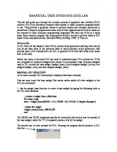
When tracing one signal (output), we observed that recording a signal leads to about 30% more time for the simulation then a cout that is redirected in a file. Whereas tracing the signal in a VCD file takes 320% the redirected cout time. These results are illustrated in Figure 4. 900
10. Cost in simulation speed
c
800 700 Elapsed time(us)
In order to evaluate the effect on simulation speed, we built a small model in SystemC, it contains output, a bool signal that changes value every positive clock edge, and the clock. We calculate the elapsed time between every cycle of the simulation and the starting time. For each test, we simulated for exactly 100 cycles in one uninterrupted step.
a) without modification
b d
600
b) 1 signal recording
500
a 400
c) 1 signal vcd wave tracing d) 1 signal cout redirected
300 200 100
89
78
67
56
45
Figure 4 : Keeping track of 1 signal
300 200 100
a) without modification
92
85
78
71
64
57
50
43
36
29
22
8
15
1
0
b) no interface bound
c) bound no recording
Figure 3 : No signal tracing We have tested the following cases : No modification to SystemC and no feedback (printf, cout or wave tracing). • SystemC modified to get the signals but interface not bound. • Interface bound but no signal recording. • No GUI, output signal traced using cout redirected to a file. • No GUI, output signal traced using cout to console. • No GUI, output signal traced in a vcd file. • Output signal recorded by GUI. • Clock and output signals recorded by GUI. We have found that, when no signal is traced, the modified SystemC is about the same speed as the original SystemC. While binding the interface will take 20% more time than the original SystemC as shown in Figure 3. •
34
Elapsed time
400
0 23
a b
500
1
c
12
600
It appears that we have a significant increase when using the GUI, however, we gain in flexibility of viewing the results. Simulating with cout may lead to loss of first results if the amount of output lines exceeds the number available in the console window, also, if we need to keep track of several signals, their output will be all in the same window and might be difficult to sort out, as such, a GUI that permits to view signal by signal is an improvement. Also, since we have tested using cout that are redirected to a file, this means that results can be viewed after the simulation, when the output is written directly in the console, the simulation time increases dramatically, to about 280% of the time for the redirected output.
11. Conclusion We have described an experiment of adding a GUI to SystemC simulation and offered a brief description of our implementation to aid developers who wish to create their own interface. We have found that in its official form, SystemC lacks in its accessibility to the data, every value being private. Fortunately, it is an open system, so it is possible to modify the source code to suit our needs. We have found that our GUI seems to require less simulation time than most way of obtaining a signal results, except for a cout that is redirected in a file which can be viewed only after the simulation. In that case, we
think that the extra time is a good trade-off for a better flexibility in viewing the results. We plan on generalizing our interface class to link SystemC to other applications by changing SystemC as little as possible, by using design patterns which are a methodology borrowed from software engineering techniques for software reuse [8]. We will then submit the changes we made to SystemC to the OSCI, hoping that they will incorporate them in an their future releases.
Appendix A // bold and italic indicate changes #include #include "visualSC.h" #include "test.h" int sc_main(int ac, char *av[]) { //pointer to application object QApplication *application;
12. References J. Gerlach and W. Rosenstiel, "System Level Design Using the SystemC Modeling Platform", Worshop on System Design Automation SDA 2000, pp. 185-189. [2] S. B. Lippman and J. Lajoie, C++ Primer, 3/e: Addison Wesley, 1998. [3] Open SystemC Initiative (OSCI), SystemC version 1.1 beta documentation: http://www.systemc.org, 2000. [4] Silicon Graphics Computer Systems, Standard Template Library Programmer’s Guide: http://www.sgi.com/Technology/STL, 1999. [5] Trolltech AS, Qt On-Line Reference Documentation: http://doc.trolltech.com, 2000. [6] Publications by Bjarne Stroustrup: http://www.research.att.com/~bs/papers.html, 2000. [7] Electronic News Online , “OSCI changes terms of SystemC license”, march 1 2000, http://www.electronicnews.com/news/263761NewsDetail.asp [8] E. Gamma, R. Helm, R. Johnson, and J. Vlissides, Design Patterns: Elements of Reusable Object-Oriented Software: Addison Wesley, 1994 [9] Sanjaya Kumar, James H. Aylor, Barry W. Johnson,Wm. A. Wulf, The Codesign of Embedded Systems A unified hardware/software representation, Kluwer Academic Publishers, 1996, 274 pages [10] L. Charest, M. Reid, E.M. Aboulhamid and G. Bois, “A Methodology for Interfacing Open Source SystemC with a Third Party Software”, DATE2001, 5 pages, Munich, 2001 [11] J. Hennessy, D. Patterson, Computer Architecture A Quantitative Approach, 2/e, Morgan Kaufmann, 1996
//pointer to visualSC’s main window MainWindow *mainWindow;
[1]
//Creation of a single signal sc_signal output("output"); //Creation a clock object sc_clock clk("clk", 50, 0.5, 0,true); //instance of ’test’ module Test test("test"); //Named port binding test.clk(clk); test.output(output); //SystemC model without printf or cout //call to create visualSC’s mainwindow MainWindow::CreateMainWindow(&application, &mainWindow, ac, av); //put this sc_start() in comment //sc_start(-1); /*Here visualSC takes control. Note the simulation does not start immediately, only when the user clicks start */
bool success = application->exec(); return success; }
A typical model using the GUI capability
Appendix B Clk
IF IF_ID_op
ID
ID_EX_op
MEM
EX
MEM_WB_IR
WB
EX_MEM_IR
ID_EX_IR
MEM_WB_NPC
IF_ID_IR
EX_MEM_B ID_EX_A
PC
EX_MEM_NPC
reg
ID_EX_B IF_ID_NPC ID_EX_Imm Forwarding registers
MEM_WB_LMD
/
MEM_WB_ALUOutput
ID_EX_cond EX_MEM_ALUOutput ID_EX_NPC sig_trap RAM
Figure 5 : DLX implementation
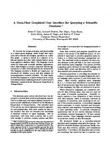
The DLX implementation consists of five modules that form individual stages of a pipeline. These are : • IF : Instruction Fetch • ID : Instruction Decode • EX : Execution stage • MEM : Memory access stage • WB : Write Back Each module contains a corresponding process. Communication between modules are made via ports which are showed in Figure 5. The processes are executed concurrently. Ports looping to an earlier stage represent data forwarding to decrease data hazards.
Structural hazards are managed by automatic insertion of a stall ( nop instruction ). The instruction set we implemented consists of 54 instructions : the integer arithmetic, logical, shift, set-oncomparison, jump and branch, load and store and some special instructions : nop and trap. The program to be executed on the DLX is in a file whose name is passed via parameter to the main function. The IF module then uses the content of that file to initialize the instruction memory. The RAM is part of the MEM module. Models of the DLX in SystemC and VHDL can be obtained from www.iro.umontreal.ca/labs/lasso/DLX.
Appendix C Based on Figure 5 with few adjustments, we have implemented the DLX in SystemC and VHDL. A comparison of the MEM stage in VHDL and SystemC show a similar semantic. Most differences are due to the fact that these implementations were developed independently. The VHDL model includes one entity and one behavioural architecture that contains five processes that form the stages of the pipeline. Therefore, contrary to SystemC, no ports are needed to communicate between the processes. The VHDL implementation had an additional constraint : the process was to read the signals values on the negative edge whereas the on the positive edge, output signals were updated. This constraint could not be respected in the SystemC model. We see from this comparison that VHDL is a strongly typed language, accessing the RAM requires two type conversions to obtain the array subscript. entity dlx is end dlx; library ieee; use ieee.numeric_bit.all; use work. dlx_types.all; use work.dlx_instr.all; architecture behavior of dlx is . . .
DLX_MEM:process(Clk) variable IR : dlx_bv_word; variable ALUOutput : dlx_bv_word; variable LMD : dlx_bv_word; variable B : dlx_bv_word; begin if Clk = ’0’ then IR := EX_MEM_IR; ALUOutput := EX_MEM_ALUOutput; B:= EX_MEM_B; if IR(0 to 5) = op_lw then LMD:=RAM(to_integer(unsigned(ALUOutput)/4)); else if IR(0 to 5) = op_sw then RAM(to_integer(unsigned(ALUOutput)/4))