2124
IEEE TRANSACTIONS ON COMMUNICATIONS, VOL. 49, NO. 12, DECEMBER 2001
Improved Spatial-Temporal Equalization for EDGE: A Fast Selective-Direction MMSE Timing Recovery Algorithm and Two-Stage Soft-Output Equalizer Hanks H. Zeng, Member, IEEE, Ye (Geoffrey) Li, Senior Member, IEEE, and Jack H. Winters, Fellow, IEEE
Abstract—The radio interface EDGE (Enhanced Data rates for Global Evolution) is currently being standardized as an evolutionary path from GSM and TDMA-IS136 for third-generation high-speed data wireless systems. For the EDGE system with multiple antennas, spatial-temporal equalization (STE) can reduce intersymbol interference and co-channel interference, thereby increasing the capacity and range. In this paper, we propose two new techniques to improve the performance of a previously proposed STE: a fast timing recovery algorithm for a selective time-reversal equalizer and a two-stage soft-output equalizer. The new timing recovery algorithm determines the estimated burst timing and processing direction by computing the minimum mean-square error (MMSE) for decision feedback equalizers in both the forward and reverse time directions. The two-stage soft-output equalizer is the cascade of a delayed decision-feedback sequence estimator (DDFSE) and maximum a posteriori probability (MAP) estimator. The DDFSE provides better noise variance estimation and channel truncation for the following MAP. The performance of the new STE is evaluated for the EDGE. At 10% block error rate, the two-branch receiver requires a 3–7-dB lower signal-to-interference ratio (SIR) than the previous approach. Compared with the one-branch receiver, the two-branch receiver requires a 4-dB lower SNR with noise only, and a 10–27-dB lower SIR with a single interferer. Index Terms—Adaptive antennas, soft-output detection, spatialtemporal equalization, time-reversal equalization, timing recovery.
I. INTRODUCTION
T
HE radio interface EDGE, Enhanced Data rates for Global Evolution, is currently being standardized as an evolutionary path from GSM and TDMA-IS136 for third-generation high-speed data wireless systems [1], [2]. A major limitation on the system range and capacity of wireless systems such as EDGE is intersymbol interference (ISI), caused by multipath fading, and co-channel interference (CCI). Spatial-temporal equalization (STE) using multiple antennas is an efficient approach to jointly suppress ISI and CCI [3]–[9]. A popular STE structure uses space–time prefilters for combining, followed by a temporal equalizer for signal detection Paper approved for publication by R. A. Kennedy, the Editor for Data Communications Modulation and Signal Design of the IEEE Communications Society. Manuscript received February 2, 2000; revised November 13, 2000. This paper was presented in part at VTC 2000 and at WCNC 2000. H. H. Zeng is with the Intel Corporation, Morganville, NJ 07751 USA (e-mail:
[email protected]). Y. Li is with the School of Electrical and Computer Engineering, Georgia Institute of Technology, Atlanta, GA 30332-0250 USA. J. H. Winters is with the Wireless Systems Research Department, AT&T Labs-Research, Middletown, NJ 07748 USA. Publisher Item Identifier S 0090-6778(01)10622-7.
(see Fig. 1). The optimal solution in the sense of minimum bit error rate (BER) for the prefilters is to maximize the combiner output signal-to-interference plus noise ratio (SINR) at each frequency [9]. Due to practical constraints, suboptimal approaches have been proposed [3], [4]. In [4], prefilter coefficients are obtained by maximizing the overall SINR at the combiner output. In [3], prefilters are viewed as the feedforward filters of a decision-feedback equalizer (DFE), and the receiver is trained as if it was a DFE.1 In this paper, we propose a new timing recovery algorithm and a two-stage soft-output equalization structure to improve the performance of the STE in [3]. 1) Timing Recovery. In EDGE systems, the burst and symbol phase at the receiver vary from burst to burst due to multipath fading and sampling clock variation. Burst and symbol timing recovery is crucial for good equalizer performance especially when the prefilter length is short because of the limited number of training symbols. In addition, since the impulse responses of fading channels are usually not symmetric, a selective time-reversal nonlinear equalizer can improve the performance [11]–[13]. In [11], a timing recovery algorithm based on an exhaustive search method is proposed to determine the estimated burst and symbol timing and to select the processing direction as either the forward or reverse time direction. However, this method requires multiple equalizer training which is computationally costly in EDGE systems. In contrast to the exhaustive search method, fast computation of the mean-square error (MSE) for a DFE has been developed by exploring the DFE structure [14], [15]. One of the main contributions in this paper is to extend the above method to a selective time-reversal equalizer in EDGE. Our new timing recovery algorithm computes the MSEs in both the forward and reverse time directions. The estimated burst and symbol timing as well as the processing direction are then selected to minimize the MSE. 2) Soft-Output Equalization. For the temporal equalizer in Fig. 1(a), the optimal solution in the sense of minimum BER is the symbol-by-symbol maximum a posteriori probability (MAP) estimator [16] which delivers soft1In [3], it is shown that the feedforward filter of the MLSE behaves similarly to the feedforward filter of the infinite-length DFE at high SNR. However, this does not extend to the finite-length case. As a result, our training method is not optimal. However, the gap between this approach and the optimal solution should be small (see the discussion in [3]). The idea of using the DFE criterion for the prefilter design has also been proposed for a one-branch (one-antenna) DDFSE in GSM [10].
0090–6778/01$10.00 © 2001 IEEE
ZENG et al.: IMPROVED STE FOR EDGE
2125
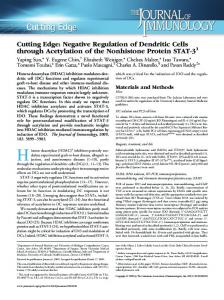
Fig. 1. (a) EDGE system diagram. (b) EDGE slot structure.
output information to the outer convolutional decoder [17]. In EDGE, the 8-PSK modulation and long channel memory (about 7 taps) results in a computationally complex MAP estimator. For complexity reduction, one can use suboptimal approaches such as the soft-output Viterbi algorithm (SOVA) [18], Max-Log-MAP [19], Log-MAP [20], reduced-state soft-output equalization [21], and soft-output DDFSE [3], [22]. Among the above approaches, SOVA and Max-Log-MAP are not as effective with nonbinary modulation [23]. The other approaches perform well when good noise variance estimation is provided prior to equalization, but mismatch of the noise variance significantly degrades the decoder performance [24]–[26]. In this paper, we first investigate the soft-output DDFSE and show that the noise variance estimation is biased. Next we propose a new two-stage soft-output equalizer which is the cascade of a DDFSE and MAP. The two-stage soft-output equalizer uses the final-decision symbols from the DDFSE to estimate the noise variance and truncates the channel memory for the MAP estimator. Compared with the soft-output DDFSE, the two-stage soft-output equalizer reduces both the feedback symbol errors and the noise variance estimation error. With the new timing recovery algorithm and the two-stage softoutput equalizer, the modified receiver significantly improves the raw BER and block error rate (BLER) performance compared with the previous approach [3]. Compared with the one-branch (one-antenna) receiver, the modified two-branch (two-antenna) receiver requires a 4-dB lower SNR at a 10% BLER, and 10–27-dB lower SIR depending on the channel characteristics.2 2The simulation results in this paper are under a no-frequency-hopping assumption. With frequency hopping, the receiver performance will be improved.
The rest of this paper is organized as follows. In Section II, we introduce the EDGE transmitter and receiver architecture. In Section III, we derive the fast timing recovery algorithm. In Section IV, we propose the two-stage soft-output equalizer. In Section V, we demonstrate the performance improvement of our receiver via extensive simulations. Conclusions are given in Section VI. II. SYSTEM OVERVIEW Fig. 1(a) shows the EDGE transmitter and receiver architecture. We briefly describe each function block in this section. EDGE uses nine different modulation and coding schemes (MCS) to support packet data communications under different channel conditions [2]. In this paper, we study the receiver performance using MCS-5. Similar results can be extended to other MCS modes. In MCS-5, the incoming data bits, delivered in convolutional code 20-ms blocks, are encoded using a rate with a constraint length of 7. The coded bit stream is punctured and interleaved for protection against fading. The interleaved bits and header field bits (header, uplink status flag, stealing bits) are distributed over the four bursts of 577 s. The burst format is the same as GSM [see Fig. 1(b)]. The modulation is 8-PSK with linearized GMSK pulse shaping, and the baud rate is 270.833 K symbols per second. In the receiver, baseband signals are filtered using square root raised cosine filters with a bandwidth of 180 kHz and roll-off factor of 0.5. The open-loop AGC normalizes the received signals by their average power in a burst. In addition to the symbol phase adjustment, the timing recovery block also estimates burst timing (i.e., equalizer delay) and decides the processing direction (i.e., forward and reverse time directions) for the selective
2126
IEEE TRANSACTIONS ON COMMUNICATIONS, VOL. 49, NO. 12, DECEMBER 2001
Fig. 2. (a) Fixed-directional equalization. (b) Selective directional equalization.
directional equalizer which processes each received burst in either the forward or reverse time direction. The prefilters, each symbol-spaced taps, combine the two-branch rewith ceived signals to suppress CCI and noise. The channel impulse taps. response for the desired signal is also shortened to As a result, at the output of the combiner, the system can be viewed as an ISI channel with additive noise. The shortened ISI channel is further equalized by a soft-output equalizer which includes a DDFSE and MAP estimator. The soft-output of the MAP estimator is de-interleaved and decoded via a Viterbi con) volutional decoder. The prefilter coefficients (denoted as and the shortened channel impulse response (denoted as ) are calculated in the training block. The equalizer is trained as if as the feedforward filters and as it was a DFE with the feedback filter [3]. To improve the convergence, the direct matrix inversion algorithm [27] is used. In summary, the receiver structure is similar to that proposed in [3], except for the timing recovery and soft-output equalizer blocks which will be described in detail in the following sections. III. TIMING RECOVERY The main task of timing recovery is to determine the symbol phase, burst timing, and processing direction. In this section, we first describe the minimum precursor timing recovery scheme proposed in [3], [28]. Next we develop a fast timing recovery algorithm based on efficient computation of the MMSE for the selective directional DFE. A. Minimum Precursor Energy (MPE) Timing Recovery Algorithm As shown in Fig. 2(a), the training symbols in EDGE are at the middle of each burst. The equalizer for data2 works in a normal sequence, from the beginning of the sync to the end of the burst, while the time-reversal equalizer for data1 operates from the last sync symbol to the beginning of the burst. For each direction, symbol phase and equalizer delay are determined to minimize the ratio of precursor to cursor energy [28]. In this paper, the above scheme is referred to as the minimum precursor energy (MPE) timing recovery algorithm. Note that the processing direction is fixed in the MPE timing recovery algorithm. data2 is always processed by the equalizer in the forward time direction, while data1 is processed in the
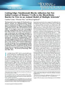
Fig. 3. (a) Error bit distribution. (b) The channel impulse response. (c) MSE of a T -spaced DFE versus delay and direction. SNR = 40 dB. SIR = 5 dB; two antennas; five prefilter taps; five feedback filter taps.
reverse time direction. However, when the channel impulse response is not symmetric, the BER may be unequal for the two equalizers. Fig. 3(a) and (b) shows the bit error distribution in a burst and the corresponding channel response in the burst. (The detailed simulation conditions can be found in Section V.) Bits 1-174 and bits 175-348 correspond to data1 and data2, respectively. data1 has more errors than data2. The reason is the channel impulse response. For the forward time direction, the DFE uses the strong first path to cancel the ISI caused by the weak delayed path. For the reversed time direction, the channel impulse response is time-reversed, and thus the DFE uses the weak path to cancel the strong path, resulting in poorer performance due to noise enhancement. In Fig. 3(c), we plot the MSE versus the equalizer delay for both directional equalizers with the symbol phase of 0. Over a wide range of delays, the MSE for the DFE in the forward time direction is less than that of the time-reversal DFE. The optimal equalizer delay is 13 symbol intervals in the forward time direction. Note that a nonoptimal choice of delay or direction can result in a significant MSE increase. The above example shows that equalizer performance is sensitive to the processing direction and equalizer delay in a fading environment. Timing errors can result in a significant performance degradation.
ZENG et al.: IMPROVED STE FOR EDGE
2127
B. Fast MMSE Timing Recovery Algorithm To overcome the problems in the MPE algorithm, we derive a fast MMSE timing recovery algorithm for the selective directional equalizer. As shown in Fig. 2(b), the selective directional equalizer operates in a preselected time direction. In contrast to previous timing recovery approaches using multiple trainings [11]–[13], our approach is based on an efficient MMSE computation of the DFE, and thus is more computationally efficient. The new algorithm basically finds a delay-and-direction-optimized MMSE-DFE. Below, we first derive the MSE computation algorithm [14], [15] for the DFE in the forward time direction. Then we extend the method for the time-reversal DFE. As shown in Fig. 4, the baud spaced received signal sample at the AGC output in th branch is given by
..
..
.
.
.. . ..
.
(5) ..
.
For convenience, define the feedforward and feedback coefficient vectors as follows: (6) (7)
(1)
Under the assumption of correct past decisions, the error in the slicer input is given by
is the th channel impulse where is the transmitted desired symbol, response after the AGC, is the sample of the interference plus noise. The DFE and -tap feedforward filters and an -tap feedback has filter. The slicer input is given by
(8) and are considTo derive the optimal values of ered as the input and desired signal, respectively. From adaptive filter theory [29, p. 170], the MSE is given by
(9) (2) denotes complexwhere integer is the equalizer delay and conjugate transpose. Using vector representation, we have (3)
is the covariance matrix of the where noise vector, and the transmitted signal samples are assumed . We partition to be uncorrelated, i.e., according to
where (10)
.. . .. .
th diagonal element, is the th diagonal element, is the by subblock of whose upper left element corresponds to th diagonal element, is the by 1 vector by 1 vector right above . The right below , and is the MSE and MMSE at delay are then given by where
.. .
.. .
is the
.. .
(11) (12)
.. .
respectively. The estimated equalizer timing is the one that . minimizes From the above discussion, we need to calculate the and ’s to obtain the delay estimation for the forward several and ’s can also DFE. Below, we show that the above be used for the time-reversal DFE. In the time-reversal DFE, the received signal samples and the transmitted symbols are reversed in time. The corresponding channel impulse is also reversed. Let
.. . (4) .. .
2128
Fig. 4.
IEEE TRANSACTIONS ON COMMUNICATIONS, VOL. 49, NO. 12, DECEMBER 2001
A baseband channel and DFE.
, where the overbar implies a time reversal system. It is straightforward to verify that (13) To derive the MSE of time-reversal DFE, it is convenient to define the transform (14) flips the rows of with a given dimension. For a matrix from top to bottom. Similarly, flips the columns of from left to right. It can be shown that (15) , we have
By choosing
(16) The corresponding MMSE is given by
SIR, the estimation of the interferer is more important since the equalizer delay should be adjusted to cancel the strong interferer. This is in the contrast to the MPE algorithm which uses solely the channel estimation. IV. SOFT-OUTPUT EQUALIZATION In this section, we study the temporal equalizer which delivers soft outputs to the outer convolutional decoder. We first review the soft-output delayed decision-feedback sequence estimator (DDFSE) algorithm [3] and show that the noise variance estimation is biased. To avoid this problem, we propose a new two-stage soft-output equalizer structure. A. Performance Analysis of the Soft-Output DDFSE 1) System Model: As shown in Fig. 1(a), the STE has prefilters followed by a temporal equalizer. The prefilters suppress noise and interference and also shorten the overall system impulse response to reduce the computation complexity of the temporal equalizer. At the prefilter combiner output, the system can be viewed as an ISI channel given by
(17) is involved in the MMSE calAs seen from (12) and (17), culation for both directions, and thus only one matrix inversion is required. The algorithm is summarized as follows: The MMSE Timing Recovery Algorithm 1. Estimate the channel channel matrix
using the sync word by the least square method. Construct
according to (5).
(18) is defined where the shortened channel impulse response as the feedback filter coefficients of the DFE, i.e., , and the noise is defined as
2. Subtract the desired signal from the received signal and estimate the covariance matrix as follows:
where
(19)
is constructed from the sync symbols according to (4).
3. Compute
matrix according to (9). and
4. Compute the range of
from
5. Find the minimum of
according to (12) and (17), respectively, over to
and
. to determine the estimated delay
and direction.
Note that the dimension of is the feedback filter length . This approach is efficient when the feedback filter length is short. Remark: In the presence of a strong interferer, although the channel estimation error for the desired signal is large, we . In fact, at low have good estimation of the interference
which includes residual ISI, CCI, and noise. The noise variance . is 2) Soft-Output DDFSE Structure: As shown in Fig. 5(a), the soft-output DDFSE [3] is a reduced-state MAP algorithm which applies a MAP in the MLSE portion of the DDFSE. The first is handled by the MLSE via the Viterbi part of the channel are canalgorithm (VA), while the remaining postcursors celled by delayed tentative decisions for each state. Thus, the channel state is reduced to a hyperstate corresponding to . In parallel to the MLSE, a MAP estimator computes the soft outputs based on these hyperstates in the MLSE.
ZENG et al.: IMPROVED STE FOR EDGE
2129
(a)
(b) Fig. 5. (a) Soft-output DDFSE. (b) Two-stage soft-output equalizer.
3) Performance Analysis: The performance of the softoutput DDFSE is affected by the following factors: 1) white Gaussian assumption for the noise; 2) equalizer parameter generation error; 3) feedback symbol errors (i.e., incorrect tentative decisions); and 4) noise variance estimation error. is white if an infinite length For factor 1), ideally, MMSE-DFE is used and the CCI is Gaussian. In the case of a finite-length filter and non-Gaussian CCI, the approximation error should cause a small performance degradation as shown in [4]. For factors 1) and 3), both errors enhance residual ISI, CCI and noise, thereby reducing the input SNR of the MAP estimator. For factor 4), it is well known that the BER performance of the MAP is very sensitive to the noise variance estimation, especially to underestimation [24]–[26]. In the soft-output DDFSE, is the MSE of the DFE [see (18), (2) and the noise variance (8)]. The estimated noise variance is obtained during the training as follows [3]:
(20) is the sync word. The above estiwhere from the mean-square error mation basically approximates during the training. However, it can be shown that such an esti-
mator is biased (underestimated),3 which results in a substantial performance degradation. B. Two-Stage Soft-Output Equalizer To overcome the drawbacks of the soft-output DDFSE, we propose a new two-stage soft-output equalizer structure which reduces the feedback symbol errors and the noise variance estimation error. 1) Structure: Note that knowledge of the noise variance is required for MAP detection. However, such information is not necessary for hard-decision algorithms such as MLSE and DDFSE. As shown in Fig. 5(b), the proposed structure is the cascade of a DDFSE and MAP. The DDFSE produces and a noise variance estimate . hard-decision outputs The shortened channel impulse response is further truncated is then handled using hard decisions. The truncated channel by a MAP estimator. The complexity of the MAP is constrained by the parameter which is controlled independently of . , the two-stage soft-output For different choices of equalizer has various structures: : • A full state MLSE and MAP is used when both and are equal to the channel memory length . Optimal soft outputs are delivered by the MAP, while the first stage of the MLSE provides the noise variance estimates. This structure is the most computationally complex one. 3As an extreme case, when the total number of equalizer coefficients is greater than or equal to the number of training symbols, the training error in (20) is zero.
2130
IEEE TRANSACTIONS ON COMMUNICATIONS, VOL. 49, NO. 12, DECEMBER 2001
•
: This choice is equivalent to a DFE followed by a one-tap MAP. This structure is similar to that in [30]. The one-tap MAP can be implemented using a simple averaging function instead of the recursion used in the standard MAP algorithm. The DFE hard decisions are used to cancel all the postcursors. The feedback cancellation between the DDFSE and MAP can be omitted. This structure is the simplest one. However, both the feedback symbol errors and noise variance estimation error are large. : • In between the above choices, various forms can be obtained to tradeoff complexity and performance. 2) Noise Variance Estimation: For the noise variance estimation, we consider the equivalent model at the input of the MAP. According to Fig. 5(b) and (18), we have
it is obtained in the data period. It also utilizes the results of the DDFSE. Therefore, it is more accurate. 3) Soft-Output Recursion: To complete the description of the two-stage soft-output equalizer, we derive the soft-output computation using Lee’s algorithm [31], [17]. The transmitted 8-PSK symbol can be expressed as (25) , and the function performs the 8-PSK where modulation and Gray mapping. The soft output is the a posteriori probability (APP) defined as the conditional probability of given the received samples , i.e., each bit
(26)
(27)
(21)
is defined in (28) and (29), where shown at the bottom of the page. Each term of (28) and (29) is obtained recursively by
where (22) is the noise including the additive noise at the prefilter output can be estimated and the decision errors. The variance of by averaging over only the data as follows:
(23) According to (18), we have (24) Equation (24) is the accumulated error metric corresponding to the final decision symbols which can be computed using the hard decisions of the DDFSE. Compared with the previous estimation method using equalis averaged over more samples since izer training error (20),
(30) is the estimated noise variance given by DDFSE (24), where and is a constant. Note that (30) can be implemented in the logarithmic domain similar to the Log-MAP algorithm [20]. Remarks: • The effect of the SNR mismatch on the turbo decoder and MAP decoder has been studied in [24]–[26]. Various approaches have been proposed to reduce the sensitivity to SNR mismatch. Compared to these approaches, our two-stage soft-output equalizer not only reduces the noise variance estimation error, but also provides more accurate feedback symbols for the channel truncation. • There are also iterative equalization and decoding techniques such as turbo equalization and turbo space-time processing [32]–[34] that can improve the receiver performance. In [34], the coded layed space–time approach with known channel parameters was shown to achieve a performance within about 3 dB of the channel capacity. In [33], the channel parameters including the noise variance are refined in the decoding iteration. However, compared to our
(28) (29)
ZENG et al.: IMPROVED STE FOR EDGE
2131
approach, the iterative equalization/decoding approach is more computational complex. V. RECEIVER PERFORMANCE In this section, the performance of the MMSE timing recovery algorithm and two-stage soft-output equalizer are evaluated for the EDGE system. We first describe the simulation environment and then show the results. A. Simulation Environment The simulation environment is based on the EDGE system described in Section II. The channel model is a multipath fading channel with the GSM typical urban (TU) and hilly terrain (HT) profiles. In our simulation, we assume that the Doppler frequency is 4 Hz, which corresponds to a pedestrian environment. No frequency hopping is assumed. The SNR is defined as
Fig. 6. Performance comparison of timing recovery algorithms with two antennas and the HT profile.
(31) is the signal power, is the noise floor, is the bit where energy, is the number of bits per symbol, and is the baud (dB). rate. For 8-PSK modulation, We consider a single interferer which has the same burst timing as the desired signal, but the relative symbol phase is random. This case is close to the EDGE compact system whose base stations are synchronized. The interference is measured by the SIR defined as the ratio of the signal power to the noise power measured at the antenna input. The fading channel of the interferer is independent of the desired signal’s channel. The fading between receiver antennas is assumed uncorrelated. The prefilter and the feedback filter have five taps each . The equalizer uses an eight-state DDFSE and . To evaluate the receiver pereight-state MAP formance, we determine the raw BER at the DDFSE output and BLER at the convolutional decoder output. B. Performance of the MMSE Timing Recovery Algorithm Fig. 6 shows the raw BER versus SIR for a two-branch receiver with the HT profile. The results are shown for the MMSE timing recovery algorithm described in Section III-B (circle) and the MPE timing recovery algorithm described in Section III-A (square). In addition, two ideal curves are plotted for reference: trained equalizer with perfect MMSE timing recovery (plus) and perfect training with perfect MMSE timing recovery (triangle). Furthermore, to separate the effect of the time reversal operation and the MMSE criterion, we also plot the curve for the MMSE timing recovery algorithm with the BER, the forward direction search only (cross). For a required SIR with the MMSE timing recovery algorithm is 5 dB less than that required with the MPE approach. Note that this SIR is 2 dB higher than that required with perfect MMSE timing recovery. As the BER decreases, this degradation decreases since the channel estimation used for timing recovery becomes more accurate. With perfect training and timing, the required SIR for a 10 BER is about 15 dB less than that with the trained equalizer and the MPE timing. About half of this
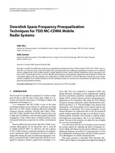
degradation is due to imperfect timing recovery, demonstrating the importance of the MMSE timing recovery. Next we study the effect of symbol timing error for the MMSE timing recovery algorithm. We simulate the raw BER versus SIR for one and two antennas with -spaced and -spaced symbol timing quantization. For the -spaced case, . we also set four different symbol phases The results show that the variation in SIR due to the symbol -spaced quantization, the symbol phase is about 1 dB. For phase needs to be determined prior to the -spaced STE. The computation complexity is four times that of the -spaced case, but the performance gain is not significant. In our simulation, -spaced quantizathe required SIR for a given BER using tion is about 1 dB less than that using -spaced quantization. C. Performance of the Two-Stage Soft-Output Equalization The system configuration for the soft-output equalizer comdB, two antennas, parison is as follows: TU profile, and the MMSE timing recovery algorithm. The soft-output DDFSE (Section IV-A) and two-stage soft-output equalizer (Section IV-B) are compared. For the soft-output DDFSE, the noise variance estimate is given by (20). To verify that the noise variance estimate of the soft-output DDFSE is underestimated, we artificially enlarge it by a factor (32) Fig. 7 shows the BLER versus SIR for the two-stage softand , output equalizer, the soft-output DDFSE with the soft-output DDFSE with perfect noise variance estimation, and the soft-output DDFSE with perfect noise variance estimation plus perfect feedback. For the soft-output DDFSE, the noise variance estimation error and feedback errors cause about a 3.3-dB loss each in required SIR for a 1% BLER, demonstrating the importance of the noise variance estimation and feedback. As indicated in Section IV-A, by increasing to 5, the required SIR is reduced by 2.2 dB. On the other hand, the two-stage soft-output equalizer significantly reduces both the
2132
Fig. 7. Performance of the soft-output DDFSE (SO-DDFSE) and two-stage soft-output equalizer.
IEEE TRANSACTIONS ON COMMUNICATIONS, VOL. 49, NO. 12, DECEMBER 2001
Fig. 9. BLER versus SIR.
Fig. 10. BLER versus SNR. Fig. 8. Raw BER versus SIR.
noise variance estimation error and feedback errors. The performance improvement over the soft-output DDFSE is about 5 dB, which is within 1.5 dB of that of the soft-output DDFSE with perfect noise variance estimation and feedback. D. Performance of the Modified Receiver In this section, the performance of the modified receiver using the MMSE timing and two-stage soft-output equalizer is evaluated for various channel environments. Comparisons between the modified receiver, the receiver using perfect timing and perfect training (with the same number of taps), and the previous approach using the MPE timing and soft-output DDFSE are also made for some cases. 1) Performance Gain of the Modified Two-Branch Receiver: We first consider the performance of the modified receiver for one and two antennas in Figs. 8–10. Table I summarizes the required SIR and SNR for a 10% BLER. For the noise-only case, the two-branch receiver provides about a 4-dB SNR reduction for both the TU and HT profiles. For the
interference-only case, the two-branch receiver provides about a 10-dB SIR reduction for the HT profile and 27 dB for the TU profile. 2) Comparison Between the Modified Receiver and the Previous Receiver: Next we compare the performance of the modified receiver and the previous one with one co-channel interferer. Figs. 8 and 9 show the raw BER and BLER versus SIR. Note that the raw BER improvement is due to the improvement of the timing algorithm, while the BLER gain comes from the improvements of timing as well as the soft-output equalizer algorithm. The results are summarized as follows. • For the two-branch case, the required SIR for a 1% raw BER and 10% BLER using the modified receiver is about 3–7 dB lower than that required using the previous receiver. • For the one-branch case, the modified receiver has about 2 dB improvement (in required SIR for a given raw BER and BLER) as compared to the previous receiver for the TU profile. For the HT profile, the improvement is even greater. The previous receiver has a BER floor around
ZENG et al.: IMPROVED STE FOR EDGE
2133
TABLE I REQUIRED SNR AND SIR FOR A 10% BLER
and a BLER floor around 20%, while no error floor is seen for the modified receiver. 3) Comparison Between the Modified Receiver and the Receiver Using the Perfect Timing/Training: With noise only, the performance improvement of the two-branch modified receiver is about 4 dB. In Fig. 10, we also show the corresponding results of the receiver using perfect timing/training (with the same number of taps). The result shows the potential improvement with better techniques. For a 10 BLER, the two-branch receiver using perfect timing/training requires 7–8 dB lower SNR than the one-branch receiver. Comparing the modified receiver with the receiver using the perfect timing/training, the one-branch case has a 2–3-dB loss and the two-branch a 6–7 dB loss. The large degradation of the two-branch receiver is due to the fact that the two-branch receiver has more equalizer coefficients (15) to be calculated than the one-branch receiver (10), which leads to a large training error with only 26 training symbols. This problem becomes even worse when the number of antennas is further increased. To mitigate this problem, modification of the training method using the diagonal loading4 or the subspace method [35], and channel estimation-based training [36] can be used. VI. CONCLUSION In this paper, we have proposed a fast selective-direction MMSE timing recovery algorithm and two-stage soft-output equalizer structure for spatial-temporal equalization. The new timing recovery algorithm computes the MMSE for the DFE in both the forward and reverse time directions and determines the estimated burst timing and processing direction. The twostage soft-output equalizer is the cascade of a DDFSE and MAP estimator. It uses the final-decision symbols from the DDFSE to estimate the noise variance and truncates the channel memory for the following MAP estimator. Compared with the soft-output DDFSE, the two-stage soft-output equalizer reduces both the feedback symbol errors and the noise variance estimation error. The performance of the modified receiver using the MMSE timing recovery algorithm and two-stage soft-output equalizer was evaluated for EDGE. For a 10% BLER, the modified receiver using two antennas requires 4 dB lower SNR and 10–27 dB lower SIR than a single-antenna receiver. Compared with the previous STE [3], the performance improvement is 3–7 dB in SIR. 4We obtained a 1–2 dB improvement with the HT profile using diagonal loading with a fixed (optimized per case) loading factor. Further improvement with a modified diagonal loading technique appears possible.
ACKNOWLEDGMENT The authors would like to thank S. Ariyavisitakul and H. Sadjadpour for their helpful discussions and to N. Sollenberger for his encouragement. The authors are also grateful to the anonymous reviewers for their insightful comments that significantly improved the quality of the paper. REFERENCES [1] A. Furuskar, S. Mazur, F. Muller, and H. Olofsson, “EDGE: Enhanced data rates for GSM and TDMA/136 evolution,” IEEE Personal Commun., vol. 6, pp. 56–66, June 1999. . [2] N. R. Sollenberger, N. Seshadri, and R. Cox, “The evolution of IS-136 TDMA for third-generation wireless services,” IEEE Personal Commun., vol. 6, pp. 8–18, June 1999. . [3] S. Ariyavisitakul, J. H. Winters, and N. R. Sollenberger, “Joint equalization and interference suppression for high data rate wireless systems,” IEEE J. Select. Areas Commun., vol. 18, pp. 1214–1220, July 2000. [4] J.-W. Liang, J.-T. Chen, and A. J. Paulraj, “A two-stage hybrid approach for CCI/ISI reduction with space-time processing,” IEEE Commun. Lett., vol. 1, pp. 163–165, Nov. 1997. [5] A. J. Paulraj and C. B. Papadias, “Space-time processing for wireless communications,” IEEE Signal Processing Mag., vol. 14, pp. 49–83, Nov. 1997. [6] G. E. Bottomley, K. J. Molnar, and S. Chennakeshu, “Interference cancellation with an array processing MLSE receiver,” IEEE Trans. Veh. Technol., vol. 48, pp. 1321–1331, Sept. 1999. [7] D. Baldsjo, A. Furuskar, S. Javerbring, and E. Larsson, “Interference cancellation using antenna diversity for EDGE—Enhanced data rates in GSM and TDMA/136,” in VTC1999 Fall, vol. 4, 1999, pp. 1956–1960. [8] Y. G. Li, J. H. Winters, and N. R. Sollenberger, “Spatial-temporal equalization for IS-136 TDMA systems with rapid dispersive fading and cochannel interference,” IEEE Trans. Veh. Technol., vol. 48, pp. 1182–1194, July 1999. [9] Y. G. Li, “Optimum spatial-temporal receiver for wireless systems with ISI and CCI,” Proc. 2000 IEEE Int. Conf. Commun., vol. 1, pp. 272–276, June 2000. [10] W. H. Gerstacker and J. B. Huber, “Improved equalization for GSM mobile communications,” in Proc. Int. Conf. Telecommunications (ICT) 1996, Istanbul, Turkey, Apr. 1996, pp. 128–131. [11] S. Ariyavisitakul, “A decision feedback equalizer with time-reversal structure,” IEEE J. Select. Areas Commun., vol. 10, pp. 599–613, Apr. 1992. [12] Y.-J. Liu, M. Wallace, and J. Ketchum, “A soft-output bidirectional decision feedback equalization technique for TDMA cellular ratio,” IEEE J. Select. Areas Commun., vol. 11, pp. 1034–1045, Sept. 1993. [13] Y. Kamio and S. Sampei, “Performance of reduced complexity DFE using bidirectional equalizing in land mobile communications,” Proc. IEEE Vehicular Technology Conf., vol. 1, pp. 372–375, 1992. [14] P. A. Voois, I. Lee, and J. Cioffi, “The effect of decision delay in finitelength decision feedback equalization,” IEEE Trans. Inform. Theory, vol. IT-42, pp. 618–621, Mar. 1996. [15] N. Al-Dhahir and J. M. Cioffi, “Efficient computation of the delay-optimized finite length MMSE-DFE,” IEEE Trans. Signal Processing, vol. 44, pp. 1288–1292, May 1996.
2134
[16] L. R. Bahl, J. Cocke, F. Jelinek, and J. Ravivo, “Optimal decoding of linear codes for minimizing symbol error rate,” IEEE Trans. Inform. Theory, vol. IT-20, pp. 284–287, Mar. 1974. [17] Y. Li, B. Vucetic, and Y. Sato, “Optimum soft-output detection for channels with intersymbol interference,” IEEE Trans. Inform. Theory, vol. 41, pp. 704–713, May 1995. [18] J. Hagenauer, “Source-controlled channel decoding,” IEEE Trans. Commun., vol. 43, pp. 2449–2457, Sept. 1995. [19] W. Koch and A. Baier, “Optimum and sub-optimum detection of coded data disturbed by time-varying intersymbol interference,” in Proc. Globecom’90, 1990, pp. 1679–1684. [20] P. Robertson, E. Villebrun, and P. Hoeher, “A comparison of optimal and sub-optimal MAP decoding algorithms operating in the log domain,” Proc. 1995 IEEE Int. Conf. Commun., pp. 1009–1013, 1995. [21] S. H. Muller, W. H. Gerstacker, and J. B. Huber, “Reduced-state soft-output trellis-equalization incorporating soft feedback,” in Proc. Globecom’96, vol. 1, 1996, pp. 95–100. [22] A. Duel-Hallen and C. Heegard, “Delayed decision-feedback sequence estimation,” IEEE Trans. Commun., vol. 37, pp. 428–436, May 1989. [23] P. Hoeher, “TCM on frequency-selective fading channels: A comparison of soft-output probabilistic equalizers,” in Proc. Globecom’90, vol. 1, 1990, pp. 376–381. [24] T. Summers and S. Wilson, “SNR mismatch and online estimation in turbo decoding,” IEEE Trans. Commun., vol. 46, pp. 421–423, Apr. 1998. [25] S. Siltala, “Some suboptimal turbo decoders and their sensitivity to SNR estimation using DPSK modulation,” in Proc. MILCOM’98, vol. 3, 1998, pp. 1008–1012. [26] Z. Li, L. Wei, and M. James, “On robust decoding algorithm,” Proc. 1999 IEEE Int. Conf. Commun., vol. 2, pp. 853–857, 1999. [27] J. H. Winters, “Signal acquisition and tracking with adaptive arrays in the digital mobile radio system IS-54 with flat fading,” IEEE Trans. Veh. Technol., vol. 42, pp. 377–384, Nov. 1993. [28] S. Ariyavisitakul and L. J. Greenstein, “Reduced-complexity equalization techniques for broadband wireless channels,” IEEE J. Select. Areas Commun., vol. 15, pp. 5–15, Jan. 1997. [29] S. Haykin, Adaptive Filter Theory. Englewood Cliffs, NJ: PrenticeHall, 1991. [30] S. Ariyavisitakul and Y. G. Li, “Joint coding and decision feedback equalization for broadband wireless channels,” IEEE J. Select. Areas Commun., vol. 16, pp. 1670–1678, Dec. 1998. [31] L. Lee, “Real-time minimum-bit-error probability decoding of convolutional codes,” IEEE Trans. Commun., vol. COM-22, pp. 146–151, Feb. 1974. [32] V. Franz and G. Bauch, “Turbo-detection for enhanced data for GSM evolution,” in VTC1999 Fall, vol. 5, 1999, pp. 2954–2958. [33] J. Garcia-Frias and J. D. Villasenor, “Combined blind equalization and turbo decoding,” Proc.IEEE ICC’99 Communication Theory Mini-Conference, pp. 52–57, 1999. [34] S. Ariyavisitakul, “Turbo space-time processing to improve wireless channel capacity,” IEEE Trans. Commun., vol. 48, pp. 1347–1359, Aug. 2000. [35] R. L. Cupo, G. Golden, C. Martin, K. Sherman, N. R. Sollenberger, J. H. Winters, and P. Wolniansky, “A four-element adaptive antenna array for IS-136 PCS base stations,” Proc. IEEE Vehicular Technology Conf., vol. 3, pp. 1577–1581, 1997. [36] P. K. Shukla and L. F. Turner, “Channel-estimation-based adaptive DFE for fading multipath radio channels,” in Proc. Inst. Elect. Eng., vol. 138, Dec. 1991, pp. 525–543.
IEEE TRANSACTIONS ON COMMUNICATIONS, VOL. 49, NO. 12, DECEMBER 2001
Hanks H. Zeng (S’95–M’97) was born in Beijing, China, in 1965. He received the B.E. degree in electrical engineering and the B.S. degree in applied mathematics from Tsinghua University, China, in 1989, the M.S. degree in acoustics from the Chinese Academy of Science in 1992, and the Ph.D. in electrical engineering from University of Connecticut, Storrs, in 1997. From June 1997 to February 1999, he was with Philips Consumer Communications, Piscataway, NJ, where he was involved in the design and development of the TDMA handset. From March 1999 to February 2001, he was with the Wireless System Research Department of AT&T Labs-Research, Middletown, NJ, where he designed and developed a smart antenna prototype system. Since February 2001, he has been with Intel Corporation, Morganville, NJ, where he is currently a DSP system engineer responsible for the DSL development. His research interests include equalization techniques, timing recovery and communication systems design.
Ye (Geoffrey) Li (S’93–M’95–SM’97) was born in Jiangsu, China. He received the B.S.E. and M.S.E. degrees from Nanjing Institute of Technology, Nanjing, China, in 1983 and 1986, respectively, and the Ph.D. degree from Auburn University, Auburn, AL, in 1994. From 1986 to 1991, he was a Teaching Assistant and then a Lecturer with Southeast University, Nanjing, China. From 1991 to 1994, he was a Research and Teaching Assistant with Auburn University. From 1994 to 1996, he was a Post-Doctoral Research Associate with the University of Maryland at College Park. From 1996 to 2000, he was with AT&T Labs-Research, Red Bank, NJ. Since August 2000, he has been with the Georgia Institute of Technology, Atlanta, as an Associate Professor. His general research interests include statistical signal processing and wireless mobile systems with emphasis on signal processing in communications. Dr. Li has served as a Guest Editor for special issues on Signal Processing for Wireless Communications for the IEEE JOURNAL ON SELECTED AREAS IN COMMUNICATIONS and is currently serving as an editor for Wireless Communication Theory for the IEEE TRANSACTIONS ON COMMUNICATIONS.
Jack H. Winters (S’77–M’81–SM’88–F’96) received the B.S.E.E. degree from the University of Cincinnati, Cincinnati, OH, in 1977 and the M.S. and Ph.D. degrees in electrical engineering from The Ohio State University, Columbus, in 1978 and 1981, respectively. Since 1981 he has been with AT&T Bell Laboratories, and now AT&T Labs-Research, where he is Division Manager of the Wireless Systems Research Department. He has studied signal processing techniques for increasing the capacity and reducing signal distortion in fiber optic, mobile radio, and indoor radio systems and is currently studying smart antennas, adaptive arrays, and equalization for wireless local area networks and mobile radio systems.