2016 IEEE International Conference on Robotics and Automation (ICRA) Stockholm, Sweden, May 16-21, 2016
IMU-based Iterative Control for Hip Extension Assistance with a Soft Exosuit Ye Ding, Ignacio Galiana, Christopher Siviy, Fausto A. Panizzolo, Conor Walsh, Member, IEEE Abstract—In this paper we describe an IMU-based iterative controller for hip extension assistance where the onset timing of assistance is based on an estimate of the maximum hip flexion angle. The controller was implemented on a mono-articular soft exosuit coupled to a lab-based multi-joint actuation platform that enables rapid reconfiguration of different sensors and control strategy implementation. The controller design is motivated by a model of the suit-human interface and utilizes an iterative control methodology that includes gait detection and step-by-step actuator position profile generation to control the onset timing, peak timing, and peak magnitude of the delivered force. This controller was evaluated on eight subjects walking on a treadmill at a speed of 1.5 m/s while carrying a load of 23 kg. Results showed that assistance could be delivered reliably across subjects. Specifically, for a given profile, the average delivered force started concurrently with the timing of the maximum hip flexion angle and reached its peak timing 22.7 ± 0.63% later in the gait cycle (desired 23%) with a peak magnitude of 198.2 ±1.6 N (desired 200 N), equivalent to an average peak torque of 30.5 ±4.7 Nm. This control approach was used to assess the metabolic effect of four different assistive profiles. Metabolic reductions ranging from 5.7% to 8.5% were found when comparing the powered conditions with the unpowered condition. This work enables studies to assess the biomechanical and physiological responses to different assistive profiles to determine the optimal hip extension assistance during walking.
I. INTRODUCTION An increasing number of lower limb robotic wearable devices have been developed over the past decade, usually with the purpose of assisting or augmenting human walking. The majority of these devices comprise rigid load-bearing structures, designed to transmit force to the ground while tracking or applying torques to the wearer’s joints. Some are designed to support carried weight [1-3], while others support a paraplegic’s body weight [4-8]. A different approach that has been applied to the devices for walking assistance is to apply torques to the user’s joints in parallel with the musculature without transmitting a load to the ground. Specifically, many of these devices are designed to support elderly or disabled individuals [9-16], while others were designed to provide assistance to reduce muscle effort in healthy subjects in order
to reduce the metabolic consumption of locomotion or enhance endurance [17-23]. As an alternative to rigid exoskeletons, a new paradigm is soft wearable robotic devices, or “exosuits,” that use soft materials such as textiles and elastomers to provide a more conformal, unobtrusive and compliant means to interface to the human body [24-30]. Exosuits augment the musculature by providing external assistance at proper times in the gait cycle (GC), as opposed to applying large torques or supporting significant weight. These devices have a number of substantial benefits: because of their textile-based nature, exosuits eliminate the problem of needing to align a rigid frame precisely with the biological joints and have extremely low inertia. These two features virtually eliminate resistance to motion, permitting a gait pattern closer to the natural kinematics. To improve the level ground walking efficiency of loadcarriers with a soft exosuit, our approach is to apply external assistance to the ankle and hip joints, as those two joints contribute around 80% of positive mechanical power during walking [31]. Apart from the mechanical challenges of actuating the hip joint, another difficulty is in delivering effective assistance given considerable variability in joint kinematics and kinetics due to gender, age, height and body weight [32, 33]. Moreover, the intra-subject variability of joint moments over the GC is higher at the hip compared to the ankle [34], which may make it harder for the same effective external assistive force to provide benefits to all wearers. A number of different research groups have investigated the effects of powering the hip joint [11, 13, 23, 35, 36], with one reporting metabolic reductions compared with walking with an unpowered exoskeleton [36]. The difficulty in reducing metabolic cost with hip-only assistance may be due to the different applied force profiles, assistance timing, or simply by the mechanical characteristics of the different devices.
*This material is based upon work supported by the Defense Advanced Research Projects Agency (DARPA), Warrior Web Program (Contract No. W911NF-14-C-0051). This work was also partially funded by the Wyss Institute for Biologically Inspired Engineering and the School of Engineering and Applied Sciences at Harvard University. Y. Ding (e-mail:
[email protected]), I. Galiana (e-mail:
[email protected]), C. Siviy (e-mail:
[email protected]), F A. Panizzolo (e-mail:
[email protected]), C. Walsh (phone: 617-496-7128, e-mail:
[email protected]) are with the John A. Paulson School of Engineering and Applied Science and the Wyss Institute for Biologically Inspired Engineering, Harvard University, Cambridge, MA 02138 USA Corresponding author: C. J. Walsh 978-1-4673-8025-6/16/$31.00 ©2016 IEEE
3501
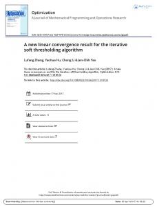
Figure 1 System overview. The lab based multi-joint actuation platform is shown on the left. Two sets of Bowden cables are connected to the exosuit to provide hip extension assistance while walking.
A variety of control approaches have been adopted by preexisting hip assistive devices. Some groups [23, 35, 37] including ours [25, 27-30] have utilized foot switches or sensorized insoles to detect foot contact events and then estimate the onset of assistance based on timing and assumptions from the known biomechanics of walking. Other approaches have involved the use of adaptive oscillators to extract the features of the hip joint angle alone [13, 38, 39], or in combination with electromyographic signals [40] to estimate user’s intended movement. In an effort to deliver appropriately-timed assistance at the hip, we developed an IMU-based iterative controller that accurately initializes the assistance at the onset timing of maximum hip flexion, which can vary from step to step. It also controls the timing of peak delivered force at a constant gait percentage after the onset timing for each step. With this controller, we can robustly evaluate the effects of different hip extension profiles in our future studies. In the following sections, we present an overview of the system and of the model used to determine how to appropriately apply the desired assistive forces to the body through a soft exosuit. In addition, we describe the gait event detection algorithm and the rationale of the iterative controller that adjusts timing and magnitude of assistance on a step-by-step basis to deliver a desired force profile to the wearer. Lastly, we present a preliminary evaluation of the force tracking performance of the controller and measure the effect on metabolic cost by means of a human subject study. II. SYSTEM OVERVIEW Our system includes a monoarticular hip exosuit and a reconfigurable multi-joint actuation platform previously described in [25, 26, 28-30]. The textile components of the hip exosuit (gray pieces in Figure 1) consist of a waist belt, two thigh braces, two IMU braces (elastic bands with a pocket in front of the leg for IMU placement) and two elastic straps on the lateral side of the leg, designed to hold the lower thigh brace from dropping. The multi-joint platform is a tethered system based on a modular design to enable rapid experimentation of different suit architectures, control strategies and human biomechanics. It consists of three modules, each composed of two linear actuators, which are designed to provide biologically inspired torques to multiple joints through Bowden cables individually or simultaneously [25]. In the present study, two degrees of freedom (DOF) of this platform were used to actuate hip extension on both legs. Each DOF consists of a geared DC motor that drives a ball screw in order to provide linear movement of a carriage. The transmission is based on Bowden cables; the sheath covering the inner cable is fixed to the actuator frame and the inner cable is connected to the actuation carriage on the ball screw. The actuator moves the carriage back and forth to either generate tension forces in the exosuit (pulling the cable) or to become fully transparent (feeding out cable so it becomes slack). The multi-joint platform includes motor controllers, data acquisition boards, power supply and a target PC to collect the sensor data and to control the actuators.
belt and inner cable connected to the top center of the thigh brace on the back of the leg as shown in Figure 2. By pulling the cable, the actuation platform shortens the distance between the two attachment points and delivers a controlled force in parallel to the wearer’s hip extension muscle group thus generating an assistive torque around the hip joint. III. MODEL AND SIMULATION OF SUIT-HUMAN SYSTEM In order to generate effective assistive profiles and understand how forces are generated through the exosuit, a simple model of the suit-human interface was developed. This model enables the required actuator profile to be determined for a desired hip assistive force during walking. The model takes account of information related to the suit-human stiffness, body geometry and hip angle profile during walking and then uses an estimate of the hip angle and specific desired force as the inputs to calculate the required actuator (and thus Bowden cable) position profile. A. System Modeling A diagram showing the main components of the hip exosuit (gray pieces) on two different gait postures of the right leg is presented in Figure 2. The Bowden cable sheath (thick black line) and the inner cable (thinner white line) connect the waist belt and the thigh brace. Under the application of an external force, the soft tissue beneath the fabric compresses. The amount of deformation of the soft tissue and the textile components is dependent on the stiffness of the textile and on the underlying soft tissue. The suit-human stiffness is one deciding factor of system efficiency, maximum actuator speed and system actuator profile [42, 43]. In our model, we calculate the deformation of the waist belt and thigh brace separately to generate a clearer model of how the exosuit deforms. The combined stiffness of the waist part and the thigh part is defined as 𝑘𝑤𝑎𝑖𝑠𝑡 and 𝑘𝑡ℎ𝑖𝑔ℎ , respectively. The stiffness value of the Bowden cable can be considered negligible for this model since it is almost inextensible compared to the soft tissue and the textile components [43]. A simple geometric model of the wearer’s leg including the cable attachment point is shown on the right of Figure 2. The initial angle (𝛼) formed by the hip joint center and the two attachment points of the cable is used to calculate the initial length of the inner cable (𝑥𝑙0 ) with the distance between the
The multi-joint actuation platform is connected to the soft exosuit with two Bowden cables, one for each leg. The Bowden cable sheath is connected to the bottom of the waist 3502
Figure 2 Left, the diagram of a person wearing the hip extension exosuit, showing two different postures of the right leg. Right, a simplified spring model of the human-exosuit interface.
hip joint center and the cable attachment point on the waist belt (𝑎) and the distance between hip joint center and the cable attachment point on the thigh brace (𝑙). 𝜃ℎ𝑖𝑝 is the hip joint angle during walking with respect to vertical. Hip flexion is denoted as a positive value. The length of the inner cable (𝑥𝑙 ) during walking can be calculated as a function of 𝜃ℎ𝑖𝑝 . Thus, knowing the desired force 𝐹, the deformation occurring on the waist belt (𝑥𝑤 ) and on the thigh brace (𝑥𝑡 ) can be calculated dividing 𝐹 by 𝑘𝑤𝑎𝑖𝑠𝑡 and 𝑘𝑡ℎ𝑖𝑔ℎ respectively. When there is no tension on the cable, the deformation of the waist belt (𝑥𝑤 ) and thigh brace (𝑥𝑡 ) should be zero. The actuator position, which is the required cable length pulled by the actuator (𝑥𝑐 ), is given by equation (1). It is the sum of the length caused by the deformation of the waist belt (𝑥𝑤 ), the thigh brace (𝑥𝑡 ) and the change of the cable length (𝑥𝑙 − 𝑥𝑙0 ) due to the thigh motion. 𝑥𝑐 = 𝑥𝑤 + 𝑥𝑡 + 𝑥𝑙 − 𝑥𝑙0
Where 𝑥𝑙 can be calculated as follows: 𝑥𝑙 = √𝑎2 + 𝑙 2 + 2𝑎𝑙𝑐𝑜𝑠(𝛼 + 𝜃ℎ𝑖𝑝 )
Thus, 𝑥𝑙 is a function of 𝜃ℎ𝑖𝑝 , and when 𝜃ℎ𝑖𝑝 = 0, 𝑥𝑙 = 𝑥𝑙0 . To calculate 𝑥𝑤 and 𝑥𝑡 at a specific force F, it is necessary to know 𝑘𝑤𝑎𝑖𝑠𝑡 and 𝑘𝑡ℎ𝑖𝑔ℎ . Experiments described later in Section B show that both these stiffness components can be approximated by a first order equation with coefficients 𝑝1 , 𝑝2 , 𝑝3 and 𝑝4 . 𝑘𝑤𝑎𝑖𝑠𝑡 = 𝑝1 𝑥𝑤 + 𝑝2
𝑘𝑡ℎ𝑖𝑔ℎ = 𝑝3 𝑥𝑡 + 𝑝4
Thus, 𝐹 = 𝑘𝑤𝑎𝑖𝑠𝑡 ∙ 𝑥𝑤 = 𝑝1 𝑥𝑤 2 + 𝑝2 𝑥𝑤 = 𝑘𝑡ℎ𝑖𝑔ℎ ∙ 𝑥𝑡 = 𝑝3 𝑥𝑡 2 + 𝑝4 𝑥𝑡
𝑥𝑤 =
−𝑝2 𝑝2 2 𝑝2 𝐹 + √( ) + 2𝑝1 2𝑝1 𝑝1
𝑥𝑡 =
−𝑝4 𝑝4 2 𝑝4 𝐹 + √( ) + 2𝑝3 2𝑝3 𝑝3
Lastly, substituting equations (2), (6) and (7) into equation (1) we obtain:
+ √(
−𝑝2 𝑝2 2 𝑝2 𝐹 −𝑝4 + √( ) + + 2𝑝1 2𝑝1 𝑝1 2𝑝3
and 𝑘𝑡ℎ𝑖𝑔ℎ , geometry of the subject’s body (𝑙, 𝑎) and hip angle (𝜃ℎ𝑖𝑝 ). Thus, with those values as inputs, this model provides a correct pattern of the actuator profile but inaccurate offset and magnitude for different individuals, which is why we introduce an iterative controller to adjust the offset and magnitude on a step-by-step basis, according to the real-time measurement of the wearer’s kinematics and delivered assistive force. B. Measurement of Suit-human Stiffness A set of experiments were performed using the actuation unit from the multi-joint platform to determine the value of the combined stiffness of 𝑘𝑤𝑎𝑖𝑠𝑡 and 𝑘𝑡ℎ𝑖𝑔ℎ . This and the other human subject studies presented in this study were approved by the Harvard Medical School Committee on Human Studies. To obtain an estimate of the combined suit-human stiffness, one subject stood with his feet 50 cm apart in a pose close to that at 13% GC, which is close to when force was maximally applied to hip extension in our previous work [29, 30]. One end of the Bowden cable sheath was connected to a rigid aluminum frame placed behind the subject and the inner cable was connected to the attachment points on waist belt or on front leg thigh brace alternately [43], as shown in Figure 3. Stiffness was assumed to be the same across legs. In each of the two trials, the actuator was commanded to pull the cable by 72 mm at a constant speed of 0.029 m/s and then to release the cable with the same speed. The cable displacement was determined experimentally so that a consistent peak force of approximately 300 N and 200 N was applied to the wearer on the waist and on the thigh, respectively. Three cycles of cable pulling and releasing are plotted on the left side of Figure 3, with an offset removed where no force was applied to the body. The calculated stiffness of 𝑘𝑤𝑎𝑖𝑠𝑡 and 𝑘𝑡ℎ𝑖𝑔ℎ , shown as the solid blue and red line in Figure 3, are curves fitted to average of the rising and falling portions of the curve, where the coefficients in equation (5) were:
𝑥𝑐 = √𝑎2 + 𝑙 2 + 2𝑎𝑙cos(𝛼 + 𝜃ℎ𝑖𝑝 ) +
Figure 3 Measured stiffness of the human-exosuit interface. Left, measured and modeled stiffness of thigh and waist. Right, the experimental setup for stiffness testing
(8)
𝑝1 = 50400; 𝑝2 = 828; 𝑝3 = 69200; 𝑝4 = 2319;
𝑝4 2 𝑝4 𝐹 ) + − √𝑎2 + 𝑙 2 + 2𝑎𝑙cos𝛼 − 𝑥𝑙0 2𝑝3 𝑝3
From these equations, it can be seen that the calculated actuator profile depends on the combined stiffness of 𝑘𝑤𝑎𝑖𝑠𝑡
where 𝑥𝑤 , 𝑥𝑡 are in meters and 𝑘𝑤𝑎𝑖𝑠𝑡 , 𝑘𝑡ℎ𝑖𝑔ℎ in Newton per meter. These average values are used for the simulation results we present below. It is worth noting that the variability of suithuman stiffness among different wearers would slightly change the magnitude of the deformation at the waist and thigh (dashed green and red line in Figure 4 (b)); however, the
3503
the actuator should follow 𝑥𝑐 (dashed blue line) in Figure 4(b), which is the sum of 𝑥𝑙 − 𝑥𝑙0 , 𝑥𝑤 and 𝑥𝑡 . It is worth noting that the minimum value of 𝑥𝑐 equals zero due to the fact that we assumed there is no slack on the cable in this model. In these calculations, we use 𝑎 = 0.16 m, 𝑙 = 0.26m, which are average values measured in eight subjects from our human subject study. The desired force 𝐹 and the simulated actuator profile (𝑥𝑐 ) are plotted in Figure 4(c). Some modifications were applied to this profile to simplify the control algorithm, yet to have it still closely match 𝑥𝑐 . We modified the curve to have flat line from 45%–90% GC to maintain the cable slack ensuring no force during swing phase. To have a profile that can be defined clearly by the timing and also closely fit 𝑥𝑐 from 0–45% GC and 90–100% GC, we found a trapezoidal profile by visual inspection. Thus, we replaced complex actuator profile 𝑥𝑐 with a simple trapezoidal profile whose timing and magnitude can be easily modulated by the iterative controller on a step-bystep basis. IV. ITERATIVE CONTROLLER The considerable variability in hip kinetics and kinematics across subjects makes the task of applying constant and repetitive assistive forces particularly challenging. Moreover, possible textile component migration over an extended period of walking add the difficulties to a robust force performance. This section describes our approach to the design of a controller to self-adjust and compensate for these variabilities by adapting the timing and the magnitude of the calculated actuator profile pattern on a step by step basis. Figure 4 (a), desired force delivers around 30% of the hip extension power. The average biological hip power is from our internal speed load study. (b), displacement of waist belt (𝑥𝑤 ) , thigh brace (𝑥𝑡 ) , and motions of the attachment point due to the leg motion (𝑥𝑙 − 𝑥𝑙0 ) result in the simulated actuator profile (𝑥𝑐 ). (c), the simulated actuator profile can be simplified into a trapezoidal profile. MHF is the onset timing of maximum hip flexion.
variations are expected to be small based on past work [43] and the control function we describe is not sensitive to variations in these parameter values. C. Simulation Our desired force profile is inspired by the biological hip torque and consists of a scaled and shifted sinusoid for a portion of the GC starting from just before heel strike. This exosuit is intended to provide a joint torque equivalent to approximately 30% of the biological hip extension moment. The force profile ramps up slightly before heel strike (~90% of the GC) to assist the hip extensors developing the initial contact at the end of swing phase. The force peaks at 200 N around 13% GC, which is close to the peak of hip joint power [44, 45]. The desired force profile, average hip joint power and the simulated delivered power to the joint are plotted in Figure 4(a). The calculated actuator profile (𝑥𝑐 ) together with the different components described in the equation (1), are shown in Figure 4(b). If the motor were to perfectly track the given hip motion and apply no force to the exosuit, then the actuator profile would follow the profile of 𝑥𝑙 − 𝑥𝑙0 (black line). When applying the desired force (red line in Figure 4(a)) to the suit,
A. Gait Event Estimation Using IMU The inter-subject variability of hip kinetics appears evident in a sample of data of three subjects from an internal study from our group as shown in Figure 5. These sample data show that the starting point of hip extension positive power during the swing phase (shown with a dashed blue vertical line) can vary widely between different subjects. This large variability introduced the need to determine the onset of the applied assistance to be concurrent with the onset timing of hip positive power rather than estimated based on the timing between heel strikes. From a biomechanical point of view, hip extensor muscles start to activate slightly before the maximum hip flexion angle [44, 45]. In an examination of kinetic and kinematic data from a previous internal study, it can be also seen that the timing of maximum hip flexion is close to the onset timing of gluteus maximus activation (black line in Figure 5). Moreover, it is known that the timing of maximum hip flexion is coincident with the starting point of the positive hip extension power (red line in Figure 5), as this is the when the hip changes its direction of motion from flexion to extension. Following this rationale, we decided to use the timing of maximum hip flexion angle as a suitable gait event to determine the onset timing of the hip extension assistance. To detect the maximum hip flexion angle for each leg, two IMUs (VectorNav Technologies, Dallas, Texas, US) were attached to the front of each thigh to measure the thigh angle in real time. Since the hip joint angle profile is close to the thigh angle profile [44], the maximum hip flexion angle can be
3504
Figure 6 Control diagram of the iterative hip extension controller
on the exosuit [45, 46]. Recording these parameters across each GC allowed an automatic adjustment of the actuator position profile xc, in order to keep the desired force profile consistent over time and between users. If the peak force or the pretension force were lower than desired value during a GC, the maximum amplitude or the offset of the position profile would be raised so that the forces increase in the next step, or vice versa. To prevent disruptions caused by an incidental change between consecutive steps, the maximum correction of actuator cable position per step was limited to 2 mm, ensuring a smooth transition between consecutive steps. By having the controller continuously correcting the actuator position profile, the desired force can be achieved without requiring a perfect initial trapezoidal profile. The overall diagram of the controller is shown in Figure 6.
Figure 5 Sample data of average hip angle, thigh angle, hip power and scaled EMG of Gluteus Maximus of one subject in each diagram from our internal speed load study. The positive values are hip flexion, thigh flexion, hip extension power with respect to hip angle, thigh angle, and hip power. The dashed blue vertical line indicates the time of maximum hip flexion marked as MHF.
estimated from the maximum thigh angle measured from the IMU. A gait detection algorithm was then designed to segment the stride using the onset timing of maximum hip flexion. The algorithm identifies the first positive thigh angle peak (corresponding to maximum hip flexion angle) after a negative thigh angle peak (corresponding to maximum hip extension angle) as the maximum hip flexion point. The algorithm considers only local peaks in positive thigh angle (meaning hip flexion) that immediately follow local minima in negative thigh angle (meaning hip extension). The stride time is measured by the controller as the time between two consecutive maximum hip flexion events. The expected duration of the current stride time (EST) is estimated from the average of the previous two strides. This estimation method for EST is only valid for lab-based tests on a treadmill, where stride time variability is low. More dynamic conditions, such as outdoor walking may require an alternative approach. It is worth noting that the GC used in all figures is defined by heel strikes detected by the force plate of our treadmill in our post processing. B. Iterative Profile Generation Based on the simulation model and the gait detection method, a desired force can be generated on the cable by having the actuator follow the scaled version of the trapezoidal profile described above. To ensure a consistent force delivered to the user given variability in their gait and exosuit positioning and alignment, two load cells (LSB200, Futek Advanced Sensor, USA) were placed in series with the Bowden cable to monitor key features of the external assistance, such as peak force amplitude and timing and pretension force at the timing of maximum hip flexion angle
The simplicity and the reliability of this control structure allowed us to easily design and implement different timing and magnitude of force profiles, to quickly test their effect on human locomotion. For the preliminary human subject testing presented in this paper, the initial pattern of the actuator profile begins ramping up at the detection of maximum hip flexion angle timing, which can vary from step to step and across subjects. The actuator profile continues to ramp for the next 18% EST, and holds its peak value for the following 11% EST. The actuator then decreases back to original position over the next 26% EST, as shown in solid blue line in Figure 4(c). The controller iteratively adjusts the trapezoidal profile’s initial position and peak magnitude to achieve the desired force profile. V. EXPERIMENTAL PROTOCOL To evaluate the performance of the iterative hip controller and assess its effect on metabolic reduction during loaded walking, we conducted an experimental protocol on eight healthy subjects (age 29.8 ± 5 y.o., weight 82.6 ± 5.8 kg, height 179.1 ± 5.0 cm) walking on an instrumented treadmill (Bertec, Columbus, Ohio, US) at a speed of 1.5 m/s while carrying a 23 kg weighted backpack. The controller was evaluated by comparing the desired force profile described in the model and simulation with the corresponding delivered force measured experimentally. Metabolic effect was evaluated for four different force profiles with the same peak force magnitude but different timings (A: onset ~90% GC and peak 13% GC; B: onset ~90% GC and peak 17% GC; C: onset ~0% GC and peak 13% GC; D: onset ~0% GC and peak 17% GC). Consent was obtained from experimental participants after the nature and possible consequences of the exosuit studies were explained. The experimental protocol was split into a training day and a testing day, during which we collected data. On the training
3505
TABLE 1 PEAK FORCE AND PEAK TIMING ACROSS FOR TEN MEASURED STEPS FOR EACH SUBJECT IN THE HUMAN SUBJECT TEST. PEAK TIMING IS THE RATIO OF THE DURATION BETWEEN THE MOMENT OF THE ONSET TIMING OF MAXIUM HIP FLEXION AND THE MOMENT OF REACHING THE PEAK FORCE TO AVERAGE STRIDE TIME. THE TARGET PEAK FORCE AND PEAK TIMING ARE 200 N AND 23% SHOWN IN OUR SIMULATION. Subject
1
2
3
4
5
6
7
8
Ave
Average Peak Force (N)
200.5
198.7
200.5
195.7
198.1
198.0
197.3
196.4
198.2 ±1.6
Average Peak Timing (%)
23.2
22.9
22.5
23.1
22.3
23.6
23.0
21.5
22.7 ±0.6
day, subjects were fitted with the exosuit and walked for eight randomized six-minute bouts, experiencing each of the four different powered conditions twice, in order to get familiar with the functioning of the system. During the testing day, subjects underwent five different six-minute data collection bouts: the four powered conditions and the one unpowered condition, after a four-minute warm-up. All the conditions were randomized to cancel the effect of adaptation and fatigue. Carbon dioxide production and oxygen consumption rate during walking were assessed by means of indirect calorimetry using a portable gas analysis system (K4b2, Cosmed, Roma, Italy). They were averaged across the last two minutes of each walking condition and then used to calculate metabolic power using a modified Brockway equation [48]. Net metabolic power was obtained by subtracting the metabolic power obtained during a standing trial performed at beginning of the collection session from the metabolic power calculated during the walking conditions. VI. RESULTS A. Assistive Force Performance Peak force timing and magnitude are fundamental parameters in the design of an effective force profile [46, 47],
thus those are used as our measurement matrix of the controller performance. Figure 7 shows the desired force described in the model and simulation as dashed red lines and the measured average delivered force of ten steps from each of the eight subjects in powered condition A as solid blue lines. The peaks of the force profiles are marked with red circles and blue diamonds, and the values of peak force and peak force timing for each subject are presented in Table 1. From Figure 7, it can be seen that the onset timing varies across individuals as is expected given the variability in the hip kinematics and kinetics across subjects that was previously described. This illustrates the benefit of our IMU-based detection of a gait event that is coincident with the onset timing of the desired assistance. Additionally, the measured peak force amplitude was only ~1% less on average (198N vs 200N) than the desired force demonstrating the ability to accurately command a desired force with this control approach. The small difference was likely due to the insufficient tracking of the position controller, which created a small following position error of the commanded actuator profile. The observed small force between mid-stance and terminal-swing was likely caused by the passive interaction between the load cell and the exosuit, as opposed to an active pulling force on the leg from
Figure 7 Desired force (dashed red line) and measured force (solid blue line) with standard deviation (blue shade) recorded by the load cell for ten steps from all eight subjects. The onset timing shown in red is the moment of maximum hip flexion estimated from the IMU placed on the thigh. 3506
the actuator. Finally, the results also showed that we could accurately control the timing of the peak force as we found the average force reached the peak at 22.7 ±0.6% GC after onset timing, as compared to the desired value of 23%. This result demonstrates that our system can robustly deliver a force profile that shifts with the timing of the maximum hip flexion. The characteristics of this controller guarantee its benefits can be achieved from the same effective assistive force to all wearers, which provides us a robust system to explore the effects of different assistive profiles of hip extension. B. Metabolic Reduction External actuation resulted in a lower metabolic power required to walk at 1.5 m/s with a 23 kg load. On average, the exosuit reduced the metabolic cost of walking ranging from 28.04 ± 7.4 W to 41.1 ± 4.1 W, representing net metabolic reductions for each condition tested (A: 5.7% ± 1.5%; B: 8.5 ±0.9%; C: 6.3 ±1.4%; D: 7.1 ±1.9%). This metabolic result is calculated from the metabolic results of six out of eight subjects due to malfunctions in the portable pulmonary gas exchange measurement device during the test. Mean and standard error reported for metabolic data.
would also like to thank Copley Controls Corporation for providing Accelnet motor controllers. REFERENCES [1] [2]
[3]
[4]
[5]
[6]
VII. CONCLUSION AND FUTURE WORK We have presented the design of an IMU-based iterative hip controller that can deliver a pre-defined assistive profile to assist hip extension. The controller was implemented on a mono-articular soft exosuit coupled to a lab-based multi-joint actuation platform that enables rapid reconfiguration of different sensors and control strategy implementation. The controller performance and the effect on metabolic power were evaluated by means of an experimental protocol with eight human subjects. Results showed that assistance could be delivered reliably across subjects. Specifically, for a given profile, delivered force started concurrently with the timing of the maximum hip flexion angle and reached its peak timing 22.7 ±0.63% later in the gait cycle (desired 23%) with a peak magnitude of 198.2 ± 1.6 N (desired 200 N), equivalent to an average peak torque of 30.5 ± 4.7 Nm. The control approach was used to assess the metabolic effect of four different force profiles with two different onset timings and two different peak force timings. Metabolic reductions ranging from 5.7% to 8.5% were found when comparing the powered conditions with the unpowered condition. The results demonstrate that this approach is suitable for controlling hip extension assistance profiles across different subjects. This enables future studies to assess the biomechanical and physiological responses to different assistance profiles to determine the optimal hip extension assistance during walking. Ultimately, we expect these treadmill based studies with a tethered soft exosuit to inform the development of future autonomous soft exosuits for assisting the hip that will improve the walking efficiency of load carriers.
[7]
[8]
[9]
[10]
[11]
[12]
[13]
[14]
[15]
ACKNOWLEDGMENT The authors would like to thank Stephen Allen, Alan Asbeck, Brendan Quinlivan, Fabricio Saucedo and Diana Wagner for their contributions to this project. The authors
[16]
3507
H. Kazerooni, “The Berkeley lower extremity exoskeleton project,” Springer Tracts Adv. Robot., vol. 21, pp. 291–301, 2006. C. J. Walsh, K. Endo, and H. Herr, “a Quasi-Passive Leg Exoskeleton for Load-Carrying Augmentation,” Int. J. Humanoid Robot., vol. 4, pp. 487–506, 2007. W. Kim, S. Lee, H. Lee, S. Yu, J. Han, and C. Han, “Development of the heavy load transferring task oriented exoskeleton adapted by lower extremity using qausi - Active joints,” 2009 Iccas-Sice, pp. 1353–1358, 2009. A. Esquenazi, M. Talaty, A. Packel, and M. Saulino, “The ReWalk powered exoskeleton to restore ambulatory function to individuals with thoracic-level motor-complete spinal cord injury,” Am. J. Phys. Med. Rehabil., vol. 91, pp. 911–921, 2012. P. D. Neuhaus, J. H. Noorden, T. J. Craig, T. Torres, J. Kirschbaum, and J. E. Pratt, “Design and evaluation of Mina: A robotic orthosis for paraplegics,” IEEE Int. Conf. Rehabil. Robot., 2011. H. Yano, S. Kaneko, K. Nakazawa, S. I. Yamamoto, and A. Bettoh, “A new concept of dynamic orthosis for paraplegia: the weight bearing control (WBC) orthosis.,” Prosthet. Orthot. Int., vol. 21, pp. 222–228, 1997. B. J. Ruthenberg, N. A. Wasylewski, and J. E. Beard, “An experimental device for investigating the force and power requirements of a powered gait orthosis,” J. Rehabil. Res. Dev., vol. 34, pp. 203–213, 1997. Y. Ohta, H. Yano, R. Suzuki, M. Yoshida, N. Kawashima, and K. Nakazawa, “A two-degree-of-freedom motor-powered gait orthosis for spinal cord injury patients,” Proc. Inst. Mech. Eng. H., vol. 221, pp. 629–639, 2007. H. Kawamoto, T. Hayashi, T. Sakurai, K. Eguchi, and Y. Sankai, “Development of single leg version of HAL for hemiplegia,” in Proceedings of the 31st Annual International Conference of the IEEE Engineering in Medicine and Biology Society: Engineering the Future of Biomedicine, EMBC , vol. 2009, pp. 5038–5043, 2009. D. Zanotto, P. Stegall, and S. Agrawal, “ALEX III: A novel robotic platform for gait training - design of the 4-DOF Leg,” in IEEE Intl. Conference on Robotics and Automation, pp. 3914–3919, 2013. J. F. Veneman, R. Kruidhof, E. E. G. Hekman, R. Ekkelenkamp, E. H. F. Van Asseldonk, and H. Van Der Kooij, “Design and evaluation of the LOPES exoskeleton robot for interactive gait rehabilitation,” IEEE Trans. Neural Syst. Rehabil. Eng., vol. 15, pp. 379–386, 2007. H. A. Quintero, R. J. Farris, and M. Goldfarb, “A method for the autonomous control of lower limb exoskeletons for persons with paraplegia,” J. Med. Device., vol. 6, p. 041003, 2012. F. Giovacchini, F. Vannetti, M. Fantozzi, M. Cempini, M. Cortese, A. Parri, T. Yan, D. Lefeber, and N. Vitiello, “A light-weight active orthosis for hip movement assistance,” Rob. Auton. Syst., vol 73, pp. 123-134, 2015. B. G. Do Nascimento, C. B. S. Vimieiro, D. A. P. Nagem, and M. Pinotti, “Hip orthosis powered by pneumatic artificial muscle: Voluntary activation in absence of myoelectrical signal,” Artif. Organs, vol. 32, pp. 317–322, 2008. C. Buesing, G. Fisch, M. O’Donnell, I. Shahidi, L. Thomas, C. K. Mummidisetty, K. J. Williams, H. Takahashi, W. Z. Rymer, and A. Jayaraman, “Effects of a wearable exoskeleton stride management assist system (SMA®) on spatiotemporal gait characteristics in individuals after stroke: a randomized controlled trial,” J. Neuroeng. Rehabil., vol. 12, no. 1, p. 69, 2015. Q. Wu, X. Wang, F. Du, and X. Zhang, “Design and control of a
[17]
[18]
[19]
[20]
[21]
[22]
[23]
[24]
[25]
[26]
[27] [28]
[29]
[30]
[31]
[32] [33]
[34]
[35]
powered hip exoskeleton for walking assistance,” Int. J. Adv. Robot. Syst., p. 1, 2015. J. E. Pratt, B. T. Krupp, C. J. Morse, and S. H. Collins, “The RoboKnee: an exoskeleton for enhancing strength and endurance during walking,” in IEEE International Conference on Robotics and Automation, vol. 3, pp. 2430–2435, 2004. A. M. Grabowski and H. M. Herr, “Leg exoskeleton reduces the metabolic cost of human hopping.,” J. Appl. Physiol., vol. 107, pp. 670–678, 2009. L. M. Mooney, E. J. Rouse, and H. M. Herr, “Autonomous exoskeleton reduces metabolic cost of human walking during load carriage.,” J. Neuroeng. Rehabil., vol. 11, p. 80, 2014. P. Malcolm, W. Derave, S. Galle, and D. De Clercq, “A simple exoskeleton that assists plantarflexion can reduce the metabolic cost of human walking,” PLoS One, vol. 8, p. e56137, 2013. G. S. Sawicki and D. P. Ferris, “Powered ankle exoskeletons reveal the metabolic cost of plantar flexor mechanical work during walking with longer steps at constant step frequency.,” J. Exp. Biol., vol. 212, pp. 21–31, 2009. S. H. Collins, M. B. Wiggin, and G. S. Sawicki, “Reducing the energy cost of human walking using an unpowered exoskeleton,” Nature., vol. 522, pp. 212-215, 2015. C. L. Lewis and D. P. Ferris, “Invariant hip moment pattern while walking with a robotic hip exoskeleton,” J. Biomech., vol. 44, pp. 789– 793, 2011. M. Wehner, B. Quinlivan, P. M. Aubin, E. Martinez-Villalpando, M. Baumann, L. Stirling, K. Holt, R. Wood, and C. Walsh, “A lightweight soft exosuit for gait assistance,” Proc. - IEEE Int. Conf. Robot. Autom., pp. 3362–3369, 2013. Y. Ding, I. Galiana, A. Asbeck, B. Quinlivan, S. M. M. De Rossi, and C. Walsh, “Multi-joint actuation platform for lower extremity soft exosuits,” in Robotics and Automation (ICRA), pp. 1327–1334, 2014. A. T. Asbeck, S. M. M. De Rossi, I. Galiana, Y. Ding, and C. Walsh, “Stronger, Smarter, Softer,” Robot. Autom. Mag. IEEE, vol. 21, pp. 22–33, 2014. A. T. Asbeck, K. Schmidt, and C. J. Walsh, “Soft Exosuit for Hip Assistance,” Rob. Auton. Syst., in press. F. Panizzolo, I. Galiana, A. T. Asbeck, C. Siviy, K. Schmidt, K. G. Holt, and C. J. Walsh, “A biologically-inspired multi-joint soft exosuit that can reduce the energy cost of loaded walking,” J. Neuroeng. Rehabil., in review. Y. Ding, I. Galiana, A. T. Asbeck, S. Marco, M. De Rossi, J. Bae, R. T. Santos, V. L. Araujo, S. Lee, K. G. Holt, and C. Walsh, “Biomechanical and physiological evaluation of multi-joint assistance with soft exosuits,” IEEE Trans. Neural Rehabil. Syst. Eng., in press. A. T. Asbeck, K. Schmidt, I. Galiana, and C. J. Walsh, “Multi-joint soft exosuit for gait assistance,” in Robotics and Automation (ICRA), pp. 6197-6204, 2015. D. J. Farris and G. S. Sawicki, “The mechanics and energetics of human walking and running: a joint level perspective,” J. R. Soc. Interface, vol. 9, pp. 110–118, 2012. T. M. Owings and M. D. Grabiner, “Variability of step kinematics in young and older adults,” Gait Posture, vol. 20, pp. 26–29, 2004. M. M. Samson, A. Crowe, P. L. de Vreede, J. A. Dessens, S. A. Duursma, and H. J. Verhaar, “Differences in gait parameters at a preferred walking speed in healthy subjects due to age, height and body weight.,” Aging Clin. Exp. Res., vol. 13, pp. 16–21, 2001. D. A. Winter, “Kinematic and kinetic patterns in human gait: Variability and compensating effects,” Hum. Mov. Sci., vol. 3, pp. 51– 76, 1984. T. Lenzi, M. C. Carrozza, and S. K. Agrawal, “Powered hip exoskeletons can reduce the user’s hip and ankle muscle activations
[36]
[37]
[38]
[39]
[40]
[41]
[42]
[43]
[44] [45] [46]
[47]
[48]
3508
during walking,” IEEE Trans. Neural Syst. Rehabil. Eng., vol. 21, pp. 938–948, 2013. R. Kitatani, K. Ohata, H. Takahashi, S. Shibuta, Y. Hashiguchi, N. Yamakami. “Reduction in energy expenditure during walking using an automated stride assistance device in healthy young adults,” Arch. Phys. Med. Rehabil., vol. 95, no. 11, pp. 2128–33, 2014. K. N. Winfree, P. Stegall, and S. K. Agrawal, “Design of a minimally constraining, passively supported gait training exoskeleton: ALEX II,” in IEEE International Conference on Rehabilitation Robotics, pp. 1–5, 2011. R. Ronsse, T. Lenzi, N. Vitiello, B. Koopman, E. Van Asseldonk, S. M. M. De Rossi, J. Van Den Kieboom, H. Van Der Kooij, M. C. Carrozza, and A. J. Ijspeert, “Oscillator-based assistance of cyclical movements: Model-based and model-free approaches,” Med. Biol. Eng. Comput., vol. 49, pp. 1173–1185, 2011. K. Seo, S. Hyung, B. Kwon, C. Younbaek, and L. Youngbo, “A new adaptive frequency oscillator for gait assistance,” in IEEE Intl. Conference on Robotics and Automation, pp. 5565–5571, 2015. G. Aguirre-Ollinger, “Learning muscle activation patterns via nonlinear oscillators: Application to lower-limb assistance,” in IEEE International Conference on Intelligent Robots and Systems, pp. 1182– 1189, 2013. A. M. Dollar and H. Herr, “Lower extremity exoskeletons and active orthoses: Challenges and state-of-the-art,” IEEE Transactions on Robotics, vol. 24, pp. 144–158, 2008. A. T. Asbeck, S. M. M. Derossi, K. G. Holt, and C. J. Walsh, “A Biologically inspired soft exosuit for walking assistance,” Int. J. Rob. Res., 0278364914562476, 2015. B. Quinlivan, A. Asbeck, D. Wagner, T. Ranzani, S. Russo, and C. Walsh, “Force transfer characterization of a soft exosuit for gait assistance,” in International Design Engineering Technical Conferences & Computers and Information in Engineering Conference, pp. 1–8, 2015. J. Perry and J. M. Burnfield, “Gait Analysis: Normal and Pathological Function. Delmar Learning,” 1992. D. A. Winter, “Biomechanics and motor control of human movement,” 2005. J. Zhang, C. C. Cheah, and S. H. Collins, “Experimental comparison of torque control during human walking,” in IEEE International Conference on Robotics and Automation, pp. 5584-5589, 2015. S. Galle, P. Malcolm, S. H. Collins, J. Speeckaert, and D. De Clercq, “Optimizing robotic exoskeletons actuation based on human neuromechanics experiments: interaction of push-off timing and work,” in International Syposium on Adaptive Motion of Animals and Machines, pp. 1–3, 2015. J. M. Brockway, “Derivation of formulae used to calculate energy expenditure in man,” Human Nutrition: Clinical Nutrition, pp. 463– 471, 1987.