3D mapping of a search and rescue scenario using a light- weight and highly ..... partly due to the extra time consumed by saving data to the hard drive for.
IEEE TRANSACTION ON ROBOTICS AND AUTOMATION, VOL. X, NO. X, OCTOBER 2008
1
Information Efficient 3D Visual SLAM for Unstructured Domains Weizhen Zhou, Student Member, IEEE, Jaime Valls Mir´o and Gamini Dissanayake, Member, IEEE,
Abstract—This paper presents a novel vision-based sensory package and an information efficient simultaneous localization and mapping (SLAM) algorithm. Together, we offer a solution for building three-dimensional dense map in unknown and unstructured environment with minimal computational costs. The sensory package we adopt consists of a conventional camera and a range imager, which provide range and bearing and elevation inputs as commonly used by three-dimensional featurebased SLAM. In addition, we propose an algorithm to give the robots the ‘intelligence’ to select, out of the steadily collected data, the maximally informative observations to be used in the estimation process. We show that, although the actual evaluation of information gain for each frame introduces an additional computational cost, the overall efficiency is significantly increased by keeping the matrix compact. The noticeable advantage of this strategy is that the continuously gathered data is not heuristically segmented prior to being input to the filter. Quite the opposite, the scheme lends itself to be statistically optimal and is capable of handling large data sets collected at realistic sampling rates. Index Terms—Vision, SLAM, information form, delayed state formulation, urban search and rescue (USAR).
I. I NTRODUCTION
AND
R ELATED W ORK
NE of the many important applications of mobile robots is to reach and explore terrains which are inaccessible or considered dangerous to humans. Such environments are frequently encountered in search and rescue scenarios where prior knowledge of the environment is unknown but required before any rescue operation can be deployed. A small mobile robot equipped with an appropriate sensor package can possibly be regarded as the best aid in such scenario. The robot is expected to navigate itself through the site and generate maps of the environment which human rescuers can then use for navigating and locating victims. Despite the wealth of research in planar robot mapping, the limitations of traditional 2D feature maps in providing useful and understandable information in these scenarios have propelled increasing research efforts towards the generation of richer and more descriptive 3D maps instead. 3D mapping of a search and rescue scenario using a lightweight and highly mobile autonomous robot is a challenging predicament which can be framed within the generic simultaneous localization and mapping (SLAM) problem [1], where a robot is expected to move with six degrees-of-freedom in a three-dimensional environment. This demanding picture is further complicated by the lack of odometry information from the wheel encoders, as this tends to be totally unreliable due to
O
W. Zhou (corresponding author), J. Valls Mir´o and G. Dissanayake are with the ARC Centre of Excellence for Autonomous Systems, Australia, e-mail: {w.zhou, j.vallsmiro, g.dissanayake}@cas.edu.au. Manuscript received December 20, 2007; revised May 20, 2007.
the nature of the disaster environment. The emerging approach based on the ubiquitous laser range scanner lies in deriving odometry from 3D scan matching, possibly fusing textured images a-posteriori to recover the final shape [2]. When the noise on the relative locations is small, as is the case of accurate range sensor such as tilting laser range finders or other forms of egomotion sensors, such as large and expensive IMUs, a good quality estimate of the final 3D map can be expected if displacement between robot poses is limited. By doing so the SLAM problem is reduced to that of the estimation of a state vector containing all the camera/robot poses. This is the approach used by many researchers in the SLAM community, e.g. [3], [12], [10]. Further exploitation of appearance sensors, capable of providing scene texture information to the rescuer as well as salient visual features for “place recognition” in the estimation process itself, is becoming more prominent as they provide useful and understandable information which humans can then use for navigating and locating victims in rescue scenarios. The use of a stereo camera rig for 3D mapping is advantageous as that makes the system fully observable in that the sensor provides enough information (range, bearing and elevation) to compute the full three-dimensional state of the observed landmarks. Some approaches rely on 2D projections of the features, such as the vertical edges corresponding to corners and door frames as proposed in [15], which are subsequently tracked using an Extended Kalman Filter (EKF). This type of visual feature representation is not sufficiently distinctive and elaborate data association solutions are required to reject spurious matches. [16], [22] have made use of a Triclops system where three images are obtained at each frame. SIFT features are detected, matched and used in an EKF. The approach was however not globally consistent as the cross-correlations were not fully maintained for computational reasons. [20] proposed a Rao-Blackwellised particle filter instead. A motion model based purely on visual odometry was used, effectively generalising the problem to unconstrained 3D motion. Feature management and computational complexity, which grow exponentially with the number of particles, is likely to make this strategy infeasible in a large environment. Other approaches rely on iterative minimization algorithms from vision techniques such as Iterative Closest Point (ICP) to perform local 3D alignments to solve the SLAM problem [18], which produce good results when restricted to fairly structured environments and limited egomotion dynamics. Similar limitations are reported in [21], where 3D line segments became landmarks suitable to be used in a particle filter implementation in which each particle also carried with it
IEEE TRANSACTION ON ROBOTICS AND AUTOMATION, VOL. X, NO. X, OCTOBER 2008
an EKF. Although these are promising approaches to solve the SLAM problem using visual cues, camera calibration and stereo correlation are still arbitrarily fickle. But more relevant to the harsh conditions encountered in search and rescue scenarios, determining correspondences between pixels in stereo pairs is a slow process that strongly depends on accommodating surfaces for the presence of texture, as well as the particular ambient lighting conditions [26]. Recently, more research effort has been directed towards the idea of fusing visual and range sensorial data to obtain dense 3D maps. For example a rotating laser scanner was employed in [2] to generate an initial rough 3D map using ICP registrations, improved with dense texture images to recover the final 3D shape. [24], [25] also made use of a tilting 2D laser scanner and a camera for SLAM in an outdoor environment, where the camera was mainly used in the detection of loop closure. In [6] our work was also focused on sequential 3D dense map reconstruction within a visual SLAM framework. The novelty was in the shape of a combined visual sensor package proposed to enhance the salient features and scene textures captured from a conventional passive camera, with the 3D data of the corresponding scene as provided by a low resolution range imager - successfully proved by [17] to have the ability to be used for some simple local navigation. The combined observations made by these two cameras were then used as the sole input to a conventional Extended Information Filter (EIF) based SLAM algorithm thereafter. The key idea is to use the traditional pin-hole camera image for textural 3D reconstruction and to help in the data association, and use a selection of the combined 3D features from the aggregated camera and range scans to update the filter. Once the accurate camera pose sequence (in the global frame) at which the scans were taken was available, the textured ranging images could be combined to produce the final 3D point cloud map. In the proposed technique the robot and feature poses needed to be recovered at the end of each ‘acquire, update’ cycle. However, the inversion of the information matrix evoked during each estimation cycle came at a significant computational cost. Although the sensor package was capable of delivering data at a frame rate of 5 to 10 Hz, which theoretically guaranteed in itself appropriate frame registration, the increasing sampling delay between consecutive frames caused by extensive computation could yield inadequate data association and therefore unsuccessful frame registration. Such problem is particularly magnified in unstructured environment where the robot’s sights change rapidly and unpredictably along its undulating path. Many efforts have been made in recent years to reduce the computational encumbrance generally faced by most SLAM algorithms, particularly in its most efficient information form. In related work [11], Eustice et al implemented an Exactly Sparse Delayed-State Filter (ESDSF) which maintained a sequence of delayed robot poses at places where low-overlap images were captured manually. In [12] a Delayed State Extended Kalman Filter was also used to fuse the data acquired with a 3D laser range finder. A segmentation algorithm was employed to separate the data stream into distinct point clouds based on orientation constraints, each referenced to a vehicle
2
position. Both implementations significantly reduced the computational cost by eliminating features from the state vector to achieve practical performance. However, one noticeable common problem of these strategies is that loop closure can not be automatically detected. Separate loop closure methods were required in conjunction with their proposed techniques, unlike the visual (and outlier removal) data association contemplated in [6]. Furthermore, both methods require either human supervision over the data acquisition process or raw odometry measurements to minimize the number of critical robot poses that should be maintained, none of which are available in the settings of a search and rescue scenario. An alternative strategy has recently been contemplated in [19] with a global batch rectification strategy that minimizes mutual information between images in order to achieve a manageable number of variables for the fusion process. The scheme essentially provides an efficient optimization solution at a claimed high action compression rate. However, the robot and feature uncertainty beliefs are not accounted for and actions can not be de-compressed when needed. II. T HE P ROPOSED M ETHODOLOGY While it has been demonstrated [6] that dense 3D maps can be constructed with carefully prepared data sets collected in a static fashion, in the sense that each camera pose needs to be manually situated to ensure extensive overlapping between consecutive frames as well as the full coverage of the arena, in real applications such as search and rescue it is unrealistic to expect such ‘ideal’ data sets. The sensor package is more likely to be operated at its maximum rate to overcome problems such as motion blurriness and drastic changes in the scene due to the inherent nature of unstructured environments. Thus an alternative approach to address the computational issues encountered in more realistic settings is proposed here: instead of focusing on minimising the information gathered and trying to compute them in mathematically efficient ways, we seek a solution where we can collect information at maximum sensor rates and give the robot the ‘intelligence’ to choose the critical observations that should be incorporated in the estimation process. To accomplish that, in this paper we extend our current methodology with an improved filtering technique whereby for some given estimation error bounds, a buffer of continuous visual scans can be sampled but only those providing maximal information gain need actually be introduced in the filter. With this technique, the filter incorporates only a minimal number of robot poses, but critically distributed along the trajectory in an automatic manner based on the robot uncertainty belief. As discussed in [14], by incorporating all of the robot poses in the state vector the potential for divergence compared to an EKF or an EIF SLAM that maintains only the last pose of the robot in the state vector is reduced. Moreover, we can also afford to maintain both robot and feature poses in the state vector, in contrast with the state vector proposed by other researchers [3], [12], [10]. By adding features in the state vector the estimation accuracy of the camera poses is expected to improve compared to strategies where only robot
IEEE TRANSACTION ON ROBOTICS AND AUTOMATION, VOL. X, NO. X, OCTOBER 2008
3
then measuring the phase shift of the reflection to provide 3D range data without an additional tilting/panning mechanism, albeit within a limited range (the known non-ambiguity range of the sensor [4] is 7.5 meters). In addition to distance information, the SwissRanger is also able to return information about the reflected signal’s amplitude, hence capturing an intensity image of the scene. However, this is currently too noisy and subject to substantial changes in illumination as the camera pose changes. Hence the proposal for a conventional camera, insensitive to the infra-red light emitted by the SwissRanger, is to capture scene texture and to extract salient visual features to aid the SLAM algorithm.
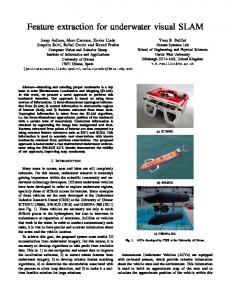
IV. F EATURE E XTRACTION Fig. 1. The sensor package: a conventional pinhole camera aligned with the SwissRanger SR-3000 ranger
poses are kept, since there are uncertainties associated to the feature locations. Hence, including feature locations in the state vector is expected to aid the filter in adjusting both camera poses and feature locations to better fit the observation data. Moreover, adding features to the state vector also means that observation noise can also be dealt with directly in the filter. If only the camera poses are included in the state vector, the raw observations need to be converted back into the relative camera pose transformations and the uncertainty of the transformation needs to be computed. Usually, some approximation is needed to compute the covariance of the transformation. For example, [3] assumed that range noise for each point has the same Gaussian distribution, whereas [12] derived the covariance matrix by sampling the error surface around the converged minima and then fitting a Gaussian to that local surface. For 3D laser scans, it is probably acceptable to assume that the range noise is the same for each point. But in the case of the SwissRanger, range noise associated with different pixels is quite different. The rest of this paper is structured as follows: Section III describes the visual sensor package. The 3D feature extraction and registration process is explained in Section IV. Section V covers the mathematical formulation of the EIF SLAM algorithm and the proposed information-efficient strategy. Section VI presents both simulation and experimental results. Discussion and concluding remarks are drawn in Sections VII and VIII where improvements and future work directions are also proposed. III. T HE V ISUAL 3D S ENSOR PACKAGE In this work, we have employed an improved version of the sensor package used in [6] which consists of a time-offlight range camera (SwissRanger SR-3000, low resolution, 176 × 144 pixels) and a higher resolution conventional camera (Point Grey Dragonfly2, 1024 × 768 pixels). The two cameras are fixed relative to each other as illustrated in Fig. II. The SwissRanger works on the principle of emitting modulated infra-red light on the scene with a 20 MHz frequency and
AND
F RAME R EGISTRATION
With no prior knowledge of the robot motion nor the scene, an efficient mechanism to estimate the relative pose between two images is required as an input to the filter. A popular choice drawn from computer vision as a fundamental component of many image registration and object recognition algorithms is the Scale Invariant Feature Transformation (SIFT) [9]. The main strength of SIFT is to produce a feature descriptor that allows quick comparisons with other features, and is rich enough to allow these comparisons to be highly discriminatory. Robust data association between SIFT features is particularly effective as the descriptor representation is designed to avoid problems due to boundary effects, i.e., smooth changes in location, orientation and scale do not cause radical changes in the feature vector. Furthermore, the representation is surprisingly resilient to deformations such as those caused by perspective effects [5]. The process for the frame registrations is as follows: firstly the two cameras are stereo calibrated (the MATLAB camera calibration toolbox at www.vision.caltech.edu/bouguetj/calib_doc was used for that purpose). SIFT features are then detected in the 2D camera image and matched across those in the previous images. Due to the offset between the two cameras, there is not a one-to-one corresponding pixel which can be obtained directly from the SwissRanger’s intensity image. However, given the calibration information, we can compute the 3D position at the point where the feature visual cue (bearing) should intersect the 3D point cloud. If a point can indeed be located around the intersection point and its distance is within the known SwissRanger’s measurement precision at that depth, we register this 3D point as a potential feature. This process is illustrated in Fig. 2 for a single SIFT point. Applying a least square 3D point set registration algorithm [8] and an outlier removal [13], we obtain a subset of features which can then be used for estimating the initial value of the new camera pose, with the previous camera pose as prior. All features are introduced as individual observations. Whilst under normal illumination condition hundreds of SIFT features can be extracted from each image, the number of features used at the actual filtering stage is significantly reduced by the above pairwise matching and registration with depth information.
IEEE TRANSACTION ON ROBOTICS AND AUTOMATION, VOL. X, NO. X, OCTOBER 2008
(a)
(b)
4
(c)
Fig. 2. Example of feature 2D to 3D registration. 2a 2D SIFT feature is first extracted from the traditional camera image before their 3D location is registered. 2b Bearing to feature intersecting with point cloud. Darker points indicate area of search in the point cloud around the bearing line depending on effective ranger resolution around that range. 2c Potential 3D feature projected back onto intensity image. Feature location is the closest match within given measurement uncertainty boundaries, yet it does not match exactly that of the pin-hole camera due to resolution differences and calibration accuracies.
V. E FFICIENT E XTENDED I NFORMATION F ILTER SLAM A. Information Efficient Filtering Strategy As described in the introduction section, in search and rescue scenario the desire is for a system which can deliver not only maximal information but also a human comprehensible presentation of the environment in minimal time. To do so, a “look-ahead and search backwards” algorithm is proposed. The idea is maximising data collection by buffering up all the information available but only choosing the most crucial data to be processed for mapping and localisation. Pseudocode for the proposed algorithm is described in Algorithm 1. Assuming the robot begins at the origin [0, 0, 0] of the global coordinate frame at time t = 0, the feature global poses can be established and be used as the first ’base’ frame, Fbase . For the following individual frames Fi , matching features are found between Fbase and each Fi , unless the number of common features reaches a predefined minimum or the number of frames being examined exceeds the look-ahead buffer size, The minimal number of common features is restricted by the 3D registration algorithm [8] while buffer size is an empirical number determined by the traveling speed of the device in order to guarantee a set of images with sufficient overlapping across the sequence, as well as the desired coarseness of the map. 3D registration is performed on each frame with respect to their matching Fbase (all global coordinates). Given new observations made at each new robot pose, information gain can be obtained without recovering the state vector which is the major computational expense in EIF SLAM. Since each new frame introduces a different number of new features, the information matrix is expanded with the minimal number of new features found across all frames in the buffer. This procedure is to guarantee that the expanded information matrixes contain the same number of elements so that their determinants can be compared. The camera pose at which the observations provide maximal information gain is added to the filter, and the corresponding frame is included as a new entry in the Fbase database. Frames in the look-ahead buffer previous to the new Fbase are dropped, and a new buffer is started from the consecutive frame after the last entry in Fbase .
The same procedure is repeated until the end of the trajectory. For the occasional circumstance when there are no matches between frames in the look-ahead buffer and frames in the Fbase database, matching is attempted with the previously dropped frames. If one of those frames provides sufficient matching features, it will be treated as a new frame and both will be updated in the filter. This mechanism ensures crucial information can be added back to the filter at any time to mitigate such undesirable situation in search and rescue as when rescuers become rescuees themselves. Although the robot is not processing every frame it acquired during the traversed course, its comprehensive collection of information about the environment becomes handy when the “kidnap” situation manifests itself. The robot’s knowledge is not limited to a set of known positions as it is also in possession of additional non-filtered information from the scenes in between base positions which it can retrieve to potentially recover to a known position. While the sudden risk of not knowing its whereabouts is certainly always looming in such risky and unpredictable environment, the proposed mechanism nevertheless increases the chances for a robot to regain its estimated location based on past knowledge in an efficient manner. B. EIF SLAM Computational advantages of using an Extended Information Filter rather than an Extended Kalman Filter are now well known, particularly in situations where excessive information is to be processed. This work employs an EIF that maintains all the features as well as the entire sequence of camera poses in the state vector. New camera poses are initialized with respect to the best matching frame at a known pose and measurement updates are additive in the information form. The sensor package is assumed to operate in full 6 DoF without a process model, therefore the formulation of the filter becomes simpler and results in a naturally sparse information matrix: there is no motion prediction step to correlate the current state with previous states. For full 6 DoF SLAM, the state vector X contains a set of 3D features and a set of camera poses. The camera poses are represented as (xC , yC , zC , αC , βC , γC )
(1)
IEEE TRANSACTION ON ROBOTICS AND AUTOMATION, VOL. X, NO. X, OCTOBER 2008
Algorithm 1 EIF Look-Ahead and Backward Search while end of the image sequence not reached do if processing first frame, F0 then Initialise iMatrix and iVector Fbase = {F0 } else while i < end of look ahead buffer do Get next frame Fi Do data association between Fi and Fbase if More than 6 common features are matched then Get 3D registration of Fi if 3D registration successful then Init. new features (min. across the buffer), augment iMatrix and iVector Temporarily update filter wrt Fbase and save determinant of new iMatrix end if end if i=i+1 end while if At least one frame in look-ahead buffer then Find frame which updates iMatrix to have maximum determinant, Fj Update filter permanently with Fj Fbase = {Fbase , Fj } else Find match between frames in look-ahead buffer and last 5 frames not included in Fbase if Match found then Update filter with two new frames else Kidnap recovery mode end if end if end if end while
in which αC , βC and γC represents the ZYX Euler angle rotation and the corresponding rotation matrix is referred to as RP Y (αC , βC , γC ). A 3D point feature in the state vector is represented by (xF , yF , zF ) (2) expressed in the global coordinate frame. Let i represent the information vector and I be the associated information matrix. ˆ , the The relationship between the estimated state vector X corresponding covariance matrix P , the information vector i, and the information matrix I is ˆ = I −1 i, P = I −1 X
(3)
The first camera pose is chosen as the origin of the global coordinate system. At time t = 0, the state vector X contains only the initial camera pose [0, 0, 0, 0, 0, 0]T , and the corresponding 6×6 diagonal information Matrix I is filled with large diagonal values representing the camera starting at a known position. A 3D feature is detected by the sensor package as a pixel location u, v and a depth d. These observed parameters can
5
be written as a function of the local coordinates (xL , yL , zL ) of the 3D feature with respect to the current camera pose − fzxLL u fy v = (4) , p − zLL 2 + z2 d x2L + yL L where f is the focal length. For convenience this relationship is referred to as u xL v = H1 yL . (5) d zL The relation between the feature local coordinates and the state vector X, represented in global coordinates, is xL xF xC yL = RP Y (αC , βC , γC )T yF − yC (6) zL zF zC referred to as
xL yL = H2 (X). zL
Thus the observation model becomes u v = H(X) = H1 (H2 (X)) + w d
(7)
(8)
where w is the observation noise. It is assumed that w is (approximately) a zero mean Gaussian noise (3D vector). In the update step, the information vector and information matrix update can be described by T I(k + 1) = I(k) + ∇Hk+1 Q−1 k+1 ∇Hk+1 T i(k + 1) = i(k) + ∇Hk+1 Q−1 k+1 [z(k + 1)− ˆ ˆ −Hk+1 (X(k)) + ∇Hk+1 X(k)]
(9)
where Qk+1 is the covariance matrix of the observation noise wk+1 and z(k+1) is the observation vector. The corresponding ˆ + 1) can be computed by solving state vector estimation X(k a linear equation ˆ + 1) = i(k + 1) I(k + 1)X(k
(10)
Detailed derivation of the Jacobian can be found in [6]. In error covariance form, the determinant of the N × N covariance matrix indicates the volume of the N-dimensional uncertainty polyhedron of the filter. The smaller the volume, the more confident the filter is about its estimation. As the information matrix has an inverse relationship with the covariance matrix, as described by (3), the maximally informative frame must update the information matrix to have the largest determinant. We use the natural logarithm of the information matrix determinant, denoted as log(det(I(k + 1))), as the measurable quantity of this information update. As described in section V-A, in a sequence of overlapped images containing common features, each image is evaluated with respect to the base frame database, Fbase . Thus, in order to proceed with the actual update of the filter, the pose corresponding to the frame such that log(det(I(k + 1))) is maximized becomes the one added to the filter. An empirical threshold to gauge the update
IEEE TRANSACTION ON ROBOTICS AND AUTOMATION, VOL. X, NO. X, OCTOBER 2008
TABLE I P ERFORMANCE C OMPARISON
Measurement time(sec) No frames No features Max Matrix Size
Consecutive 968.17 300 530 3390
Buffer size 3 499.47 194 520 2724
6
VI. R ESULTS Buffer size 5 461.46 156 535 2541
The algorithm was first validated with computer simulated data to demonstrate its capabilities to produce a consistent SLAM output with known true robot and feature locations. Real data was then collected by the proposed sensor package while operating at a realistic sampling rate. The outcome of a reconstructed 3D dense map that closely resembles the environment being explored alongside pictures from the scene are presented to show the qualities of the strategy. A. Simulation Results
Fig. 3. Estimated covariance and estimation error in xC , yC , zC coordinates, using all 300 frames in piecewise polygonal trajectory
The simulation environment was generated in MATLAB. The camera traveled along a piecewise polygonal trajectory in 3D while continually rotating in 6D for 2 loops, and took observations at 300 equally distributed poses. 2000 features were randomly populated in the 20 × 6 × 20 meters environment. Table I summarizes the key performance improvements between traditional EIF and the proposed technique for two measures of map smoothness. It can be seen how, for instance, with a buffer size of 3 frames (the next consecutive frame plus 2 look-ahead frames) computational time is reduced to almost 1/2 of the consecutive case, as the dimensionality of the information matrix is reduced by nearly 1/3 against the full size experiment. The estimated error in the robot pose when compared against the ground truth are pictured in Fig. 3 and 4 for the 95% uncertainty bounds test, which show the consistency of the estimation over the robot pose for the two buffer size cases depicted. Three dimensional views of the camera poses and map can be seen in Fig. 5a and 5b. A detail for the case of a sharp rectangular turn is also depicted in Fig. 5c to gain a better understanding of the evolution of the pose distributions. B. Experimental Results
Fig. 4. Estimated covariance and estimation error in xC , yC , zC coordinates, using 163 out of 300 frames in piecewise polygonal trajectory
quality is also defined based on the desired coarseness of the map. When the maximum determinant is smaller than this threshold, meaning there is little information gain in updating the filter with the current sequence in the look-ahead buffer, all the frames in the sequence are updated to maximize the information gain.
For experimental evaluation, scans were collected from a mock-up search and rescue arena. The sensor package was hand-held and operated at a combined sampling rate of approximately 5Hz in a modern laptop, partly due to the extra time consumed by saving data to the hard drive for later batch-processing. The sensor package is manoeuvred in relatively slow motion and it is therefore assumed to produce synchronized data from both cameras at this frequency. 366 scans were collected in about 1 minute and 13 seconds. A sequence of 4 frames from the data set is shown in Fig. 6. By applying the proposed approach, 118 out of the 366 scans were automatically selected to be added to the filtering process based on the estimator’s uncertainty belief. The final distribution of the selected frames over the entire data sequence is depicted in Fig. 7. The state vector ended up containing a total of 2550 elements (118 camera poses (6D) and 614 features (3D)). The final information matrix is illustrated in Fig. 8. The entire processing time was 1530 seconds which could be further reduced by exploiting the sparseness of the information matrix. The final dense 3D map constructed by superimposing the local point clouds to the filtered camera trajectory is shown in Fig. 9a, where texture
IEEE TRANSACTION ON ROBOTICS AND AUTOMATION, VOL. X, NO. X, OCTOBER 2008
(a)
(b)
7
(c)
Fig. 5. Example trajectories depicting a polygon shaped 3D motion. 5a 3D view of the full trajectory (2 loops). 5b Zoomed-in detail. Dark (blue) ellipsoids show 95% uncertainty boundaries of the robot’s estimated trajectories. Light (aqua)lines indicate robot’s current heading. Stars (red) illustrate feature locations. 5c Zoomed-in section of a simulation with simple rectangle trajectory. It can be seen in the zoomed-in view how more estimations were needed after the sharp turn indicating a decrease in the confidence levels. Once that was regained estimations became once again more sparse along the trajectory. It also demonstrated how feature distribution influenced the frame selection.
(a) Base frame 1
(b) frame 2
Fig. 8. Sparse information matrix,where dark (blue) blocks show the correlations.
(c) frame 3
(d) Chosen frame
Fig. 6. Sample sequence of 4 images, where (d) is the one finally chosen to be incorporated into the filter.
set. The 3D maps constructed by these methods are presented in Fig. 9b and 9c respectively, and further discussed in the following Section. VII. D ISCUSSION
Fig. 7.
Distribution of selected frames over the entire data sequence.
has been projected back into the cloud points visible in the 2D camera images (field of view of the SwissRanger is very close to but slightly larger than the field of view of the traditional camera). A more detailed reconstruction of a small corner section and some of its constituent frames is displayed in Fig. 10. Results were also collected for comparison by implementing a standard EIF SLAM and the direct registration of 3D features between consecutive frames over the full data
Unlike most conventional fixed time step or fixed displacement approaches, our proposed technique exhibits the ability to fuse the minimal information required based on the robot uncertainty belief, which is in turn dynamically influenced by the complexity of the robot trajectory, the observation quality and the estimation of the last known robot position. Results depicted in zoomed-in Fig. 5b and 5c are particularly relevant, as they clearly show how at areas with a reduced number of features and sharper motions, such as corners in the depicted trajectory, information losses due to sudden changes in the scenes are compensated for by the nature of the proposed filtering mechanism. As robot pose uncertainty increases and information gets scarcer, a larger number of pose estimations are necessary to compensate for the reduced quality of the observations within the robot’s field of view. Thus the consistency of the filter is maintained despite this information loss, as shown earlier in Fig. 4 during simulation.
IEEE TRANSACTION ON ROBOTICS AND AUTOMATION, VOL. X, NO. X, OCTOBER 2008
(a)
8
(b)
(c)
(d)
Fig. 9. 3D map obtained from filtering of 118 (out of 366) frames of the 6 × 3 meters search and rescue arena. 9a Resulting 3D point cloud map of the entire area superimposed on the selected estimated camera poses, as viewed from one of the corners. 9b EIF SLAM result obtained by incorporating all frames. 9c Final 3D point cloud reconstructed by direct 3D registration between consecutive frames. Overall view of the search and rescue arena is shown in 9d.
(a)
(b)
(c)
(d)
Fig. 10. Partial 3D map reconstructed for the corner area covered by frames 94 to 140 (46 frames). Only 14 frames were actually processed in the filter which was sufficient to produce the highly detailed map seen in 10a (We choose to present this corner with advertising tool for easy scene recognition for the readers). 10b Frame 94. 10c Frame 118. 10d Frame 140.
Although the concept of information gain is very abstract, it becomes more intuitive when the filter’s decision is compared with visual information side by side as shown in Fig. 6. Frame 6a is taken at the last known robot position. Frame 6b, 6c and 6d are the following frames in the sequence. By visual examination, it is apparent to a human observer that frame 6d has better clarity and covers more unexplored territory compared to the other two preceding images, which in the filter’s ‘comprehension’ means better quality of matching features and greater number of more accurately initialized new features. To justify the quality of our proposed algorithm, a traditional EIF SLAM and direct 3D registration has also been implemented using the same data set. Results are illustrated in Fig. 9b and 9c respectively. Despite the long computational time required to perform EIF SLAM over the entire frame sequence (4 hours and 20 minutes in a fast parallel cluster machine, with a final matrix of 7275 × 7275 elements), a reasonable result is obtained with full SLAM, while a large accumulated error of more than 2 meters in the X direction was the result of direct 3D registration. From these figures one may observe that the 3D map obtained by using the proposed
IEEE TRANSACTION ON ROBOTICS AND AUTOMATION, VOL. X, NO. X, OCTOBER 2008
Fig. 11. xC covariance evolution of frame 89 in simulation experiment. Red dashed line indicates covariances when all frames were processed while blue line shows the covariances when only using selected frames.
efficient methodology is even slightly better than the one using all the frames, and point clouds alignments are visually neater upon loop closure. This may appear somewhat surprising at first, as it can be reasonably expected that more observations should theoretically lead towards better filter estimations. In fact, further analysis of the simulation presented in Section VI-A demonstrated that using all the frames produced a superior pose and map estimation as expected. Pose covariance xC of one of the furthest away (in more error) poses in the simulated robot trajectory for the full and reduced number of frames are presented in Fig. 11. Covariances of other state variables also followed the same tendency. However, in the real world, observation model uncertainties and round-off errors introduced by the correspondences between 3D point clouds and 2D features have practically meant that incorporating all the information not only did indeed prolong the computing process as expected, but also introduced more observation errors in the system that for longer runs, ultimately resulted in marginally poorer results. Due to the nature of the hand-held experiment in 6D, it is unrealistic to compare the estimation with ground truth, so results with real data can only be provided at a qualitative level. Camera covariances xC , yC and zC are nevertheless illustrated in Fig. 12 to show to some extent the bounded nature of the errors and the filter corrections. From all the experiments presented, we can conclude that the proposed algorithm is most valid for handling real data sets and constitutes a significant step in visually improving the map quality of 3D unstructured environments in an efficient manner. VIII. C ONCLUSION
AND
F UTURE W ORK
We have presented an approach for producing 3D dense map with a combination of vision and range sensors. The proposed algorithm not only produces consistent SLAM outputs but also dynamically incorporates observations into the estimation process for robust 3D navigation in unstructured terrain. Results have shown that by gauging the information gain in each frame, we can automatically incorporate the most apt observations for the purpose of SLAM and extract comprehensive findings about the collective environment we intend to explore.
9
Fig. 12. xC (red circle), yC (blue cross), zC (green square) covariance of camera poses. Markers indicate the frames that are incorporated in the filter.
Although the current results appear promising, there are still some limitations to the proposed algorithm due to various factors: •
•
•
SIFT is of limited assistance when dealing with more dramatic changes in view angles, especially with narrower field of view cameras. More challenging egomotions are expected when the sensor package is mounted on a continuously moving USAR platform, instead of handheld as shown here. The SwissRanger tends to return noisy measurements when it encounters glass surfaces. It also returns ambiguous measurements when measuring beyond its range, hence limiting its use to constrained environments. Exploration of larger areas. Integration with another method such as sub-mapping is a rational approach to address the scalability issue.
The proposed knowledge-driven algorithm can be regarded as trade off between computational efficiency and information loss. We believe it is critical for intelligent systems in the field to be able to attribute a measure of relevance to the information attained given the objective at hand. It is not hard to imagine how when exploring inside a collapsed building, it seems of higher priority to place exits, stairways, large cavities etc. with relative accuracy, rather than yielding undue emphasis on generating perfectly straight walls. Active trajectory planning and exploration seem like natural companions to our proposed strategy in order to best comprehend the environment surrounding the robot, in minimum time and within bounded estimation errors. This is decidedly the case in the domain of autonomous robotics for search and rescue contemplated under the umbrella of this research work.
ACKNOWLEDGMENT This work is supported by the Australian Research Council (ARC) through its Centre of Excellence programme, and by the New South Wales State Government. The ARC Centre of Excellence for Autonomous Systems (CAS) is a partnership between the University of Technology Sydney, the University of Sydney and the University of New South Wales.
IEEE TRANSACTION ON ROBOTICS AND AUTOMATION, VOL. X, NO. X, OCTOBER 2008
R EFERENCES [1] G. Dissanayake, P. Newman, S. Clark, H. Durrant-Whyte, M. Csorba. “A solution to the Simultaneous Localization and Map Building (SLAM) Problem”, IEEE Trans. on Robotics and Automation, vol. 17, pp. 229– 241, 2001 [2] K. Ohno, S. Tadokoro, “Dense 3D Map Building Based on LRF Data and Color Image Fusion”, in Proceedings of the IEEE Int. Conf. on Intelligent Robot and Systems, pp. 1774–1779, 2005. [3] F. Lu, E. Milios, “Globally Consistent Range Scan Alignment for Environment Mapping”, in Autonomous Robots, vol. 4(4), pp. 333–349, 1997. [4] T. Oggier, M. Lehmann, R. Kaufmann, M. Schweizer, M. Richter, P. Metzler, G. Lang, F. Lustenberger, N. Blanc, “ An All-Solid-State Optical Range Camera for 3D Real-Time Imaging with Sub-Centimeter Depth Resolution (SwissRanger)”, in Proceedings of the SPIE, vol. 5249, pp. 534–545, 2004. [5] K. Mikolajczyk, C. Schmid, “A Performance Evaluation of Local Descriptors”, in Proceedings of the IEEE Comp. Soc. Conf. on Computer Vision and Pattern Recognition, pp. 257–263, 2003. [6] L. P. Ellekilde, S. Huang, J. Valls Mir´o, G. Dissanayake, “Dense 3D Map Construction for Indoor Search and Rescue”, Journal of Field Robotics, vol. 24(1/2), pp. 71–89, 2007. [7] W. Zhou, J. Valls Mir´o, G. Dissanayake, “Information Efficient 3D Visual SLAM in Unstructured Domains”, in Proceedings of the IEEE Int. Conf. on Intel. Sensors, Sensor Networks and Information Processing, pp. 323–328, 2007. [8] K. S. Arun, T. S. Huang, S. D. Blostein, “Least Square Fitting of Two 3-D Point Sets”, IEEE Pattern Analysis and Machine Intelligence, vol. 9(5), pp. 698–700, 1987. [9] D. G. Lowe, ”Distinctive Image features from Scale-Invariant Keypoints” Int. Journal of Computer Vision, vol. 60(2), pp. 91–110, 2004. [10] R. M. Eustice, O. Pizarro, H. Singh, ”Visually Augmented Navigation in an Unstructured Environment Using a Delayed State History”, in Proceedings of the IEEE International Conference on Robotics and Automation, pp. 25–32, 2004. [11] R. M. Eustice, H. Singh, J. J. Leonard, “Exactly Sparse Delayed-Sate Filters”, in Proceedings of the IEEE Int. Conference on Robotics and Automation, pp. 2417–2424, 2005. [12] D. M. Cole, P. M. Newman, “Using Laser Range Data for 3D SLAM in Outdoor Environments”, in Proceedings of the IEEE Int. Conference on Robotics and Automation, pp. 1556–1563, 2006. [13] M. Fischler, R. Bolles, “RANdom SAmpling Consensus: A Paradigm for Model Fitting with Application to Image Analysis and Automated Cartography”, Communications of the Association for Computing Machinery, vol. 24, pp. 381–395, 1981. [14] F. Dellaert, “Square Root SAM”, in Proceedings of Robotics: Science and Systems, 2005. [15] A. J. Castellanos, J. M. M. Montiel, J. Neira, & J. D. Tard´os, ”Sensor Influence in The Performance of Simultaneous Mobile Robot Localization and Map Building”, in 6th Int. Symp. on Experimental Robotics, pp. 203–212, 1999. [16] S. Se, D. G. Lowe, & J. Little, ”Mobile Robot Localization and Mapping with Uncertainty Using Scale-Invariant Visual Landmarks”, Int. Journal of Robotics Research, vol. 21(8), pp. 735–758, 2002. [17] J. W. Weingarten, G. Gruener, & R. Siegwart, ”A State-of-Art 3D Sensor for Robot Navigation”, in Proceedings of the IEEE Int. Conf. on Intelligent Robot and Systems, Sendai, Japan, pp. 2155–2160, 2004. [18] J. M. Saez, & F. Escolano, ”Entropy Minimization SLAM using Stereo Vision”, in Proceedings of the IEEE Int. Conf. on Robotics and Automation, Barcelona, Spain. pp. 36–43, 2005. [19] J. M. Saez, & F. Escolano, ”6DOF Entropy Minimization SLAM”, in Proceedings of the IEEE Int. Conf. on Robotics and Automation, pp. 1548–1555, 2006. [20] R. Sim, P. Elinas, M. Griffin, & J. J. Little, ”Vision-Based SLAM using Rao-Blackwellised Particle Filter”, Intl. Joint Conf. on Artificial Intelligence workshop on Reasoning with Uncertainty in Robotics, Edinburgh, Scotland, 2005. [21] M. N. Dailey, & M. Parnichkun, ”Landmark-Based Simultaneous Localization and Mapping with Stereo Vision”, in Proceeding of the IEEE Asian Conf. on Industrial Automation and Robotics, Bangkok, Thailand. pp. 108–113, 2005. [22] S. Se, D. G. Lowe, & J. J. Little, ”Vision-Based Global Localization and Mapping for Mobile Robots”, IEEE Trans. on Robotics, vol.21(3), pp. 364–375, 2005.
10
[23] S. Huang, Z. Wang, & G. Dissanayake, ”Mapping Large Scale Environments Using Relative Position Information Among Landmarks”, in Proceedings of the IEEE Int. Conf. on Robotics and Automation, pp. 2297–2302, 2006. [24] P. Newman, D. Cole, & K. Ho, ”Outdoor SLAM Using Visual Appearance and Laser Ranging”, in Proceedings of the IEEE Int. Conf. on Robotics and Automation, pp. 1180–1187, 2006. [25] D. M. Cole, & P. Newman, ”Using Laser Range Data for 3D SLAM in Outdoor Environments”, in Proceedings IEEE Int. Conf. on Robotics and Automation, pp. 1556–1563, 2006. [26] S. Se, & P. Jasiobedzki, ”Photo-Realistic 3D Model Reconstruction”, in Proceedings of the IEEE Int. Conf. on Robotics and Automation workshop on SLAM, pp. 3076–3082, 2006.
Weizhen Zhou received her B.Eng. degree in Computer System Engineering at the University of Technology, Sydney in 2004. She is currently working towards her Ph.D. at the UTS node of the Australian Research Council (ARC) Centre of Excellence for Autonomous Systems. Her research is focused on visual simultaneous localization and mapping, with particular interest in 3D environments.
Jaime Valls Mir´o received a B.Eng. and M.Eng. degrees in Computer Science Systems from the Valencia Polytechnic University, Spain, in 1990 and 1993 respectively. He received his Ph.D. in Robotics from Middlesex University, England, in 1998 and then worked for 5 years in the underwater robot industry. Currently, he is a Senior Research Fellow at the University of Technology, Sydney node of the ARC Centre of Excellence for Autonomous Systems. His research activities span autonomous navigation and mapping of unstructured scenarios urban search and rescue in particular, visual SLAM, underwater and health care robotics, kino-dynamic manipulator control and human-robot interaction.
Gamini Dissanayake is the James N. Kirby Professor of Mechanical and Mechatronic Engineering at University of Technology, Sydney. He has expertise in a broad range of topics in robotics including robot localisation, mapping and SLAM using sensors such as laser, radar, vision and inertial measurement units, terrain mapping, multi-robot coordination for SLAM, target tracking and probabilistic search, motion planning for single and multiple robot manipulators, legged robots and cranes, and application of robotic systems in urban search and rescue. He leads the UTS node of the ARC Centre of Excellence for Autonomous Systems. He graduated in Mechanical/Production Engineering from the University of Peradeniya, Sri Lanka in 1977. He received his M.Sc. in Machine Tool Technology and Ph.D. in Mechanical Engineering (Robotics) from the University of Birmingham, England in 1981 and 1985 respectively.