data from all the activated nodes; and (ii) comparable to another. IQ-aware routing protocol that uses an exhaustive brute-force search to approximate and prune ...
This full text paper was peer reviewed at the direction of IEEE Communications Society subject matter experts for publication in the IEEE INFOCOM 2010 proceedings This paper was presented as part of the main Technical Program at IEEE INFOCOM 2010.
Information Quality Aware Routing in Event-Driven Sensor Networks Hwee-Xian Tan∗ , Mun-Choon Chan∗ , Wendong Xiao† , Peng-Yong Kong† and Chen-Khong Tham† ∗ School
of Computing, National University of Singapore (NUS) for Infocomm Research (I2 R), Singapore {hweexian, chanmc}@comp.nus.edu.sg, {wxiao, kongpy, cktham}@i2r.a-star.edu.sg † Institute
Abstract—Upon the occurrence of a phenomenon of interest in a wireless sensor network, multiple sensors may be activated, leading to data implosion and redundancy. Data aggregation and/or fusion techniques exploit spatio-temporal correlation among sensory data to reduce traffic load and mitigate congestion. However, this is often at the expense of loss in Information Quality (IQ) of data that is collected at the fusion center. In this work, we address the problem of finding the leastcost routing tree that satisfies a given IQ constraint. We note that the optimal least-cost routing solution is a variation of the classical NP-hard Steiner tree problem in graphs, which incurs high overheads as it requires knowledge of the entire network topology and individual IQ contributions of each activated sensor node. We tackle these issues by proposing: (i) a topology-aware histogram-based aggregation structure that encapsulates the cost of including the IQ contribution of each activated node in a compact and efficient way; and (ii) a greedy heuristic to approximate and prune a least-cost aggregation routing path. We show that the performance of our IQ-aware routing protocol is: (i) bounded by a distance-based aggregation tree that collects data from all the activated nodes; and (ii) comparable to another IQ-aware routing protocol that uses an exhaustive brute-force search to approximate and prune the least-cost aggregation tree.
I. I NTRODUCTION Wireless Sensor Networks (WSNs) comprise of large numbers of sensor nodes that are deployed in the terrain to sense physical phenomena of interests (PoIs) [1] and transmit the sensed data to one or more centralized sinks for realtime processing and decision-making [2]. These networks can be used for a multitude of applications, such as healthcare monitoring and tactical surveillance. However, the successful deployment and maintenance of sensor networks is challenged by several factors, such as temporal link connectivity as well as limited bandwidth, energy and processing capabilities. We focus on a particular class of sensor networks that is deployed specifically for the detection of PoIs. Such networks have convergecast traffic characteristics [3] and are considered to be event-driven as sensory data is typically generated only when the PoI is detected. Upon the occurrence of a PoI (such as a fire hazard or an elderly person falling in a monitored home environment), multiple sensors may be activated concurrently. This may lead to severe data implosion and redundancy [4], especially in extremely dense networks. To mitigate the effects of congestion and reduce medium access contention, data aggregation and/or fusion techniques are often used to suppress data from multiple sensor sources.
These schemes exploit spatio-temporal correlation among sensory data to reduce traffic load and energy consumption. However, this often comes at the expense of loss in information quality (IQ) of data that is collected at the fusion center. In event-driven sensor networks, this is equivalent to a loss in (event) detection accuracy, which results in overall lower system and network reliability. As such, there exists an obvious trade-off between information quality and energy efficiency in data aggregation and/or fusion schemes [5]. We address the problem of finding a least-cost routing tree that satisfies a given IQ constraint, noting that the optimal least-cost routing solution is a variation of the classical NPhard Steiner tree problem in graphs [6]. In the context of eventdriven sensor networks, the original Steiner tree problem is to find a Steiner Minimum Tree that spans the fusion center and entire set of activated sensor nodes (denoted as Va ) that detect the PoI. However, it is unnecessary and expensive for all the sensors in Va to transmit their data to the fusion center. Ideally, an IQ-aware event-driven routing scheme only needs to aggregate sufficient sensory data from a subset of activated nodes Vτ ⊆ Va to meet the IQ constraint. We refer to this as a subset-τ Steiner Tree (SST) problem. Clearly, the latter is a harder problem than the Steiner tree, as the: (i) set of activated nodes Va and IQ contribution of each activated node are not known a priori until the PoI occurs; and (ii) subset of activated nodes Vτ whose aggregated IQ meets the given constraint is not unique. Knowledge of the entire network topology and individual IQ contributions of each activated sensor node are quintessential to find the least-cost SST that satisfies the required IQ. Unfortunately, this incurs extensive computational, storage as well as communication overheads, and is not a feasible approach in resource-constrained WSNs. We tackle the fundamental issues in constructing an optimal least-cost SST in an IQ-aware event-driven sensor network by proposing: (i) a topology-aware histogram-based aggregation structure that encapsulates the cost of including the IQ contribution of each activated node, in a compact and efficient way; and (ii) a greedy heuristic to approximate and prune a least-cost aggregation routing path. The proposed IQAware Routing (IQAR) protocol constructs an initial distancebased aggregation tree that spans all the sensors in the WSN. When a PoI occurs, activated sensors forward their data to the fusion center using the underlying pre-built distance-based aggregation tree. At each hop along the routing path, the IQ
978-1-4244-5837-0/10/$26.00 ©2010 IEEE
This full text paper was peer reviewed at the direction of IEEE Communications Society subject matter experts for publication in the IEEE INFOCOM 2010 proceedings This paper was presented as part of the main Technical Program at IEEE INFOCOM 2010.
contributions of each activated sensor and its downstream (forwarding) nodes are discretized and incorporated together, to form a topology-aware histogram-based aggregation structure. When data packets (with incorporated histograms) reach the fusion center, it utilizes a greedy heuristic to prune the original aggregation tree such that: (i) aggregated IQ of the resulting pruned tree satisfies a given IQ constraint; and (ii) total cost of collecting data from activated nodes in the pruned tree is minimized. The pruning process is recursively executed at each forwarding node along the initial aggregation tree. Activated sensor nodes that are not part of the pruned routing tree suppress their data for a time epoch. When the time epoch expires, activated nodes whose data have been suppressed resume the forwarding of their data to the fusion center. This allows the routing protocol to be adaptive towards dynamic changes in the network and phenomena of interest. We show that the performance of IQAR is upper bounded by a distance-based aggregation tree that collects data from all the activated nodes, and comparable to another IQ-aware routing protocol that uses an exhaustive brute-force search to approximate and prune the least-cost aggregation tree. The rest of this paper is organized as follows: Section II discusses background and related work. The system model is described in Section III. Details of the topology-aware histogram-based aggregation structure and IQAR are presented in Sections IV and V respectively. We evaluate the performance of IQAR in Section VI and conclude in Section VII. II. BACKGROUND AND R ELATED W ORK A. Aggregation and/or Fusion based Routing Data aggregation and/or fusion based-routing has gained significant popularity in WSNs due to the obvious benefits brought about by in-network processing [4] [7]. These schemes exploit presence of spatio-temporal correlation [8] among sensory data to reduce traffic load, which subsequently alleviates medium contention as well as reduces transmission costs and end-to-end delays. Generally, such techniques can be classified into two main categories, viz. structure-less and structured. In structure-less techniques [9] [10], data aggregation occurs opportunistically only when data flows happen to meet at the same time at the same intermediate forwarding node. There is no deliberate attempt to delay any transmission or re-route packets such that these encounters take place. Consequently, structure-less approaches incur shorter delays when the network is lightly loaded, as data is forwarded towards the fusion center using an underlying shortest-path or least-cost routing algorithm. However, such approaches do not scale well with large networks or high traffic volumes as aggregation opportunities are not maximized. In structured techniques [11] [12] [13] [14], routing paths are computed and maintained to allow efficient data aggregation. The routing path is influenced primarily by the amount of data reduction that can be achieved by data compression before it is forwarded to the fusion center. Such techniques incur relatively higher overheads to maintain the network structure, and are associated with a delay factor, as intermediate
forwarding nodes have to wait for their upstream nodes to send data to them, before aggregating these data packets and forwarding them to the fusion center. Nevertheless, structured techniques can achieve significant energy savings, as data is maximally aggregated along the forwarding paths. They are well-suited for WSNs with slow-varying traffic characteristics, such as periodic monitoring. Many structured schemes adopt a clustering approach [15] [16] [17], whereby sensory data is first transmitted to a cluster head for aggregation before being forwarded to the fusion center. These existing aggregation-based approaches require all sensory data to be collected at the fusion center, which results in high data redundancy and energy costs. As not all the data has to be transmitted to the fusion center for reliable PoI detection in IQAR, it can achieve significant energy savings over generic aggregation-based routing schemes. B. Information-Quality (IQ) Aware Routing Unlike aggregation-based routing schemes, IQ-aware routing schemes consider the information content of data during data aggregation and forwarding. Information-directed approaches such as IDSQ and CADR [18] [19] [20] handle data querying and routing using energy-efficient techniques, while minimizing delay and bandwidth consumption. At each step along the routing path, the neighboring node with the highest predicted information gain is selected to be the next-hop, and the fused data is transmitted to the fusion center as soon as it satisfies a given IQ threshold. These existing schemes differ from IQAR in that they are query-based, targeted at tracking applications, and data flows along a single path which is initiated from the fusion center. However, IQAR adopts a treebased approach and is targeted at event detection in WSNs. The emphasis of existing literature on event-detection in sensor networks [1] [21] [22] [23] is on designing energyefficient hypothesis testing models to detect the presence of the PoI. Most of these schemes do not consider routing, and are based on a centralized one-hop sensor network topology. In contrast, IQAR addresses both event detection and multi-hop routing simultaneously. III. S YSTEM M ODEL In an event-detection WSN, the information quality of concern is related to the detection accuracy of the system. In this section, we detail how IQ is mapped onto the targeted detection and false alarm probabilities Pd and Pf using sequential detection [24] [25]. We also describe the Likelihood Ratio Test (LRT) [26], which has been shown to be the optimal detection scheme that maximizes detection probability. The network is modeled as a graph G = {V, E}, where V = {v0 , v1 , v2 , ..., vn } denotes the set of n sensor nodes and fusion center v0 , and E denotes the set of edges (or links) between any two nodes. An edge eij ∈ E represents the existence of a communication link between two arbitrary sensors vi and vj . We let hypothesis H1 denote the presence of a PoI in the sensor network; H0 denotes the corresponding absence of the PoI. The probabilities P (H1 ) = p and P (H0 ) = 1 − p, where
This full text paper was peer reviewed at the direction of IEEE Communications Society subject matter experts for publication in the IEEE INFOCOM 2010 proceedings This paper was presented as part of the main Technical Program at IEEE INFOCOM 2010.
0 < p < 1, are known a priori. Each node independently senses and collects data about the environment periodically. When conditioned upon the hypothesis Hi , i ∈ {0, 1}, sensor observations are assumed to be independently and identically distributed (i.i.d.) at each sensor as well as across sensors [25]. A. Event Detection at Sensor The independent signal yi observed by a node vi is: � wi if H0 (PoI is absent); yi = f (ri ) + wi if H1 (PoI is present),
(1)
2 where wi ∼ N (0, σw ) is the noise seen by vi that follows a normal distribution with mean 0 and standard deviation σw ; ri is the the distance between vi and the PoI; and f is a function that monotonically decreases with increasing ri . For each sampled signal yi , vi makes a per-sample binary decision bi ∈ {0, 1} such that: � 0 if yi < Ti ; (2) bi = 1 otherwise,
where Ti is the per-sample threshold of vi . The per-sample probability of false alarm pi0 by vi is independent of its location, and given by [1]: Ti (3) pi0 = P (bi = 1|H0 ) = Q( ), σw where Q(x) is the Gaussian Q-function of a standard normal distribution. The corresponding per-sample probability of detection pi1 (where pi1 > pi0 ) at vi is dependent on the distance ri between vi and the PoI, and given by: Ti − f (ri ) pi1 = P (bi = 1|H1 ) = Q( ). (4) σw Although each node senses the environment at periodic intervals, it is infeasible for each sample to be transmitted to the fusion center v0 , due to limited network bandwidth and energy constraints of the sensors. Consequently, a data packet is generated by vi to be transmitted to v0 only if vi detects the presence of a PoI and becomes activated (when bi = 1). B. Event Detection at Fusion Center The role of the fusion center v0 is to detect the presence of ˆ = {H0 , H1 }, the PoI by making a global binary decision H based on the data that it has received from the set of activated nodes Va . Let B = {b1 , b2 , ..., b|Va | } be the set of per-sample binary decisions that v0 receives from each va ∈ Va in a time epoch. The optimal fusion rule for v0 using data from all the activated nodes is the Likelihood Ratio Test (LRT) [25] [26]: P (b1 , b2 , ..., b|Va | |H1 ) H1 1 − p � Λ(B) = . (5) P (b1 , b2 , ..., b|Va | |H0 ) H0 p ˆ = Hence, v0 makes the decision that the PoI is present (H H1 ) if Λ(B) ≥ 1−p . Notice that for small values of the a p priori probability p, the likelihood ratio Λ(B) required for the PoI to be detected is much larger than for bigger values of p. As a numerical example, consider p = 0.01; then, the PoI can be detected only when Λ(B) ≥ 1−0.01 0.01 = 99. In contrast, if p = 0.1, the PoI can be detected when Λ(B) ≥ 1−0.1 0.1 = 9.
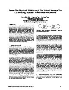
C. Sequential Detection To reduce the amount of data that is collected for v0 to make ˆ we adopt the sequential an accurate global binary decision H, detection model which is based on the Sequential Probability Ratio Test (SPRT) proposed by A. Wald [24]. In SPRT, the amount of data required is a random variable dependent on the prior data that has been obtained thus far. Let Xa = {x1 , x2 , ..., x|Va | } be the sequence whereby data is collected from each activated node va ∈ Va . Using sequential detection, data acquisition can terminate at the earliest subsequence of fused local data Xτ = {x1 , x2 , ..., xτ } ⊆ Xa ˆ = {H0 , H1 } can be made., thus when the decision H minimizing the cost of data acquisition and PoI detection. We consider an arbitrary node vi with hopcount h along the routing path. The neighboring node vj with hopcount h + 1 and which uses vi to forward packets to the fusion center is considered an upstream node of vi ; the set of upstream nodes of vi is denoted as Viu . In the same manner, vi is known as the downstream node of vj . In Figure 1, v1 , v2 and v3 are the upstream nodes of v0 such that V0u = {v1 , v2 , v3 }. Since observations across sensor nodes are i.i.d., the cumulative log-likelihood ratio S0 at the fusion center v0 is: |Va |
S0 = log Λ(B) = log
�
Λ(bi ).
(6)
i=1
The corresponding cumulative log-likelihood ratio Si at vi comprises of its log-likelihood ratio and the cumulative loglikelihood ratios of each upstream node vj ∈ Viu , such that: � Si = log Λ(bi ) + Sj . (7) vj ∈Viu
The stopping rule γi = {0, 1} is computed after each incorporated data from vi , and is dependent on the targeted detection and false alarm probabilities Pd and Pf . It determines if the current sequence of incorporated data along the ˆ to be made routing path is sufficient for the global decision H at v0 , and is given by Wald’s Equation [24]: � 0 if A < Si < B; (8) γi = 1 otherwise, 1−Pd where A = log( 1−P ); and B = log( PPfd ). This stopping rule is f considered to be optimal in sequential detection, as it results in the least possible amount of data required for decision making. If γi = 0, the current sequence of data collected is ˆ to be made and more insufficient for a global decision H data samples have to be acquired. However, when γi = 1, the ˆ can be made based on the current sequence of decision H incorporated data, according to: � H0 if Si ≤ A; ˆ (9) H= H1 otherwise (Si ≥ B).
Hence, additional data need not be collected from other sensor nodes and data acquisition can be terminated to minimize the overall cost while satisfying the Pd and Pf constraints.
This full text paper was peer reviewed at the direction of IEEE Communications Society subject matter experts for publication in the IEEE INFOCOM 2010 proceedings This paper was presented as part of the main Technical Program at IEEE INFOCOM 2010.
v1
Based on this sequential detection model, the minimum cumulative log-likelihood ratio required for v0 to detect the PoI with sufficient accuracy is S0 ≥ B. The IQ threshold IT can then be directly mapped to B such that IT = B. The corresponding IQ provided by each node vi is hence given by qi = log Λ(bi ). As an illustration, the IQ provided by v7 and v8 in Figure 1 are q7 = log Λ(b7 ) = 0.4 and q8 = log Λ(b8 ) = 0.6 respectively. The corresponding cumulative log-likelihood ratio at v3 is S3 = log Λ(b3 )+q7 +q8 = 1.2+0.4+0.6 = 2.2.
v0
Each link between a pair of nodes vi and vj is associated with some cost Cij . In the absence of power control, the perhop link cost Cij is independent of the distance between vi and vj , and can be computed as a function of: (i) processing energy required to process and perform data aggregation on a data packet; (ii) transmission energy expended by vi ; and (iii) reception energy expended by neighbors of the transmitting node vi upon reception of the packet in a wireless medium. One implicit assumption in our cost model is that each data packet is of the same size, regardless of the amount of data that has been fused together from different nodes. We explain our assumptions behind this model in Section IV.
v4 v5
v7 v3
0.1
1.0
1.7
v9
0.2
v 10
0.3
v 11
0.8
v 12
0.4
v6
0.5
0.4
1.2
v8
Fig. 1.
D. Cost Model
v2
0.3
0.6
Fusion center v0 with three upstream nodes v1 , v2 and v3 .
IV. T OPOLOGY-AWARE H ISTOGRAM -BASED AGGREGATION We first illustrate our approach using the network topology in Figure 1, where the fusion center v0 has three (direct) upstream nodes such that V0u = {v1 , v2 , v3 }. All the nodes are assumed to be activated; the number associated with each node vi represents its IQ contribution qi = log Λ(bi ). The cost of data transmission across each link is assumed to be of unit cost, i.e. Cij = 1 ∀eij ∈ E, as the packet size remains constant across each link in our IQ aggregation scheme.
E. Problem Formulation
A. Motivation
Given the network G = {V, E}, set of activated nodes Va , IQ contribution qa of each activated node va ∈ Va and IQ threshold IT , our objective is to design an IQ-aware routing protocol that detects the PoI with an IQ of at least IT using minimal cost. Formally, we want to find a subset-τ Steiner Tree, which is a Steiner Minimum Tree Gτ = {Vτ , Eτ } ⊆ G that spans the fusion center v0 and all nodes in Vτ ⊆ Va , such that: (i) aggregated IQ collected from Vτ exceeds IT ; and (ii) total cost of the aggregation tree is minimum among all possible Steiner trees that meet the IQ constraint, i.e., � min Cij ; (10)
Using a direct (or brute force) approach, all activated sensors forward their data to v0 , which will then determine if the PoI is present. Such an approach is inefficient as data acquisition from all the activated nodes without any aggregation incurs high communication costs and overloads v0 . Furthermore, even if all these data can be obtained by v0 , the optimal least-cost routing tree cannot be found efficiently. Given a global view of the topology and knowledge of IQ contributions of each sensor node in Figure 1, it is easy to see that the minimum cost aggregation tree comprises of only {v3 } if the required IQ IT = 1.0. If IT = 2.0, the minimum cost aggregation tree can be {v3 , v7 , v8 }, {v2 , v3 , v8 }, {v2 , v3 , v5 }, {v1 , v3 , v8 } or {v1 , v4 , v9 }. Similarly, if IT = 4.5, then the minimum cost aggregation tree can be {v2 , v3 , v5 , v6 , v8 , v12 } or {v1 , v2 , v3 , v5 , v5 , v9 }. However, it is desirable to utilize an efficient and distributed way of computing a minimum cost aggregation tree that meets the IQ constraint IT . In the proposed approach, upon the detection of a PoI, activated nodes that are further from the fusion center v0 initiate the transmission of hints towards it. These hints are aggregated by downstream nodes and further propagated towards v0 . The aggregated hint conveyed by an arbitrary node vi is designed to present useful information about how IQ is distributed in the subtree rooted at vi , without providing the detailed IQ values of each node and the actual topology of the subtree. For the purpose of scalability, these hints are of constant size. The objective is to design a scheme that generates sufficiently useful hints to v0 , so that a minimum cost tree can be constructed in the reverse direction, in a distributed fashion. Our approach is based on the concept of a topology-aware histogram-based (hints) aggregation.
eij ∈Eτ
subject to:
�
qi ≥ IT .
(11)
vi ∈Vτ
Lemma The IQ-aware routing problem which finds the least-cost routing path for a given subset Vτ ⊆ Va of the activated nodes that satisfies the IQ constraint IT is NP-hard. The proof for NP-hardness can be found in [27]. In addition to the computational complexity on the fusion center, the acquisition of knowledge on the global network topology and individual IQ contribution of each node incurs high overheads in both communication and computation. Thus, such an approach is impractical in the context of wireless sensor networks which are inherently resource-limited. In the following sections, we describe a compact and efficient way of representing the network topology and IQ contributions of each node, and then propose a heuristic for solving the NPhard least-cost IQ-aware routing problem.
This full text paper was peer reviewed at the direction of IEEE Communications Society subject matter experts for publication in the IEEE INFOCOM 2010 proceedings This paper was presented as part of the main Technical Program at IEEE INFOCOM 2010.
5
histogram baseline estimation cost
cost
4 3
6
6
5
5
4
4
3
2
2
1
1
0 2
3
4
5
information quality
(a) Cost function of v1 .
histogram baseline estimation
3 2
histogram baseline estimation
1
0 1
Fig. 2.
cost
6
0 1
2
3
4
5
1
information quality
2
3
4
5
information quality
(b) Cost function of v2 .
(c) Cost function of v3 .
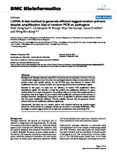
Cost functions of subtrees rooted at v1 , v2 and v3 in Figure 1, with IQ threshold IT = 5 and number of discretization levels φ = 5.
B. Histogram-Based Representation In our baseline histogram representation, the y-axis is the cost (total number of transmissions along routing path) and the x-axis is the IQ that can be accumulated with the given cost. Depending on the routing path that is taken, different IQ values may be accumulated for a given cost. In this baseline representation, the accumulated IQ is the largest possible for a particular cost. Note that the computation of this maximum IQ for a given cost is similar to the original routing problem (which finds the minimum cost of obtaining a particular IQ value), and cannot be computed efficiently for a large network. An exhaustive search can be used to compute the maximum IQ values for each cost in the small network in Figure 1. The solid lines (labeled as baseline) in Figure 2 illustrate baseline curves for cost vs maximum IQ, for each upstream node of v0 . As highlighted previously, such a baseline representation embeds detailed network topology and IQ distribution information, at the cost of excessive computational and communication overheads. To reduce information content and overheads of the representations, quantization levels are introduced. 1) Quantization: Let φ be the number of quantization levels in the baseline representation. This results in φ histograms, each of width IφT , where IT is the IQ threshold required for PoI detection. The range of IQ values represented by the ith block (i = 1, ..., φ) is (i − 1) · IφT to i · IφT (inclusive). The number of data points that fall within the range of IQ values governed by the ith block of the histogram is denoted as ni . The corresponding cost ci for the ith block is ci = �j=i j=1 nj . It can be deduced that with a cost of ci + 1, the maximum IQ obtainable is at least i · IφT . The dotted lines (labeled as histogram) in Figure 2 illustrate the relationship between the baseline and histogram representations from the perspectives of nodes v1 , v2 and v3 in Figure 1. 2) IQ Estimation: After quantization, the (original) baseline representation of the IQ that is known to an arbitrary node ve is substituted by a (compact) histogram representation, to be transmitted to its downstream node vd . We now discuss how vd estimates the IQ of the subtree rooted at ve , based on the histogram representation it receives from ve . Each of the ni points in the ith block of the histogram is associated with cost cki = ci − ni + k, where 1 ≤ k ≤ ni . Assuming that each of these points is uniformly distributed
TABLE I E STIMATED AND ACTUAL IQ GAIN PER INCREMENTAL COST c. v1
v2
v3
Cost c
q1 (c)
qˆ1 (c)
q2 (c)
qˆ2 (c)
q3 (c)
qˆ3 (c)
1
0.3
0.3
0.4
0.4
1.2
1.2
2
0.4
0.65
1.4
1.4
1.8
1.6
3
2.1
2.1
1.9
1.9
2.2
2.2
4
-
-
2.7
2.7
-
-
5
-
-
3
2.9
-
-
6
-
-
3.2
3.2
-
-
within the block range, the corresponding estimated IQ qˆe (cki ) obtained with a cost of cki (from the perspective of vd ) is: qˆe (cki ) =
k IT [(i − 1) + ]. φ ni + 1
(12)
Given the IQ qe obtainable from the upstream node ve and the maximum IQ qeM that can be obtained using the subtree rooted at ve , the estimated IQ in Equation (12) can be further tightened by using qe and qeM as the lower and upper bounds of the histogram. Note that ci and qˆe (cki ) are undefined ∀ i = �qeM · IφT as these are not regions of interest. The dotted lines with points (labeled estimation) in Figure 2 plot the values of estimated IQ qˆe (c) for each additional edge from the subtree rooted at ve , from the perspective of its downstream node vd . The estimation plot can be interpreted in this way: For a cost of c, it is likely that at least an IQ of qˆe (c) can be obtained. Table I lists the baseline qe (c) and estimated qˆe (c) values for each of the subtrees rooted at the upstream nodes of v0 in Figure 1. Note that qe (c) can be larger or smaller than qˆe (c). Finally, we discuss the selection of the parameter φ. In our IQ estimations, each of the ni points in the ith block is assumed to be uniformly distributed; the corresponding IQ estimations for each of the points is also uniformly distributed. If this assumption is valid, then the value of φ can be small. However, if IQ values vary significantly among nodes, then a larger φ value is required to increase the accuracy of the piecewise linear approximation. We can now describe our proposed IQ-aware routing protocol in the following section.
This full text paper was peer reviewed at the direction of IEEE Communications Society subject matter experts for publication in the IEEE INFOCOM 2010 proceedings This paper was presented as part of the main Technical Program at IEEE INFOCOM 2010.
Algorithm 1 IQ Approximation Algorithm in Phase 2 1: Input: IT , qˆj (cj ) ∀vj ∈ Viu , 1 ≤ cj ≤ CjM 2: Variable: Itotal = 0, c¯j = 0 ∀vj 3: Output: qˆi (ci ) 1 ≤ ci ≤ CiM � � 4: while c¯j < CjM OR Itotal < IT do 5: k ← argmax [qˆj (c¯j + 1) − qˆj (c¯j )]
v0
v0
I3 =1.5
v3
I3 =1.5 0.4
1.2 0.6
Itotal = 1.2+0.6 =1.8 > 1.5
v7 v8
v3
I7 =0
0.4
v7
0.6
v8
1.2
I8=0.6
j
c¯k ← c¯k + 1 7: Itotal � ← Itotal + [qˆj (c¯j + 1) − qˆj (c¯j )] 8: qˆi ( c¯j ) ← Itotal 9: end while 6:
V. IQ-AWARE ROUTING P ROTOCOL In an event-driven WSN, data generated by a sensor provides information about the likelihood that a PoI has occurred. Section III describes how this data is mapped to the IQ qa provided by an activated node va . To minimize the cost of data transmission, activated nodes first generate hints that are aggregated towards the fusion center v0 so that a minimum cost detection tree can be constructed. The minimum IQ IT required to detect the PoI is assumed to be known. Upon activation, each node vj transmits hints to its downstream node vi in the form of a quadruple comprising: 1) information quality qj of vj ; 2) maximum information quality qjM that can be obtained using the subtree rooted at vj ; 3) maximum cost CjM of the subtree rooted at vj ; and 4) histogram {n1j , n2j , ..., nφj } representing the topologyaware IQ obtainable using the subtree rooted at vj . A. Initialization A distance-based aggregation tree is constructed using a shortest-path algorithm during network initialization. To maximize aggregation opportunities, data generated by an activated node is transmitted only after a delay that is inversely proportional to its distance from v0 . As an activated leaf node (without activated upstream nodes) has only one data point, building the histogram is trivial using the method in Section IV-B. Non-leaf nodes can have multiple upstream nodes. B. Aggregation and Update The histogram at node vi is updated in three main phases. • In Phase 1, vi estimates the IQ qˆj (cj ) that can be obtained for each cost 1 ≤ cj ≤ CjM , using the subtree rooted at each upstream node vj ∈ Viu . • Phase 2 is triggered if vi has multiple (activated) upstream nodes. A greedy heuristic is used to approximate the � maxCjM . imum IQ obtainable for each given cost 1 ≤ ci ≤ • In Phase 3, vi incorporates its cost and IQ qi into the IQ estimations obtained in earlier phase(s), and translates these estimations back into a (new) histogram for transmission to its downstream node. We now detail each of these phases, using numerical examples from the topology in Figure 1, with IT = 5 and φ = 5.
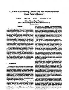
(a) v3 includes v8 into the (b) v3 assigns the appropriate IQ pruned tree and updates Itotal . thresholds to its upstream nodes. Fig. 3.
Sequence of pruning activities for subtree rooted at v3 .
1) Phase 1: Estimation of the IQ qˆj (cj ) for the subtree rooted at each upstream node vj is done by utilizing the histogram which is part of the quadruple transmitted from vj to vi . Considering the subtree rooted at v3 , the quadruples transmitted by v7 and v8 to v3 are {0.4, 0.4, 1, {1, ∅, ∅, ∅, ∅}} and {0.6, 0.6, 1, {1, ∅, ∅, ∅, ∅}} respectively. v3 then estimates the information quality qˆ7 (c7 ) ∀1 ≤ c7 ≤ C7M and qˆ8 (c8 ) ∀1 ≤ c8 ≤ C8M using Equation (12). Since v7 and v8 are both activated leaf nodes, v3 can easily and accurately estimate qˆ7 (1) = 0.4 and qˆ8 (1) = 0.6. 2) Phase 2: From a global perspective, it is trivial to see that with a cost of 1, only v3 is included in the routing path. Similarly, with a cost of 3, all the three nodes (v3 , v7 and v8 ) in the subtree rooted at v3 are included. However, with a cost of 2, either v7 or v8 is included, with the latter yielding a higher cumulative IQ. The general complexity � ofMcomputing Cj using an the highest IQ for each cost 1�≤ ci ≤ exhaustive brute-force search is vj ∈V u CjM . i We approximate the maximum IQ for each cost using a greedy heuristic that significantly reduces computational complexity while maintaining reasonable IQ accuracy. Let Itotal be the estimated cumulative IQ of all sensors that are included in the minimum cost tree Mi (initially empty). Recall that vi has computed qˆj (cj ) for each incremental cost 1 ≤ cj ≤ CjM along each subtree rooted at vj ∈ Viu in Phase 1. Let c¯j denote the current cost of the subtree rooted at vj , that has been included in Mi ; initially, c¯j = 0 ∀vj . At each iterative step, the estimated IQ qˆk (c¯k + 1) that provides the maximum IQ gain to Itotal is included in Mi . The IQ gain is computed by qˆk (c¯k + 1) − qˆk (c¯k ). This process repeats until: (i) all the subtrees rooted at the upstream nodes have been added to Mi ; or (ii) Itotal exceeds the IQ threshold IT . Based on the subtree rooted at v3 (and excluding itself) in Figure 1, the estimated maximum IQ values for the different costs using this greedy heuristic, are qˆ3 (1) = 0.6 and qˆ3 (2) = 0.6 + 0.4 = 1.0. Algorithm 1 summarizes the IQ approximation procedure that is executed by vi in Phase 2. 3) Phase 3: In the final step of the algorithm, the estimated maximum IQ obtained for the subtree rooted at vi is updated to include its own cost and IQ qi . The values of qˆ3 (ci ), where 1 ≤ ci ≤ CiM are updated such that qˆ3 (1) = 1.2, qˆ3 (2) = 1.2 + 0.6 = 1.8 and qˆ3 (3) = 1.2 + 1.0 = 2.2. Based on this updated set of IQ estimations, a new quantized histogram is constructed and forwarded to the downstream node v0 .
This full text paper was peer reviewed at the direction of IEEE Communications Society subject matter experts for publication in the IEEE INFOCOM 2010 proceedings This paper was presented as part of the main Technical Program at IEEE INFOCOM 2010.
C. Pruning The pruning phase commences after v0 receives data from its upstream nodes vj ∈ V0u . Its objective is to prune off as many nodes as possible from the initial distance-based aggregation tree, such that: (i) IQ constraint IT is still satisfied; and (ii) total transmission cost of collecting data from the resulting pruned tree is minimized. Hence, v0 has to allocate an M IQ threshold Ij (with corresponding estimated � cost cˆj ≤ Cj ) Ij ≥ IT ; (ii) to each upstream node � vj such that: (i) qˆj (cˆj ) ≥ Ij ; and (iii) cˆj is minimized. The pruning algorithm adopts a greedy approach similar to that in Phase 2 of the data aggregation algorithm. Based on previous computations, each node vi has the estimated maximum IQ qˆj (cj ) of all its upstream nodes vj ∈ Viu for each cost 1 ≤ cj ≤ CjM . The pruned routing tree is initially empty with total IQ Itotal = 0. vi iteratively includes into its pruned tree, the value of qˆj (cj ) that provides maximum IQ increment. This process repeats at vi until: (i) subtree rooted at each upstream node vj is included in the pruned tree; or (ii) aggregated IQ Itotal of the pruned tree exceeds the IQ threshold Ii at vi . The expected output of the pruning algorithm at vi is the assignment of Ij to each upstream node vj . The pruning algorithm is executed recursively at each upstream node vj along the initial aggregation tree using Ij . An activated node vj with assigned IQ threshold Ij = 0 is considered to be pruned off and not required to be part of the resulting pruned tree. Pruned nodes suppress their data for a time epoch before resuming the forwarding of data towards v0 . The temporary suppression of data enables the aggregation routing path to be adaptive towards dynamic changes in the network and PoI, while reducing transmission costs. Assuming that v0 has assigned I3 = 1.5 in Figure 1, we look at how v3 assigns I7 and I8 to its upstream nodes v7 and v8 . Since qˆ8 (1) > qˆ7 (1), the former is included into the pruned tree of v3 and Itotal = q3 + qˆ8 (1) = 1.2 + 0.6 = 1.8 > 1.5 = I3 , as in Figure 3(a). Since the IQ threshold at v3 is met, the pruning algorithm at v3 terminates with I7 = 0 and I8 = 0.6, as shown in Figure 3(b). D. Discussion The advantage of the proposed aggregation scheme is that while the fusion center sees a highly aggregated summary of how IQ is distributed in the WSN, the accuracy improves in the pruning process when specific subtrees are selected. Hence, one can think of the aggregation process as building a distributed structure that allows IQ distribution information to be selective refined as needed by the pruning process. Finally, each sensor node has a low but non-zero probability of false positive event detection. If the network is sufficiently large, aggregation of a large number of sensors that falsely detect an event may be sufficient to trigger event detection. Such false alarms can be handled by the fusion center using simple heuristics: Since sensors with false positives are randomly distributed, the cost for event detection is very large as compared to that of normal event detection; hence, a simple cost threshold may be used to suppress such false positives.
VI. P ERFORMANCE E VALUATION We evaluate the performance of IQAR in Qualnet 4.0 [28] and compare against the following routing protocols: 1) aggTree: Distance-based aggregation tree that collects data from all activated sensors, to be processed at v0 . 2) walk: IQ-aware routing protocol that routes data greedily towards next hop with highest IQ. When no IQ can be further gained from neighbors of the transmitter, or when aggregated data has sufficient IQ, data is routed back to v0 using a shortest path algorithm. Routing process is initiated from node with highest global IQ among all activated nodes, and there is only one ongoing transmission (and routing path) at any time. 3) brute-force: IQ-aware routing protocol that is similar in operations to IQAR, but uses an exhaustive bruteforce search to compute the maximum IQ for each cost function during data aggregation and pruning. The fusion center v0 is located near the bottom left hand corner of the terrain of size {100m×100m}. All the other sensors are uniform-randomly distributed in the network. An exponential sensing model [29] is used for function f (ri ) in Equation (1). The performance result illustrated is averaged over the sensing interval (1 second), and 20 seed runs. The target detection and false alarm probabilities are Pd = 0.9 and Pf = 0.001 respectively, and the transmission range is ≈ 8m. A. Varying Local Information Quality The per-sample false alarm probability p0 is increased in Figure 4, which leads to: (i) increase in number of activated nodes and detection region; and (ii) decrease in local IQ of each node. The PoI occurs at a fixed location {80m × 80m} and the network has 250 nodes. The aggregation cost in Figure 4(a) measures number of transmissions required to collect data from fused nodes, and is highly correlated to the number of fused nodes. Due to the lowered per-node IQ as p0 increases, more sensory data have to be aggregated to meet the IQ threshold IT , resulting in increased aggregation cost for all protocols . aggTree incurs the highest aggregation cost as it fuses data from all the activated nodes. In contrast, the three IQ-aware protocols - walk, bruteforce and IQAR - aggregate data from only a subset of the activated nodes and incur less aggregation costs. The forwarding cost in Figure 4(b) measures number of transmissions required to forward data from the last aggregated node to v0 , and is dependent on activated node locations as well as PoI location. The enlarged detection region resulting from the increase in p0 leads to a corresponding increase in forwarding cost, especially for aggTree as it collects data from all the activated nodes. IQAR incurs higher costs than brute-force as the former adopts a greedy approach that may not yield the best routing path for a given IQ threshold. The gradual decrease in forwarding cost observed for all the protocols as p0 increases is due to the activation of more sensor nodes that are nearer to v0 , which decreases the distance between v0 and first aggregated node along each routing path.
This full text paper was peer reviewed at the direction of IEEE Communications Society subject matter experts for publication in the IEEE INFOCOM 2010 proceedings This paper was presented as part of the main Technical Program at IEEE INFOCOM 2010.
25
40
10 5
0.15 0.25 0.35 false alarm probability p0
0 0.05
0.45
(a) Aggregation cost. Fig. 4.
aggTree walk brute-force IQAR
delay
cost
120
80
40
0 200
0.15 0.25 0.35 false alarm probability p0
300 no. of nodes
350
400
(a) Total cost. Fig. 5.
0.15 0.25 0.35 false alarm probability p0
8 0.05
0.45
(c) Total cost.
0.45
(d) Delay.
18
120
30
16
100
24
aggTree walk brute-force IQAR
14 12
8 200
0.15 0.25 0.35 false alarm probability p0
Performance with increasing per-sample false alarm probability p0 .
80
aggTree walk brute-force IQAR
60 40
0 250
300 no. of nodes
350
400
(b) Delay
Performance with increasing network density.
B. Varying Network Density In Figure 5, network size increases from 200 to 400 nodes and PoI is located at {80m×80m} with p0 = 0.35. Due to the increase in network size (and density), the number of activated nodes increase. The total cost incurred by aggTree increases correspondingly in Figure 5(a) as it collects data from all activated nodes. The remaining three IQ-aware protocols do not collect data from all the activated nodes and can achieve lower costs. The excessive delays incurred by walk in Figure 5(b) highlights the caveat of having only a single routing path that limits parallelism of data aggregation and forwarding. C. Varying Distance between Event (PoI) and Fusion Center We vary the distance between the PoI and fusion center v0 in a network of 250 nodes with p0 = 0.35 in Figure 6. The x/y coordinates of the PoI are varied from 40m to 80m1 . As distance to event increases, it is located nearer to edges of the terrain, leading to decrease in number of activated nodes. Consequently, the number of fused nodes and aggregation distance of 60 to the PoI implies that the PoI is located at {60m×60m}.
aggTree walk brute-force IQAR
18 12 6
20
Figure 4(c) illustrates the total cost of aggregating and forwarding data packets to v0 . Since aggregation cost dominates over forwarding cost in a network with a small network diameter, the total cost has a similar trend to aggregation cost. The delay incurred in Figure 4(d) is measured in terms of number of (sequential) transmissions. Despite the low transmission cost incurred by walk, it incurs the highest delay as transmissions occur sequentially along a single path, where aggregation occurs strictly before forwarding. Due to the presence of multiple paths in brute-force and IQAR, multiple aggregation and forwarding of data can take place simultaneously, thus reducing the overall delays.
1A
12
0 0.05
0.45
10
250
80
(b) Forwarding cost.
160
16
120
40
aggregation cost
0 0.05
aggTree walk brute-force IQAR
delay
15
20 aggTree walk brute-force IQAR
160
aggTree walk brute-force IQAR
forwarding cost
80
200
20
cost
aggTree walk brute-force IQAR
120
forwarding cost
aggregation cost
160
0 40
50
60 70 distance to event
80
(a) Aggregation cost. Fig. 6.
40
50
60 70 distance to event
80
(b) Forwarding cost.
Performance with increasing distance to event (PoI).
cost using aggTree decreases in Figure 6(a). Forwarding cost generally increases with increasing distance to PoI in Figure 6(b), as more transmissions are required to forward data from activated sensors to v0 . IQAR uses a greedy heuristic to estimate IQ contributions of nodes; hence it incurs higher forwarding cost than brute-force. Despite the low aggregation cost incurred by walk, it incurs relatively higher forwarding costs as the activated sensor with the highest global IQ may be further away from v0 than other activated nodes. D. Varying Suppression Interval In the above scenarios, the PoI is statically located throughout the monitoring period. Both brute-force and IQAR can achieve significant cost and delay savings over aggTree as they aggregate data from only a subset of activated nodes to satisfy the IQ threshold. Data from the remaining activated nodes are suppressed for a suppression interval to reduce transmission costs2 . However, one main concern with such protocols (which utilize data suppression to reduce costs) is whether a mobile PoI can be detected with sufficient IQ. In Figure 7, the speed of the PoI is fixed at 2.5 ms−1 in a network of 250 nodes with p0 = 0.35. As suppression interval increases from 2s to 10s, the amount of aggregated data decreases as nodes are suppressed for longer periods of time. Subsequently, there is a decrease in total cost and delay of brute-force and IQAR in Figures 7(a) and 7(b). However, it should be noted that due to the suppression of data, the detection accuracies achieved by these two protocols deteriorate by 5% to 10% with mobile PoIs. The total cost and delay incurred by aggTree and walk remain constant as they do not suppress data. 2 With a suppression interval of x seconds, an activated node suppresses its data for at least x seconds after its last transmission.
This full text paper was peer reviewed at the direction of IEEE Communications Society subject matter experts for publication in the IEEE INFOCOM 2010 proceedings This paper was presented as part of the main Technical Program at IEEE INFOCOM 2010.
15
120
14
100
aggTree walk brute-force IQAR
80 60
delay
cost
100 aggTree walk brute-force IQAR
13 12
40 11
20 0 4 6 8 suppression delay (s)
10
aggTree walk brute-force IQAR
60 40
0 2
(a) Total cost. Fig. 7.
80
aggTree walk brute-force IQAR
15
10
5
20
10 2
20
forwarding cost
120
aggregation cost
140
4 6 8 suppression delay (s)
10
(b) Delay
0 0
0.5
1
1.5 2 2.5 speed (m/s)
(a) Aggregation cost.
Performance with varying suppression interval (delay).
Fig. 8.
E. Varying Event Mobility −1
In Figure 8, the PoI moves with varying speeds from 0 ms to 3.5 ms−1 diagonally across the network with 250 nodes and p0 = 0.35. The suppression interval is fixed at 5 seconds. As event mobility increases, forwarding cost in Figure 8(b) increases as the PoI is located increasingly further away from v0 . As the PoI also exits the suppression region more quickly with higher event mobility, more sensors are activated, leading to the increased aggregation cost incurred by brute-force and IQAR in Figure 8(a). Since the PoI moves diagonally across the network, it is much closer to the network edge at higher mobilities, which limits the number of activated nodes. Hence, the aggregation costs incurred by aggTree, IQAR and bruteforce drop slightly when speed exceeds 2 ms−1 . VII. C ONCLUSION In this work, we propose IQAR - an Information Quality Aware Routing protocol for event-driven sensor networks. IQAR considers the individual IQ contribution of each sensory data, and collects only sufficient data for a phenomenon of interest (PoI) to be detected reliably. Redundant data is suppressed for a time interval to reduce traffic load and alleviate medium access contention. This allows IQAR to achieve significant energy and delay savings while maintaining information quality in event detection. ACKNOWLEDGMENT This work is done under the USCAM-CQ project which is part of the UWB-Sentient Computing Research Programme funded by SERC, A*STAR Singapore. R EFERENCES [1] T. Q. S. Quek, D. Dardari, and M. Z. Win, “Energy Efficiency of Dense Wireless Sensor Networks: To Cooperate or Not to Cooperate,” JSAC, vol. 25, no. 2, 2007. [2] I. F. Akyildiz, W. Su, Y. Sankarasubramaniam, and E. Cayirci, “Wireless Sensor Networks: A Survey,” Computer Networks, vol. 38, no. 4, 2002. [3] H. Zhang, A. Arora, Y. Choi, and M. G. Gouda, “Reliable Bursty Convergecast in Wireless Sensor Networks,” in MobiHoc, 2005. [4] B. Krishnamachari, D. Estrin, and S. Wicker, “Modeling Data-Centric Routing in Wireless Sensor Networks,” in INFOCOM, 2002. [5] L. Yu and A. Ephremides, “Detection Performance and Energy Efficiency Trade-off in a Sensor Network,” in Allerton Conference on Communication, Control, and Computing, 2003. [6] R. M. Karp, “Reducibility Among Combinatorial Problems,” in Symposium on the Complexity of Computer Computations, 1972. [7] K. W. Fan, S. Liu, and P. Sinha, “Scalable Data Aggregation for Dynamic Events in Sensor Networks,” in SenSys, 2006.
3
3.5
0
0.5
1
1.5 2 2.5 speed (m/s)
3
3.5
(b) Forwarding cost.
Performance with varying event (PoI) mobility.
[8] M. C. Vuran, O. B. Akan, and I. F. Akyildiz, “Spatio-Temporal Correlation: Theory and Applications for Wireless Sensor Networks,” Computer Networks, vol. 45, no. 3, 2004. [9] K. W. Fan, S. Liu, and P. Sinha, “On the Potential of Structure-Free Data Aggregation in Sensor Networks,” in INFOCOM, 2006. [10] H. Luo, Y. Liu, and S. K. Das, “Routing Correlated Data with Fusion Cost in Wireless Sensor Networks,” TMC, vol. 5, no. 11, 2006. [11] C. Intanagonwiwat, D. Estrin, R. Govindan, and J. Heidemann, “Impact of Network Density on Data Aggregation in Wireless Sensor Networks,” in ICDCS, 2002. [12] A. Goel and D. Estrin, “Simultaneous Optimization for Concave Costs: Single Sink Aggregation or Single Source Buy-at-Bulk,” in Annual ACM-SIAM Symposium on Discrete Algorithms, 2004. [13] W. Zhang and G. Cao, “Optimizing Tree Reconfiguration for Mobile Target Tracking in Sensor Networks,” in INFOCOM, 2004. [14] ——, “DCTC: Dynamic Convoy Tree-based Collaboration for Target Tracking in Sensor Networks,” Transactions on Wireless Communications, vol. 3, no. 5, 2004. [15] W. R. Heinzelman, A. Chandrakasan, and H. Balakrishnan, “An Application-Specific Protocol Architecture for Wireless Microsensor Networks,” Transactions in Wireless Communications, vol. 1, no. 4, 2002. [16] S. Lindsey and C. S. Raghavendra, “PEGASIS: Power-Efficient Gathering in Sensor Information Systems,” in Aerospace Conference, 2002. [17] S. Pattem, B. Krishnamachari, and R. Govindan, “The Impact of Spatial Correlation on Routing with Compression in Wireless Sensor Networks,” in IPSN, 2004. [18] M. Chu, H. Haussecker, and F. Zhao, “Scalable Information-Driven Sensor Querying and Routing for Ad Hoc Heterogenous Sensor Networks,” IJHPCA, vol. 16, no. 3, 2002. [19] F. Zhao, J. Liu, J. Liu, L. Guibas, and J. Reich, “Collaborative Signal and Information Processing: An Information-Directed Approach,” Proceedings of the IEEE, vol. 91, no. 8, 2003. [20] J. Liu, F. Zhao, and D. Petrovic, “Information-Directed Routing in Ad Hoc Sensor Networks,” JSAC, vol. 23, no. 4, 2005. [21] L. Yu, L. Yuan, G. Qu, and A. Ephremides, “Energy-Driven Detection Scheme with Guaranteed Accuracy,” in IPSN, 2006. [22] L. Yu and A. Ephremides, “Detection Performance and Energy Efficiency of Sequential Detection in a Sensor Network,” in HICSS, 2006. [23] W. P. Tay, J. N. Tsitsiklis, and M. Z. Win, “Detection in Dense Wireless Sensor Networks,” in WCNC, 2007. [24] A. Wald, “Sequential Tests of Statistical Hypotheses,” Annals of Mathematical Statistics, vol. 16, no. 2, 1945. [25] R. Viswanathan and P. K. Varshney, “Distributed Detection With Multiple Sensors: Part I - Fundamentals,” Proceedings of the IEEE, vol. 85, no. 1, 1997. [26] S. C. A. Thomopoulos, R. Viswanathan, and D. K. Bougoulias, “Optimal Distributed Decision Fusion,” Transactions on Aerospace and Electronic Systems, vol. 25, no. 5, 1989. [27] H. X. Tan, M. C. Chan, W. Xiao, P. Y. Kong, and C. K. Tham, “Information Quality Aware Routing in Event-Driven Sensor Networks,” School of Computing, National University of Singapore, Tech. Rep., 2009, http://www.comp.nus.edu.sg/∼tanhweex/research/iqar 2009.pdf. [28] Qualnet Network Simulator, Scalable Network Technologies, Inc. [Online]. Available: www.qualnet.com [29] K. Chakrabarty and Y. Zou, “A Distributed Coverage- and ConnectivityCentric Technique for Selecting Active Nodes in Wireless Sensor Networks,” Transactions on Computers, vol. 54, no. 8, 2005.