IEEE TRANSACTIONS ON EDUCATION, VOL. 53, NO. 3, AUGUST 2010
349
Integrating Asynchronous Digital Design Into the Computer Engineering Curriculum Scott C. Smith, Senior Member, IEEE, Waleed K. Al-Assadi, Senior Member, IEEE, and Jia Di, Member, IEEE
Abstract—As demand increases for circuits with higher performance, higher complexity, and decreased feature size, asynchronous (clockless) paradigms will become more widely used in the semiconductor industry, as evidenced by the International Technology Roadmap for Semiconductors’ (ITRS) prediction of a likely shift from synchronous to asynchronous design styles in order to increase circuit robustness, decrease power, and alleviate many clock-related issues [1], [2]. ITRS shows that asynchronous circuits accounted for 11% of chip area in 2008, compared to 7% in 2007, and estimates they will account for 23% of chip area by 2014 and 35% of chip area by 2019 [3]. To meet this growing industry need, computer engineering students should be introduced to asynchronous circuit design to make them more marketable and more prepared for the challenges faced by the digital design community for years to come. This paper introduces asynchronous logic design in the context of the familiar synchronous logic, then provides a description of course modules developed for NULL Convention Logic (NCL), an asynchronous logic paradigm that is very similar to the synchronous paradigm. This approach ensures that students can easily relate asynchronous design and optimization techniques to the corresponding synchronous techniques. The materials presented in this paper have been used in a number of undergraduate and graduate courses and have been well received by the students. Index Terms—Asynchronous logic, dual-rail design, input-completeness, NULL Convention Logic (NCL), observability, pipelining, quad-rail design.
I. INTRODUCTION HE development of synchronous circuits currently dominates the multibillion-dollar semiconductor design industry. However, there are major limiting factors to the synchronous, clocked approach, including the increasing difficulty of clock distribution, increasing clock rates, decreasing feature size, increasing power consumption, timing closure effort, and difficulty with design reuse. Asynchronous circuits require less power, generate less noise, produce less electromagnetic interference (EMI), and allow for easier reuse of components, compared to their synchronous counterparts, without compromising performance. However, there are drawbacks, including
T
Manuscript received August 06, 2008; revised April 06, 2009. First published September 09, 2009; current version published August 04, 2010. This work was supported by the National Science Foundation under CCLI Grants DUE-0536343, DUE-0717572, and DUE-0717767. S. C. Smith is with the Department of Electrical Engineering, University of Arkansas, Fayetteville, AR 72701 USA (e-mail:
[email protected]). W. K. Al-Assadi is with the Department of Electrical and Computer Engineering, Missouri University of Science & Technology, Rolla, MO 65409 USA (e-mail:
[email protected]). J. Di is with the Department of Computer Science and Computer Engineering, University of Arkansas, Fayetteville, AR 72701 USA (e-mail:
[email protected]). Digital Object Identifier 10.1109/TE.2009.2021391
increased area and little computer-aided design (CAD) tool support. In most computer engineering curricula, students are only taught the synchronous, clocked paradigm and never even touch on asynchronous digital design. Those curricula that do mention asynchronous design do so only in passing; the students are not taught how to design asynchronous circuits. The widespread introduction of asynchronous digital design in the classroom is largely constrained by the lack of introductory educational materials. Some textbooks (e.g., [4] and [5]) contain a chapter on asynchronous circuit design; however, this material is outdated, does not at all reflect the asynchronous techniques being used in the industry today, and is therefore rarely taught. There are a few U.S. universities that currently offer asynchronous digital design in their curriculum [6]–[8]. Of these courses, one is a special topics class that was last offered in 1998, and the other two are primarily for graduate students. Furthermore, asynchronous digital design should not be limited to a single course on the subject; instead, it should be integrated into a number of courses such that students have a better chance of being exposed to the subject and of understanding this material in the context of more traditional design approaches. This paper substantially adds to the educational literature on asynchronous logic design, building on the previous work [9], presents one approach for integrating asynchronous circuit design into the computer engineering curriculum, and provides case studies of three courses at two universities. The paper is organized into five sections. Section II presents an overview of asynchronous logic. Section III describes the asynchronous materials developed for use in computer engineering courses. Section IV describes the case studies, outlining how the courses have been augmented to include the asynchronous materials, and presents the results of the course offerings. Section V provides conclusions and directions for future work. II. OVERVIEW OF ASYNCHRONOUS LOGIC Asynchronous circuits can be grouped into two main categories: bounded-delay and delay-insensitive models. Boundeddelay models such as micropipelines [10] assume that delays in both gates and wires are bounded. Delay elements are added based on worse-case scenarios to avoid hazard conditions. This approach requires extensive timing analysis of worse-case behavior to ensure correct circuit operation. On the other hand, delay-insensitive (DI) circuits assume delays in both logic elements and interconnects to be unbounded. They do assume, though, that wire forks within basic components, such as a full adder, are isochronic [11], [12], meaning that the wire delays
0018-9359/$26.00 © 2009 IEEE
350
IEEE TRANSACTIONS ON EDUCATION, VOL. 53, NO. 3, AUGUST 2010
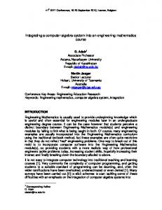
Fig. 1. NCL system framework: Input wavefronts are controlled by local handshaking signals and completion detection instead of by a global clock signal. Feedback requires at least three DI registers in the feedback loop to prevent deadlock [25].
within a component are much less than the logic element delays within the component, which is a valid assumption even in future nanometer technologies. Wires connecting components do not need to adhere to the isochronic fork assumption. This implies the ability to operate in the presence of indefinite arrival times for the reception of inputs. Completion detection of the output signals allows for handshaking to control input wavefronts. DI design styles therefore require very little, if any, timing analysis to ensure correct operation (i.e., they are correct by construction), and they also yield average-case performance rather than the worse-case performance of bounded-delay and synchronous paradigms [13]. A. Delay-Insensitive Circuits Most DI methods combine state-holding C-elements [14] with Boolean gates for circuit construction. A C-element behaves as follows: When all inputs assume the same value, then the output assumes this value; otherwise, the output does not change. Seitz’s [15], DIMS [16], Anantharaman’s [17], Singh’s [18], and David’s [19] methods are examples of DI paradigms that use only C-elements to achieve delay-insensitivity. Other paradigms such as phased logic [20] and NULL Convention Logic (NCL) [21] target a library of multiple gates with hysteresis state-holding functionality. Phased logic converts a traditional synchronous gate-level circuit into a DI circuit by replacing each conventional synchronous gate with its corresponding phased logic gate, then augmenting the new network with additional handshaking signals [20]. NCL functions are realized using 27 fundamental gates implementing the set of all functions of four or fewer variables, each with hysteresis state-holding functionality [22]. Seitz’s method, Anantharaman’s approach, and DIMS require the generation of all minterms to implement a function, where a minterm is defined as the logical AND, or product, containing all input signals in either complemented or noncomplemented form. While Singh’s and David’s methods do not require full minterm generation, they rely solely on C-elements for speed-independence. NCL also does not require full minterm generation and, furthermore, includes 27 fundamental state-holding gates for circuit design, rather than only C-elements, thus yielding a greater potential for optimization than other delay-insensitive paradigms [23]. Phased logic does not require full minterm generation and does not rely solely on C-elements for speed-independence; however, phased logic circuitry is derived directly from its equivalent synchronous design, not created independently, thus it does not have the same potential for optimization as does NCL. Furthermore, the
phased logic paradigm has been developed mainly for easing the timing constraints of synchronous designs, not for obtaining speed and power benefits [20], whereas these are main concerns of other asynchronous paradigms. Self-timed circuits can also be designed at the transistor level as demonstrated by Martin [24]. However, automation of this method would be vastly different than that of the standard synchronous approach since it optimizes designs at the transistor level instead of targeting a predefined set of gates, as do the previously mentioned DI methods. Overall, NCL offers the best opportunity for integrating asynchronous digital design into the predominantly synchronous semiconductor design industry for the following reasons. 1) The framework for NCL systems consist of DI combinational logic sandwiched between DI registers, as shown in Fig. 1. This framework is very similar to synchronous systems, such that the automated design of NCL circuits can follow the same fundamental steps as synchronous circuit design automation. This similarity will enable the developed DI design flow to be more easily incorporated into the chip design industry since the tools and design process will already be familiar to designers such that the learning curve will be relatively flat. 2) NCL systems are delay-insensitive, making the design process much easier to automate than other non-DI asynchronous paradigms since minimal delay analysis is necessary to ensure correct circuit operation. 3) NCL systems have power, noise, and EMI advantages compared to synchronous circuits; performance and design reuse advantages compared to synchronous and non-DI asynchronous paradigms; area and performance advantages compared to other gate-level DI paradigms; and a number of advantages for designing complex systems, like systems-on-chip (SoCs), including substantially reduced crosstalk between analog and digital circuits, ease of integrating multirate circuits, and facilitation of component reuse and technology migration.
B. NULL Convention Logic (NCL) NCL is a DI asynchronous paradigm, which means that NCL circuits will operate correctly regardless of when circuit inputs become available. Therefore, NCL circuits are said to be correct by construction (i.e., no timing analysis is necessary for correct operation). NCL circuits utilize dual-rail or quad-rail logic to achieve delay-insensitivity. A dual-rail signal, , consists of and , which may assume any value two wires or rails,
SMITH et al.: INTEGRATING ASYNCHRONOUS DIGITAL DESIGN INTO COMPUTER ENGINEERING CURRICULUM
TABLE I DUAL-RAIL SIGNAL
351
TABLE III 27 FUNDAMENTAL NCL GATES
TABLE II QUAD-RAIL SIGNAL
from the set , as depicted in Table I. The DATA0 state corresponds to a Boolean logic 0, the DATA1 state corresponds to a Boolean logic 1, and the NULL state corresponds to the empty set (meaning that the value of is not yet available). The two rails are mutually exclusive such that both rails can never be asserted simultaneously; this state is defined as an illegal state. A quad-rail signal, , consists of four wires, , and , which may assume any value from the set , as depicted in Table II. The DATA0 state corresponds to two Boolean logic and ; the DATA1 state signals, and , where and ; the DATA2 state correcorresponds to sponds to and ; the DATA3 state corresponds and ; and the NULL state corresponds to the to empty set, meaning that the result is not yet available. The four rails of a quad-rail NCL signal are mutually exclusive such that no two rails can ever be asserted simultaneously; these states are defined as illegal states. Both dual-rail and quad-rail signals are space-optimal, 1-hot, delay-insensitive codes, requiring two wires per bit. NCL circuits are comprised of 27 fundamental gates [23], as shown in Table III, which constitute the set of all functions consisting of four or fewer variables. Since each rail of an NCL signal is considered a separate variable, a four-variable function is not the same as a function of four literals, which would consist of eight variables for dual-rail logic (e.g., a literal includes both a variable and its complement, and , whereas NCL rails are never complemented, such that a dual-rail NCL signal consists of two variables, and , where is equivalent to ). The primary type of threshold gate, shown in Fig. 2, is . THmn gates have inputs. the THmn gate, where 1 At least of the inputs must be asserted before the output will become asserted. In a THmn gate, each of the inputs is connected to the rounded portion of the gate, the output emanates from the pointed end of the gate, and the gate’s threshold value, , is written inside of the gate. Another type of threshold gate is referred to as a weighted . Weighted threshold gate, denoted as , applied threshold gates have an integer value, . , where is the number of inputs, to is the gate’s threshold, and , each , are the , respectively. integer weights of inputs For example, consider the TH34W2 gate, whose
Fig. 2. THmn threshold gate.
Fig. 3. TH34w2. threshold gate: Z
= AB + AC + AD + BCD.
are labeled , and , shown in Fig. 3. The weight of is therefore 2. Since the gate’s threshold, , is input 3, this implies that in order for the output to be asserted, either , and must all be asserted, or input must be inputs asserted along with any other input, , or . All NCL gates are designed with hysteresis state-holding capability such that once the output is asserted, all inputs must be deasserted before the output will be deasserted. Hysteresis ensures a complete transition of inputs back to NULL before asserting the output associated with the next wavefront of input data. Therefore, a THnn gate is equivalent to an n-input C-element, and a TH1n gate is equivalent to an n-input OR gate. NCL threshold gates may also include a reset input to initialize the output. Circuit diagrams designate resettable gates by either a or an appearing inside the gate, along with the gate’s threshold.
352
IEEE TRANSACTIONS ON EDUCATION, VOL. 53, NO. 3, AUGUST 2010
Fig. 4. Single-bit dual-rail register.
Fig. 6. N-input completion component.
Fig. 5. Single-signal quad-rail register.
denotes the gate as being reset to logic 1; to logic 0. These resettable gates are used in the design of DI registers [25]. NCL systems require at least two DI registers, shown in Figs. 4 and 5—one at the input and one at the output. Two adjacent register stages interact through their request and and , respectively, to prevent the acknowledge signals, current DATA wavefront from overwriting the previous DATA wavefront, by ensuring that the two DATA wavefronts are always separated by a NULL wavefront. The acknowledge signals are combined in the completion detection circuitry, shown in Fig. 6, to produce the request signal(s) to the previous register stage, utilizing either the full-word or bit-wise completion strategy [25]. To ensure delay-insensitivity, NCL circuits must adhere to the following criteria: input-completeness [23] and observability [23]. Input-Completeness requires that all outputs of a combinational circuit may not transition from NULL to DATA until all inputs have transitioned from NULL to DATA and that all outputs of a combinational circuit may not transition from DATA to NULL until all inputs have transitioned from DATA to NULL. In circuits with multiple outputs, it is acceptable according to Seitz’s “weak conditions” of DI signaling [15] for some of the outputs to transition without having a complete input set present, as long as all outputs cannot transition before all inputs arrive.
Observability requires that no orphans may propagate through a gate. An orphan is defined as a wire that transitions during the current DATA wavefront, but is not used in the determination of the output. Orphans are caused by wire forks and can be neglected through the isochronic fork assumption (i.e., gate delays are much longer than wire delays within a component) [11], [12], as long as they are not allowed to cross a gate boundary. This observability condition, also referred to as indicatability or stability, ensures that every gate transition is observable at the output, which means every gate that transitions subsequently yields a transition of at least one of the outputs. Furthermore, when circuits utilize the bit-wise completion strategy with selective input-incomplete components, they must also adhere to the completion-completeness criterion [26], which requires that completion signals only be generated such that no two adjacent DATA wavefronts can interact within any combinational component. NCL systems consist of registration, combinational logic, and completion detection, connected together as shown in Fig. 1. NCL registration is realized through cascaded arrangements of single-bit dual-rail registers or single-signal quad-rail registers, depicted in Figs. 4 and 5, respectively. These registers consist of TH22 gates that pass a DATA value at the input only when is request for data (rfd) (i.e., logic 1), and likewise pass is request for null (rfn) (i.e., logic 0). They NULL only when , which is rfn when also contain a NOR gate to generate the register output is DATA and rfd when the register output is NULL. The registers shown below are reset to NULL since all TH22 gates are reset to logic 0. However, either register could be instead reset to a DATA value by replacing exactly one of the TH22n gates with a TH22d gate. single-bit dual-rail An N-bit register stage, comprised of NCL registers, requires completion signals, one for each bit. The NCL completion component, shown in Fig. 6, uses these lines to detect complete DATA and NULL sets at the
SMITH et al.: INTEGRATING ASYNCHRONOUS DIGITAL DESIGN INTO COMPUTER ENGINEERING CURRICULUM
353
Fig. 7. VHDL course schedule and changes.
output of every register stage and request the next NULL and DATA set, respectively. In full-word completion, the single-bit output of the completion component is connected to all lines of the previous register stage. Since the maximum input threshold gate is the TH44 gate, the number of logic levels in the completion component for an N-bit register is given by . Likewise, the completion component for an N-bit quad-rail registration stage requires inputs and can be realized in a similar fashion using TH44 gates. III. DEVELOPED MATERIALS To introduce asynchronous digital design effectively into the computer engineering curriculum, lecture notes and slides, example problems, group projects, and libraries of fundamental asynchronous gates and components have been developed. The educational materials were developed as Modules, such that portions of the materials could be easily integrated into a variety of courses as appropriate to meet the needs of a diverse set of courses with different learning objectives. A. Educational Modules The specific educational modules developed were the following. 1) Introduction to Asynchronous Logic: This includes a discussion of both bounded-delay and DI asynchronous paradigms, highlighting the differences between the two and comparing each to the synchronous, clocked paradigm. 2) Introduction to NULL Convention Logic (NCL): This includes a description of dual-rail and quad-rail signaling,
the 27 fundamental NCL gates, NCL registration, combinational logic, and completion detection components, and NCL DATA/NULL wavefront flow. 3) Transistor-level NCL Gate Design: This details the process for designing both static and semistatic NCL CMOS gates. 4) Input-Completeness and Observability: This explains the two criteria that must be followed when designing NCL circuits to ensure delay-insensitivity. 5) Dual-Rail NCL Design: This details the process for designing optimized dual-rail NCL combinational circuits. 6) Quad-Rail NCL Design: This details the process for designing optimized quad-rail NCL combinational circuits. 7) NCL Throughput Optimization: This describes the NCL throughput calculation, NCL pipelining, and the NULL cycle reduction optimization technique. 8) Group Projects: This contains a number of comprehensive group projects consisting of the implementation and testing of various types of NCL arithmetic circuits at various levels of abstraction. All of these course modules can be downloaded from the authors’ CCLI Web site: http://comp.uark.edu/~smithsco/ CCLI_async.html. Module 1 is similar to Sections II and II-A in this paper, although more extensive, and Module 2 is similar to Section II-B. Modules 1 and 2 are introductory and therefore do not contain any specific example problems or exercises; they are also independent of each other, such that a broad discussion of asynchronous logic in general is not required before discussing NCL specifics. Modules 3–7 all contain an explanation of the specific topic along with a comprehensive example and exercise problems. Modules 2 and 4 are prerequisites
354
IEEE TRANSACTIONS ON EDUCATION, VOL. 53, NO. 3, AUGUST 2010
Fig. 8. VLSI course schedule and changes.
for all subsequent modules, while Modules 3, 5, 6, and 7 are independent of each other. The comprehensive group projects in Module 8 require various other modules as prerequisites, depending on the specific project requirements and objectives.
Digital Design II, at University of Arkansas (UA) in Spring 2008. The revised VHDL and VLSI courses were taught for a second time in 2007.
B. Asynchronous Libraries
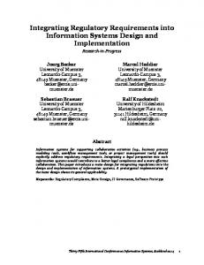
The original schedule for the VHDL course is shown on the left-hand side of Fig. 7. This schedule provides the students with approximately 13 weeks of topic lectures, leaving around 3 weeks for discussion of homework and project assignments and their solutions, holidays, and the midterm exam. Note that the final exam is given the week after the 16-week semester concludes. This schedule has been used by the primary author over the past five years and has been shown to work well. The course does require the students to do a sizable amount of work, but after its successful completion, they are well versed in VHDL. To integrate the asynchronous logic materials into the VHDL course, the last quarter of the original schedule was revised, as shown on the right-hand side of Fig. 7. The floating-point arithmetic and microprocessor architecture topics were replaced with the asynchronous topics. HW#5 on generic constants and generate statements was changed to instead cover Text I/O. HW#6 on the design of an IEEE single precision floating-point coprocessor was switched to an assignment on NCL. Design Project #2 on implementing a microcontroller in VHDL and Text I/O was replaced with the design of a complex generic NCL arithmetic circuit. These changes replace three weeks of topics with two and two-thirds weeks of asynchronous logic topics, providing an extra third of a week for additional explanation of the NCL assignments and solutions. Furthermore, these changes do not eliminate any key VHDL course material; both floating-point arithmetic and RISC microcontroller architecture are covered in various other computer engineering
In order to assist students with designing and testing NCL circuits at various levels of abstraction, static and semistatic NCL VHDL, transistor-level, and physical-level libraries have been created. The transistor-level and physical-level libraries of the fundamental NCL gates were implemented with the Mentor Graphics CAD tools using the 1.8-V, 0.18- m TSMC CMOS process, and the static library has subsequently been ported to the Cadence CAD tools using the 3.3-V, 0.5- m IBM 5AM BiCMOS process. The VHDL library consists of a package that defines the fundamental NCL dual-rail and quad-rail data types, a file containing the fundamental NCL gates, with delays based on the simulated physical-level 0.18- m static NCL gates, a file containing generic versions of standard NCL registration and completion components, and a package consisting of various functions to be used in testbenches. The VHDL, transistor-level, and physical-level NCL libraries can all be downloaded from the authors’ CCLI Web site: http://comp.uark.edu/~smithsco/ CCLI_async.html. IV. COURSE INTEGRATION AND ASSESSMENT The asynchronous modules and libraries were successfully incorporated into two senior/graduate-level elective courses at University of Missouri—Rolla, now Missouri University of Science & Technology (MST)— Digital System Modeling with VHDL and Introduction to VLSI, in Spring and Fall Semester 2006, respectively—and into a required undergraduate course,
A. VHDL Course
SMITH et al.: INTEGRATING ASYNCHRONOUS DIGITAL DESIGN INTO COMPUTER ENGINEERING CURRICULUM
355
Fig. 9. Digital Design II course schedule.
courses and were only discussed in the VHDL course so that they could be used as sample circuits to be designed in VHDL. Furthermore, since asynchronous circuits must be designed as structural models and cannot be described as behavioral or dataflow models and synthesized using industry-standard CAD tools, the topic fits seamlessly into the discussion of generate statements, which are mostly used for structural models. B. VLSI Course The schedule for the revised VLSI course is shown in Fig. 8. This schedule provides the students with approximately 14 weeks of topic lectures, leaving around two weeks for discussion of laboratory assignments and their solutions, holidays, and occasional quizzes. Note that the final exam is scheduled the week after the 16-week semester concludes and is used for each group to present their semester project design. The class requires a substantial amount of laboratory work; however, after successful completion of the course, students are well versed in VLSI design using the Mentor Graphics CAD tools. The asynchronous logic topics have been incorporated into the VLSI course by replacing previous miscellaneous lecture topics, replacing Lab#4’s layout of a flip-flop with the layout of a static and semistatic NCL gate, and utilizing NCL circuits for the semester’s comprehensive design project. The new semester design projects involve designing various NCL arithmetic circuits, using one of the industry-standard VLSI CAD tool suites, Mentor Graphics, throughout all steps of the design flow (i.e., starting from the high level of abstraction, behavioral modeling, down to the low level of abstraction, physical layout), and proving the functional equivalence with simulations throughout all levels of abstraction. C. Digital Design II Course The schedule for the Digital Design II course is shown in Fig. 9. Note that the laboratory is integrated into this class, such
that the lab sections meet at different times than the lecture section, but the lab grade is part of the overall class grade. This integration facilitates a more cohesive mesh between the lecture and lab and allows for homework assignments to be combined with the labs such that students design and optimize circuits by hand, then implement the same circuits in the laboratory. The asynchronous logic materials are taught during the last two weeks of class and are assessed through one homework assignment and one exam. Digital Design II is a newly developed course, taught for the first time in Spring 2008, as a second semester sophomore class. Since then, the UA computer engineering curriculum has been overhauled, such that Digital Design II will become a senior/graduate-level elective, starting Spring 2010. Because of this change, students will have already learned assembly language programming and VHDL simulation of a simple microcontroller, such that these topics will be removed from the course and replaced with additional asynchronous logic topics, such as quad-rail NCL design and NCL pipelining. D. Assessment of Asynchronous Modules Modules 1, 2, 4, 5, and 7 and the VHDL library were used in the VHDL class; Modules 2–6 and the VHDL, transistor-level, and physical-level libraries were used in the VLSI course; and Modules 1, 2, 4, and 5 were used in the Digital Design II course. The VHDL and VLSI courses also incorporated an NCL-based final project, Module 8. According to the free-response section from MST’s end-of-semester student evaluation form for the VHDL and VLSI courses, the students found the asynchronous logic topics very interesting and would have liked to have been able to spend more time on NCL. Many students also stated that the libraries were easy to use and error-free. Overall, the students performed quite well on the NCL-related assignments, as summarized in Table IV. Note that in the VHDL course, both semesters included one group of two students who decided not to complete the final NCL project because they were graduating, had jobs lined up, and already had enough points to pass the
356
IEEE TRANSACTIONS ON EDUCATION, VOL. 53, NO. 3, AUGUST 2010
TABLE IV STATISTIC SUMMARY FOR NCL VERSUS OTHER ASSIGNMENTS
TABLE V SUMMARY OF MODULE EVALUATIONS BY SHORT COURSE FACULTY PARTICIPANTS
course, and therefore received a 31% on the partial submission in 2006 and a 25% in 2007. Excluding these outliers boosts the NCL project average to 91% for both semesters with a standard deviation of 8% and 6% in 2006 and 2007, respectively. For the VLSI course in both 2006 and 2007, all students successfully completed the NCL laboratory assignment (i.e., Lab#4), and all of the NCL-based semester projects worked correctly, all resulting in a conference publication with the students as first author [27]–[31]. The eight educational modules have also been used to help train a number of graduate students working on various funded projects, including ones from NSF, NASA, and DARPA. Many of these students have stated verbally that the modules were extremely beneficial in helping them to learn NCL. Additionally, modules 1–7 and the VHDL library have been used by the authors to teach a 2.5-day short course to nine Electrical Engineering/Computer Engineering/Computer Science faculty members from various universities during Summer 2008. By the end of the course, the participants were able to analyze, design, optimize, and simulate NCL circuits on their own. The participants were asked to rate each module and the VHDL livery good brary using the following scale: excellent good fair , and poor . Table V summarizes the results. V. CONCLUSION AND FUTURE WORK To date, the asynchronous educational modules presented in this paper have been fully integrated into three courses (two at MST and one at UA) and have also been used to help train graduate students and faculty, and in part, as supplementary material in additional courses (e.g., graduate-level Advanced Digital Logic at MST and senior/graduate-level Low Power Digital Systems at UA). The modules and associated courses have received very positive responses from the students in their end-of-semester evaluation forms, and the students have performed quite well on the asynchronous logic assignments.
The authors are currently expanding upon this work by doing the following: 1) Developing new educational modules focusing on additional asynchronous circuit topics (e.g., low-power NCL design, testing NCL circuits) so asynchronous circuit concepts can be incorporated into a larger variety of computer engineering courses; 2) Completing the development of NCL design and optimization CAD tools, which work with the Mentor Graphics design tool suite, so students can design and test large NCL circuits and can study the operation of the asynchronous CAD tools in the context of their synchronous counterparts; 3) Porting the static and semistatic libraries to Cadence and the NCL CAD tools to Synopsys so the libraries and CAD tools are available for use with the three most prevalent digital design tool suites (i.e., Mentor Graphics, Synopsys, and Cadence), which are used in almost all U.S. universities; and 4) Developing an asynchronous FPGA so students can implement and test their asynchronous circuit designs in hardware. Overall, the developed materials provide an easy way to integrate cutting-edge technology into standard educational practices to provide a low-cost, innovative addition to the computer engineering curriculum, which will prepare students for the challenges faced by the digital design community for years to come. REFERENCES [1] “International Technology Roadmap for Semiconductors,” 2003 ed. Accessed Apr. 2009 [Online]. Available: http://www.itrs.net/Links/ 2003ITRS/Design2003.pdf [2] “International Technology Roadmap for Semiconductors,” 2007 ed. Accessed Apr. 2009 [Online]. Available: http://www.itrs.net/Links/ 2007ITRS/2007_Chapters/2007_Design.pdf [3] “International Technology Roadmap for Semiconductors,” 2008 ed. Accessed Apr. 2009 [Online]. Available: http://www.itrs.net/Links/ 2008ITRS/Home2008.htm [4] S. Brown and Z. Vranesic, Fundaments of Digital Logic With VHDL Design. New York: McGraw-Hill, 2000. [5] S. G. Shiva, Introduction to Logic Design. New York: Taylor & Francis, 1998. [6] University of California—San Diego, ECE 284, “Special topics in computer engineering,” Spring 1998, Nov. 2008 [Online]. Available: http:// paradise.ucsd.edu/class/ece284/ [7] University of Utah, CS/EE 5750/6750, “Asynchronous circuit design,” Apr. 2009 [Online]. Available: http://www.async.ece.utah.edu/ ~myers/nobackup/ece6750_06/index.html [8] Cornell University, ECE 574, “Advanced digital VLSI design,” Apr. 2009 [Online]. Available: http://vlsi.cornell.edu/courses/ece574/ [9] J. S. Yuan and W. Kuang, “Teaching asynchronous design in digital integrated circuits,” IEEE Trans. Educ., vol. 47, no. 3, pp. 397–404, Aug. 2004.
SMITH et al.: INTEGRATING ASYNCHRONOUS DIGITAL DESIGN INTO COMPUTER ENGINEERING CURRICULUM
[10] I. E. Sutherland, “Micropipelines,” Commun. ACM, vol. 32, no. 6, pp. 720–738, 1989. [11] A. J. Martin, “Programming in VLSI: From Communicating Processes to Delay-Insensitive Circuits,” in Developments in Concurrency and Communication. Reading, MA: Addison-Wesley, 1990, UT Year of Programming Institute on Concurrent Programming, pp. 1–64. [12] K. Van Berkel, “Beware the isochronic fork,” Integr. VLSI J., vol. 13, no. 2, pp. 103–128, 1992. [13] Y. Kim and F. Lombardi, “Guest editors’ introduction: Clockless VLSI systems,” IEEE Des. Test Comput., vol. 30, no. 6, pp. 26–36, Nov.–Dec. 2003, Special Issue on Clockless VLSI Design. [14] D. E. Muller, “Asynchronous Logics and Application to Information Processing,” in Switching Theory in Space Technology. Stanford, CA: Stanford Univ. Press, 1963, pp. 289–297. [15] C. L. Seitz, “System Timing,” in Introduction to VLSI Systems. Reading, MA: Addison-Wesley, 1980, pp. 218–262. [16] J. Sparso, J. Staunstrup, and M. Dantzer-Sorensen, “Design of delay insensitive circuits using multi-ring structures,” in Proc. Eur. Des. Autom. Conf., 1992, pp. 15–20. [17] T. S. Anantharaman, “A delay insensitive regular expression recognizer,” IEEE VLSI Tech. Bulletin, Sep. 1986. [18] N. P. Singh, “A design methodology for self-timed systems,” Master’s thesis, MIT/LCS/TR-258, Laboratory for Computer Science, MIT, Cambridge, MA, 1981. [19] I. David, R. Ginosar, and M. Yoeli, “An efficient implementation of Boolean functions as self-timed circuits,” IEEE Trans. Comput., vol. 41, no. 1, pp. 2–10, Jan. 1992. [20] D. H. Linder and J. H. Harden, “Phased logic: Supporting the synchronous design paradigm with delay-insensitive circuitry,” IEEE Trans. Comput., vol. 45, no. 9, pp. 1031–1044, Sep. 1996. [21] K. M. Fant and S. A. Brandt, “NULL convention logic: A complete and consistent logic for asynchronous digital circuit synthesis,” in Proc. Int.Conf. Appl. Specific Syst., Archit., and Process., 1996, pp. 261–273. [22] G. E. Sobelman and K. M. Fant, “CMOS circuit design of threshold gates with hysteresis,” in Proc. IEEE Int. Symp. Circuits Systems (II), 1998, pp. 61–65. [23] S. C. Smith, R. F. DeMara, J. S. Yuan, D. Ferguson, and D. Lamb, “Optimization of NULL convention self-timed circuits,” Integr. VLSI J., vol. 37, no. 3, pp. 135–165, Aug. 2004. [24] A. J. Martin, “Compiling communicating processes into delay-insensitive VLSI circuits,” Distrib. Comput., vol. 1, no. 4, pp. 226–234, 1986. [25] S. C. Smith, R. F. DeMara, J. S. Yuan, M. Hagedorn, and D. Ferguson, “Delay-insensitive gate-level pipelining,” Integr. VLSI J., vol. 30, no. 2, pp. 103–131, Oct. 2001. [26] S. C. Smith, “Completion-completeness for NULL convention digital circuits utilizing the bit-wise completion strategy,” in Proc. Int. Conf. VLSI, Jun. 2003, pp. 143–149. [27] M. V. Joshi, S. Gosavi, V. Jagadeesan, A. Basu, S. Jaiswal, W. K. Al-Assadi, and S. C. Smith, “NCL implementation of dual-rail 2 complement 8 8 booth2 multiplier using static and semi-static primitives,” in Proc. IEEE Reg. 5 Tech. Conf., Apr. 2007, pp. 59–64. [28] S. R. Mallepalli, S. Kakarla, S. Burugapalli, S. Beerla, S. Kotla, P. K. Sunkara, W. K. Al-Assadi, and S. C. Smith, “Implementation of static and semi-static versions of a 24 + 8 8 quad-rail NULL convention multiply and accumulate unit,” in Proc. IEEE Reg. 5 Tech. Conf., Apr. 2007, pp. 53–58.
2
2
357
[29] R. S. P. Nair, F. Kacani, R. Bonam, S. M. Gandla, S. K. Chitneni, V. Kadiyala, W. K. Al-Assadi, and S. C. Smith, “Implementation of static and semi-static versions of a bit-wise pipelined dual-rail NCL 2 complement multiplier,” in Proc. IEEE Reg. 5 Tech. Conf., Apr. 2007, pp. 228–233. [30] I. P. Dugganapally, W. K. Al-Assadi, V. Pillai, and S. C. Smith, “Design and implementation of FPGA configuration logic block using asynchronous semi-static NCL circuits,” in Proc. IEEE Reg. 5 Tech. Conf., Apr. 2008, pp. 1–6. [31] I. P. Dugganapally, W. K. Al-Assadi, T. Tammina, and S. C. Smith, “Design and implementation of FPGA configuration logic block using asynchronous semi-static NCL,” in IEEE Region 5 Technical Conference, Apr. 2008, pp. 1–6.
Scott C. Smith (SM’06) received the B.S. degrees in electrical engineering and computer engineering and the M.S. degree in electrical engineering from the University of Missouri—Columbia in 1996 and 1998, respectively, and the Ph.D. degree in computer engineering from the University of Central Florida, Orlando, in 2001. He started as an Assistant Professor at the University of Missouri—Rolla in August 2001, was promoted to Associate Professor in March 2007 (effective September 2007), and is currently an Associate Professor at University of Arkansas, Fayetteville. He has authored 13 journal publications, 31 conference papers, three U.S./international patents, and two additional international patents, all of which can be viewed from his Web site: http://comp.uark.edu/~smithsco/. His research interests include computer architecture, asynchronous logic design, CAD tool development, embedded system design, VLSI, FPGAs, trustable hardware, self-reconfigurable logic, and wireless sensor networks. Dr. Smith is a Member of Sigma Xi, Eta Kappa Nu, Tau Beta Pi, and ASEE.
Waleed K. Al-Assadi (SM’09) received the Ph.D. degree in electrical engineering from Colorado State University, Fort Collins, in 1996. He came to Missouri University of Science & Technology (MST), Rolla, from industry. He has over eight years of industrial experience in the major semiconductor companies. He spent two years as a Senior Development Design Engineer with Advanced Micro Devices, Texas Microprocessors Division, and six years as Advisory Engineer with IBM PowerPC Embedded Processors, IBM Microelectronics, Research Triangle Park, NC. He joined MST in August 2003 and has since been focusing his research and teaching efforts on VLSI design and testing, including design-for-test (DFT) methodologies for asynchronous circuits.
Jia Di (M’04) received the B.S. and M.S. degrees from Tsinghua University, Beijing, China in 1997 and 2000, respectively, and the Ph.D. degree from the Electrical and Computer Engineering Department, University of Central Florida, Orlando, in 2004. He then joined the Computer Science and Computer Engineering Department, University of Arkansas, Fayetteville, as an Assistant Professor. His research interests include asynchronous logic, ultra-low power digital circuit design, hardware security, and embedded systems.